![]()
![]()
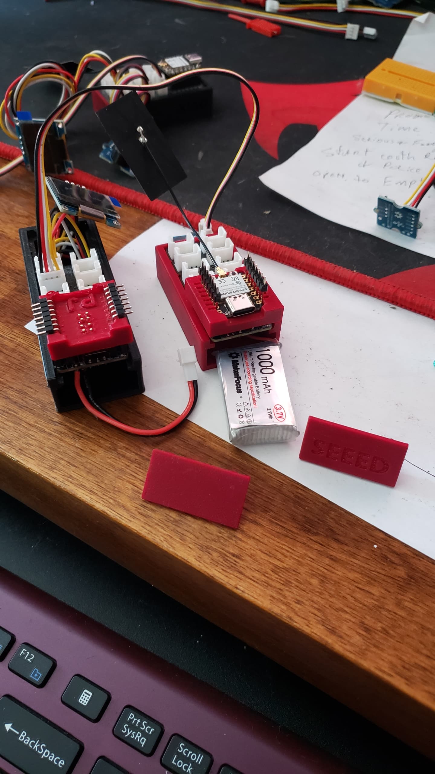
Here is a Demo of the Expansion board with the External Flash Installed and being tested. It demonstrates the Button Interrupt to SLEEP and WAKE. It’s a rough Basic demo.
The Flash is Hardwired on the board to pin (D1) and both QSPI and SPI FLash are available. extra’s is the DS18B20 and the display is a cheapy , I2C (3C),running adafruit library code.
BSP files are all 1.1.1 and LIB’s listed. I printed the case and stretched ![]()
![]() one for the bigger battery.
one for the bigger battery.
// 12/16/2023  Grove Expansion Board Flash Chip Test Code & OLED Display press button to SLEEP or Wake-UP
// from Adafruit_SPIFlash Example
// Author: PJG
//
//----------------------------------------------------------------------------------------------
// BSP : Seeed nRF52 Boards 1.1.1
// Board : Seeed XIAO nRF52840 Sense
// Grove Expansion Board & cheapest (I2C) SSD1306 display on AL-Gore Network & Grove push-button
//----------------------------------------------------------------------------------------------
// SdFat - Adafruit Fork@ 2.2.3         //    Pay close attention to the LIB versions.
// Adafruit SPIFlash@ 4.1.3             //     NOT all are compatable and New ones do NOT work
// Adafruit TinyUSB [email protected]       //   There are TOO MANY Flash libraries out. YMMV
//
// This tests and Identifies the Onboard Xiao QSPI Flash Chip
// and Expansion Flash Chip on Grove Board that is Hardwired to A1/D1 (pin 1) on Xiao
// for the Flash chipSelect CS or SS in the code
// Adafruit_SPIFlash is set with SPI class mthod. You can mix QSPI mode and SPI class are possible.
// The trick with the Nordic Nrf52x devices is the SPI interfaces as NRF_SPIM0, NRF_SPIM1, NRF_SPIM2,
// NRF_SPIM3 for which buss. device mode or method.
// HTH
//
#include <Arduino.h>
#include <SPI.h>
#include <Wire.h>
#include <SdFat.h>
#include <Adafruit_SPIFlash.h>
#include <Adafruit_GFX.h>
#include <Adafruit_SSD1306.h>
#include <LSM6DS3.h>
// Flash Chip declerations, made up from Data Sheets.
SPIFlash_Device_t const p25q16h{
  // You can Declare the chip you choose this way or add it to the flash_devices
  // Configuration for W25Q80DV flash chip from the Data Sheet.
  .total_size = (1UL << 21),  // 2MiB
  .start_up_time_us = 10000,
  .manufacturer_id = 0x85,
  .memory_type = 0x60,
  .capacity = 0x15,
  .max_clock_speed_mhz = 55,
  .quad_enable_bit_mask = 0x02,
  .has_sector_protection = 1,
  .supports_fast_read = 1,
  .supports_qspi = 1,
  .supports_qspi_writes = 1,
  .write_status_register_split = 1,
  .single_status_byte = 0,
  .is_fram = 0,
};
SPIFlash_Device_t const w25q80{
  // Also seemsto be case sensative lower case preferred
  // Configuration for W25Q80DV flash chip from the Data Sheet.
  .total_size = (1UL << 20),  // 1MiB
  .start_up_time_us = 10000,
  .manufacturer_id = 0xEF,
  .memory_type = 0x40,
  .capacity = 0x14,
  .max_clock_speed_mhz = 55,
  .quad_enable_bit_mask = 0x02,
  .has_sector_protection = 0,
  .supports_fast_read = 1,
  .supports_qspi = 1,
  .supports_qspi_writes = 0,
  .write_status_register_split = 0,
  .single_status_byte = 0,
  .is_fram = 0,
};

//Create a instance of class LSM6DS3//#define int2Pin P0_11
LSM6DS3 myIMU(I2C_MODE, 0x6A);  //I2C device address 0x6A  // IMU
#define int2Pin PIN_LSM6DS3TR_C_INT1
#define OLED_RESET -1     //2 // Reset pin # (or -1 if sharing Arduino reset pin)
#define SCREEN_WIDTH 128  // OLED display width, in pixels
#define SCREEN_HEIGHT 32  // OLED display height, in pixels
#define clkDuring 400000UL
#define clkAfter 100000UL

// Declaration for an SSD1306 display connected to I2C (SDA, SCL pins)
Adafruit_SSD1306 display(SCREEN_WIDTH, SCREEN_HEIGHT, &Wire, OLED_RESET, clkDuring, clkAfter);

const int buttonPin = 2;     // the number of the pushbutton pin
int buttonState = 0;          // variable for reading the pushbutton status
uint8_t binterruptCount = 0;  // Amount of received interrupts
const int BuzzerPin = 1;
int buzzer = BuzzerPin;
#define LEDR LED_BUILTIN  // default
#define LEDG LED_GREEN
#define LEDB LED_BLUE
//#define LED LEDB
//#define LED P0_26   // RED
//#define LED P0_30   // GREEN
//#define LED P0_6    // BLUE
uint8_t interruptCount = 0;      // Amount of received interrupts
uint8_t prevInterruptCount = 0;  // Interrupt Counter from last loop
bool first10LoopCompleted = false;

#define SS_SPI0 1  // default to Pin 7 if you don't declare it as the CS for the Flash Chip A1/D1 pin1 on the Xiao
#define SS_SPI1 25  // Defaul SS or CS for the Onboard QSPI Flash Chip

SPIClass SPI_2(NRF_SPIM0, PIN_QSPI_IO1, PIN_QSPI_SCK, PIN_QSPI_IO0);  // Onboard QSPI Flash chip
Adafruit_FlashTransport_SPI QflashTransport(PIN_QSPI_CS, SPI_2);      // CS for QSPI Flash
Adafruit_SPIFlash Qflash(&QflashTransport);

SPIClass SPI_1(NRF_SPIM3, D9, D8, D10);                       // MISO, SCK, MOSI /EXPANSION FLASH// CS pin D1 (hardwired)
Adafruit_FlashTransport_SPI EflashTransport(SS_SPI0, SPI_1);  // Flash Type
Adafruit_SPIFlash Eflash(&EflashTransport);

// ******************** START *****************//
void setup() {
  Wire.begin();
  Serial.begin(9600);
  delay(2000);
  //while (!Serial) delay(2100);      // Code will wait until USB port is plugged in.
  pinMode(BuzzerPin, OUTPUT);
  buzzer = LOW ;  // Buzzer OFF
  Serial.println();
  Serial.println("Program " __FILE__ " compiled on " __DATE__ " at " __TIME__);
  Serial.println();
  Serial.println("Processor came out of reset.");
  Serial.println();
  pinMode(D6, INPUT_PULLUP);  // /WP
  //pinMode(D7, INPUT_PULLUP);  // /HOLD
  pinMode(SS_SPI0, OUTPUT);          // CS for flash
  digitalWrite(SS_SPI0, HIGH);       // <-- Set CS pin HIGH to deselect
  pinMode(buttonPin, INPUT_PULLDOWN);  // initialize the pushbutton pin as an input: for GROVE PB
                                     //attachInterrupt(digitalPinToInterrupt(buttonPin), myISR_Falling, FALLING);
  attachInterrupt(digitalPinToInterrupt(buttonPin), myISR_Rising, RISING);
  myIMU.settings.gyroEnabled = 0;  // Gyro currently not used, disabled to save power
  myIMU.begin();
  pinMode(int2Pin, INPUT_PULLUP);
  attachInterrupt(digitalPinToInterrupt(int2Pin), int1ISR, RISING);
  setupDoubleTapInterrupt();
  startsound();  //Beep Buzzer speaker on A3
  setupblink();  // Tests The onboard RGB LED
 Serial.println("--------------");
  Serial.println(SS_SPI0);
  Serial.println(MOSI); // master out, slave in
  Serial.println(MISO); // master in, slave out
  Serial.println(SCK);  // clock
 Serial.println("--------------");
  //startDisplay();            //Serial.println("SSD1306 allocation worked");
  Serial.println("Flash Testing Now.");
  Serial.println("Onboard QSPI Flash Testing");
  Serial.println(F("QSPI Flash ID P25Q16H"));
  //flashtestDisplay();
  // Initialize QSPI flash library and check its chip ID.
  if (!Qflash.begin(&p25q16h, 1)) {
    Serial.println(F("Error, failed to initialize QSPI flash chip!"));
    while (1)
      ;
  }
  Serial.print(F("QFlash chip JEDEC ID: 0x"));
  Serial.println(Qflash.getJEDECID(), HEX);
  Serial.print(F("Flash size: "));
  Serial.print(Qflash.size() / 1024);
  Serial.println(F(" KB"));
  Serial.println(F("QFlash chip successfully ID'd!"));

  delay(1000);

  Serial.println();  // Keep Display the Same
  Serial.println("Expansion Flash testing!!");
  //digitalWrite(SS_SPI0, HIGH); // <-- Set CS pin HIGH to deselect
  Serial.println(F("SPI Flash ID W25Q80DV"));
  // Initialize W25Q80DV flash library and check its chip ID.
  if (!Eflash.begin(&w25q80,1)) {
    Serial.println(F("Error, failed to initialize W25Q80DV flash chip!"));
    while (1)
      ;
  }
  Serial.print(F("W25Q80DV chip JEDEC ID: 0x"));
  Serial.println(Eflash.getJEDECID(), HEX);
  Serial.print(F("Flash size: "));
  Serial.print(Eflash.size() / 1024);
  Serial.println(F(" KB"));
  Serial.println(F("SPI Flash chip successfully ID'd!"));
  delay(1000);
  if (!display.begin(SSD1306_SWITCHCAPVCC, 0x3C)) {  // Address 0x3C for 128x32
    Serial.println("SSD1306 allocation failed");
  }
  delay(1000);
  startDisplay();
  flashtestDisplay();
  //delay (30000);

  //sd_power_system_off();
  //NRF_POWER->SYSTEMOFF = 1;
}
// **END of SETUP **//
void loop() {
  delay(250);
  digitalWrite(LED_BUILTIN, true);
  delay(500);
  digitalWrite(LED_BUILTIN, false);
  delay(500);
  if (first10LoopCompleted == true) {
    testTheflash();
  } else
    display.clearDisplay();
  display.setTextSize(1);       // Normal 1:1 pixel scale
  display.setTextColor(WHITE);  // Draw white text
  display.setCursor(0, 0);      // Start at top-left corner
  display.display();
  //display.clearDisplay();
  //display.display();// Your code here
  buttonState = digitalRead(buttonPin);  // read the state of the pushbutton value:
  if (buttonState == HIGH) {
    display.clearDisplay();
    display.setTextSize(1);       // Normal 1:1 pixel scale
    display.setTextColor(WHITE);  // Draw white text
    display.setCursor(0, 0);      // Start at top-left corner
    display.display();            // Go do it.
    display.println("  SLEEP  ");
    display.display();
    delay(2000);
    Serial.println("SLEEP/WAKE Button Pushed");
    delay(2000);
    menuMan();
    goToPowerOff();
  } else {
    buttonState = LOW;
    //menuMan();
  }
  delay(1500);
  buttonState = digitalRead(buttonPin);  // read the state of the pushbutton value:
  display.clearDisplay();
  display.setTextSize(2);       // Normal 1:1 pixel scale
  display.setTextColor(WHITE);  // Draw white text
  display.setCursor(10, 8);     // Start at top-left corner
  display.display();            // Go do it.
  display.println("  Idle.... ");
  display.display();
  delay(1000);
  display.setTextSize(2);       // Normal 1:1 pixel scale
  display.setTextColor(BLACK);  // Draw white text
  display.setCursor(10, 8);     // Start at top-left corner
  display.display();            // Go do it.
  display.println("  Idle.... ");
  display.display();
  delay(1000);
  display.setTextSize(1);       // Normal 1:1 pixel scale
  display.setTextColor(WHITE);  // Draw white text
  display.setCursor(10, 8);     // Start at top-left corner
  //display.display();
  display.println(" POWER SAVE ");
  display.display();
  delay(500);  // Go do it.
  Serial.println("SOFT DEVICE “SYSTEM ON” POWER SAVE");
  delay(1000);
  sd_power_mode_set(NRF_POWER_MODE_LOWPWR);
  sd_power_dcdc_mode_set(NRF_POWER_DCDC_ENABLE);
  __WFE();
  __WFI();
  sd_app_evt_wait();  //SOFT DEVICE “SYSTEM ON” POWER SAVE

  delay(100);
}


//END//
void myISR_Falling() {  // Pressed Button Interrupt //
  binterruptCount++;
  buttonState = HIGH;
}
void myISR_Rising() {  // Pressed Button Interrupt //
  binterruptCount++;
  buttonState = HIGH;
}
//
// Functions *****************************************************
//
void startDisplay() {
  pinMode(LED_RED, OUTPUT);    // initialize the LED pin as an output:
  pinMode(LED_GREEN, OUTPUT);  // initialize the LED pin as an output:
  pinMode(LED_BLUE, OUTPUT);
  pinMode(LED_BUILTIN, OUTPUT);  // initialize the LED pin as an output:
  display.clearDisplay();
  display.setTextSize(1);       // Normal 1:1 pixel scale
  display.setTextColor(WHITE);  // Draw white text
  display.setCursor(0, 0);      // Start at top-left corner
  display.display();            // Go do it.
  display.println("Display (StartUp)");
  display.display();
  delay(500);
  display.clearDisplay();
  display.setCursor(0, 0);
  display.println("Power ON ");
  delay(1000);
  display.setCursor(0, 10);
  display.print("Flash Test:\n");  //Flash Test:0123456789
  display.display();
  delay(1500);
}
void flashtestDisplay() {
  display.setCursor(68, 10);
  display.print("--");
  display.display();
  delay(250);
  display.print("---");
  display.display();
  delay(250);
  display.print("---");
  display.display();
  delay(250);
  display.print("--");
  display.display();
  delay(500);
  first10LoopCompleted = true;
}
void menuMan() {
  display.setTextSize(1);       // Normal 1:1 pixel scale
  display.setTextColor(WHITE);  // Draw white text
  display.setCursor(0, 0);
  if (first10LoopCompleted = false) {
    display.println("Power ON ");
    display.display();
    delay(500);
  }
  display.setCursor(0, 10);
  display.print("Flash Test:\n");  //Flash Test:0123456789
  display.display();
  delay(100);
  display.clearDisplay();
  display.display();
  display.setCursor(12, 10);
  display.print("PASS:");
  display.print(Qflash.size() / 1024);
  display.println(F(" KB"));
  display.display();
  delay(500);
  display.setCursor(12, 18);
  display.print("PASS:");
  display.print(Eflash.size() / 1024);
  display.println(F(" KB"));
  display.display();
  delay(250);
  display.clearDisplay();
  display.display();
}
void testTheflash() {
  display.setTextColor(WHITE);  // Draw white text
  display.setTextSize(1);
  display.setCursor(4, 22);
  display.print("P25Q16H ");  // turn ON
  display.display();
  delay(500);
  display.setTextSize(2);
  display.setCursor(63, 18);
  display.print(" PASS");
  display.display();
  delay(500);
  display.setTextSize(1);
  display.setTextColor(BLACK);  // turn Off
  display.setCursor(4, 22);
  display.print("P25Q16H ");
  display.display();
  delay(500);
  display.setCursor(63, 18);
  display.setTextSize(2);
  display.print(" PASS");
  display.display();
  delay(250);
  display.setTextColor(BLACK);
  display.setCursor(63, 18);
  display.setTextSize(2);
  display.print(" PASS");
  display.display();
  delay(250);
  display.setCursor(4, 22);
  display.setTextSize(1);
  display.print("P25Q16H ");
  display.display();
  delay(500);
  display.setCursor(68, 10);
  display.setTextSize(1);
  display.print("**********");
  display.display();
  delay(500);
  display.setTextColor(WHITE);  // Draw white text
  display.setCursor(4, 22);
  display.print("W25Q80DV");
  display.display();
  delay(500);
  display.setCursor(68, 10);
  display.print("--");
  display.display();
  delay(500);
  display.print("---");
  display.display();
  delay(500);
  display.print("---");
  display.display();
  delay(500);
  display.print("--");
  display.display();
  delay(500);
  display.setCursor(63, 18);
  display.setTextSize(2);
  display.print(" PASS");
  display.display();
  delay(1000);
  display.setTextColor(BLACK);
  display.setCursor(4, 22);
  display.setTextSize(1);
  display.print("W25Q80DV");
  display.display();
  delay(500);
  first10LoopCompleted = false;
}
void setupblink() {

  setLedRGB(false, true, false);  // Red
  delay(1000);
  setLedRGB(true, false, false);  // Green
  delay(1000);
  setLedRGB(false, false, true);  // Blue
  delay(1000);
  setLedRGB(false, false, false);  // OFF
}

void setLedRGB(bool red, bool green, bool blue) {
  if (!blue) {
    digitalWrite(LEDB, HIGH);  } else {    digitalWrite(LEDB, LOW);  }
  if (!green) {
    digitalWrite(LEDG, HIGH);  } else {    digitalWrite(LEDG, LOW);  }
  if (!red) {
    digitalWrite(LEDR, HIGH);  } else {    digitalWrite(LEDR, LOW);  }
}
void startsound() {
  tone(buzzer, 890);
  delay(220);
  noTone(buzzer);
  delay(20);
  tone(buzzer, 800);
  delay(220);
  noTone(buzzer);
  delay(20);
  tone(buzzer, 800);
  delay(220);
  noTone(buzzer);
  delay(20);
  tone(buzzer, 990);
  delay(420);
  noTone(buzzer);
  delay(20);
}
void setupDoubleTapInterrupt() {

  uint8_t error = 0;
  uint8_t dataToWrite = 0;

  // Double Tap Config
  myIMU.writeRegister(LSM6DS3_ACC_GYRO_CTRL1_XL, 0x60);     //* Acc = 416Hz (High-Performance mode)// Turn on the accelerometer ODR_XL = 416 Hz, FS_XL = 2g
  myIMU.writeRegister(LSM6DS3_ACC_GYRO_TAP_CFG1, 0x8E);     // INTERRUPTS_ENABLE, SLOPE_FDS// Enable interrupts and tap detection on X, Y, Z-axis
  myIMU.writeRegister(LSM6DS3_ACC_GYRO_TAP_THS_6D, 0x03);   // was 85 Set tap threshold 8C
  myIMU.writeRegister(LSM6DS3_ACC_GYRO_INT_DUR2, 0x7F);     // Set Duration, Quiet and Shock time windows 7F
  myIMU.writeRegister(LSM6DS3_ACC_GYRO_WAKE_UP_THS, 0x80);  // Single & double-tap enabled (SINGLE_DOUBLE_TAP = 1)
  myIMU.writeRegister(LSM6DS3_ACC_GYRO_MD1_CFG, 0x08);      // Double-tap interrupt driven to INT1 pin
}

void int1ISR() {
  interruptCount++;
  ;
}

void goToPowerOff() {
  //sleepFlash();
  setLedRGB(false, false, false);
  Serial.println("Going to SLEEP System OFF  Tap to WAKE \n");
  display.clearDisplay();
  display.setCursor(10, 8);
  display.setTextSize(3);
  display.print("SLEEP");
  display.display();
  delay(500);
  display.clearDisplay();
  display.display();
  setupDoubleTapInterrupt();  // not needed here, if already applied..
  delay(2000);                // delay seems important to apply settings, before going to System OFF
  //Ensure interrupt pin from IMU is set to wake up device
  // nrf_gpio_cfg_sense_input(digitalPinToInterrupt(int2Pin), NRF_GPIO_PIN_PULLDOWN, NRF_GPIO_PIN_SENSE_HIGH);
  delay(2000);  // delay seems important to apply settings, before going to System OFF
  uint32_t pin = D2;
  pin = g_ADigitalPinMap[pin];
  nrf_gpio_cfg_sense_input(pin, NRF_GPIO_PIN_PULLDOWN, NRF_GPIO_PIN_SENSE_HIGH);
  delay(2000);  //15 seconds before turns off (if USB is plugged in, that circuit will still draw 2mA)
  Serial.println(" You're NOT doing anything, I'll Sleep.");
  delay(2000);
  sd_power_system_off();
  NRF_POWER->SYSTEMOFF = 1;
}
Compiler output
FQBN: Seeeduino:nrf52:xiaonRF52840Sense
Using board 'xiaonRF52840Sense' from platform in folder: C:\Users\Dude\AppData\Local\Arduino15\packages\Seeeduino\hardware\nrf52\1.1.1
Using core 'nRF5' from platform in folder: C:\Users\Dude\AppData\Local\Arduino15\packages\Seeeduino\hardware\nrf52\1.1.1
Zip created at C:\Users\Dude\AppData\Local\Temp\arduino\sketches\720A1DB782F83CD8F422347589643311/GroveFlash_Display_test.ino.zip
EDIT----for- - Brevity------*
Using library SPI at version 1.0 in folder: C:\Users\Dude\AppData\Local\Arduino15\packages\Seeeduino\hardware\nrf52\1.1.1\libraries\SPI
Using library Wire at version 1.0 in folder: C:\Users\Dude\AppData\Local\Arduino15\packages\Seeeduino\hardware\nrf52\1.1.1\libraries\Wire
Using library SdFat - Adafruit Fork at version 2.2.3 in folder: D:\Arduino_projects\libraries\SdFat_-_Adafruit_Fork
Using library Adafruit SPIFlash at version 4.1.3 in folder: D:\Arduino_projects\libraries\Adafruit_SPIFlash
Using library Adafruit GFX Library at version 1.11.9 in folder: D:\Arduino_projects\libraries\Adafruit_GFX_Library
Using library Adafruit BusIO at version 1.14.5 in folder: D:\Arduino_projects\libraries\Adafruit_BusIO
Using library Adafruit SSD1306 at version 2.5.9 in folder: D:\Arduino_projects\libraries\Adafruit_SSD1306
Using library Seeed Arduino LSM6DS3 at version 2.0.3 in folder: D:\Arduino_projects\libraries\Seeed_Arduino_LSM6DS3
Using library Adafruit TinyUSB Library at version 1.7.0 in folder: C:\Users\Dude\AppData\Local\Arduino15\packages\Seeeduino\hardware\nrf52\1.1.1\libraries\Adafruit_TinyUSB_Arduino
"C:\\Users\\Dude\\AppData\\Local\\Arduino15\\packages\\Seeeduino\\tools\\arm-none-eabi-gcc\\9-2019q4/bin/arm-none-eabi-size" -A "C:\\Users\\Dude\\AppData\\Local\\Temp\\arduino\\sketches\\720A1DB782F83CD8F422347589643311/GroveFlash_Display_test.ino.elf"
Sketch uses 73140 bytes (9%) of program storage space. Maximum is 811008 bytes.
Global variables use 8132 bytes (3%) of dynamic memory, leaving 229436 bytes for local variables. Maximum is 237568 bytes.
Serial port OUTPUT…
Flash Testing Now.
Onboard QSPI Flash Testing
QSPI Flash ID P25Q16H
QFlash chip JEDEC ID: 0x856015
Flash size: 2048 KB
QFlash chip successfully ID'd!

Expansion Flash testing!!
SPI Flash ID W25Q80DV
W25Q80DV chip JEDEC ID: 0xEF4014
Flash size: 1024 KB
SPI Flash chip successfully ID'd!
SOFT DEVICE “SYSTEM ON” POWER SAVE
SLEEP/WAKE Button Pushed
Going to SLEEP System OFF  Tap to WAKE

 You're NOT doing anything, I'll Sleep.
thanks to the Support staff for getting me the info I needed to help make this proof of concept and video. This external Flash makes an ESP32C3 with grove peripherie a snap with extra memory to store that important DATA ![]() The Socket, & BIG ReSeT Button Helmet are also captured in this video as well.
The Socket, & BIG ReSeT Button Helmet are also captured in this video as well.
Have fun & My special message at the end.
GL ![]() PJ
PJ ![]()
![]()