Programming LoRa-E5 with Arduino, LoRa-E5 mini Point to Point Comminucation over 24 km

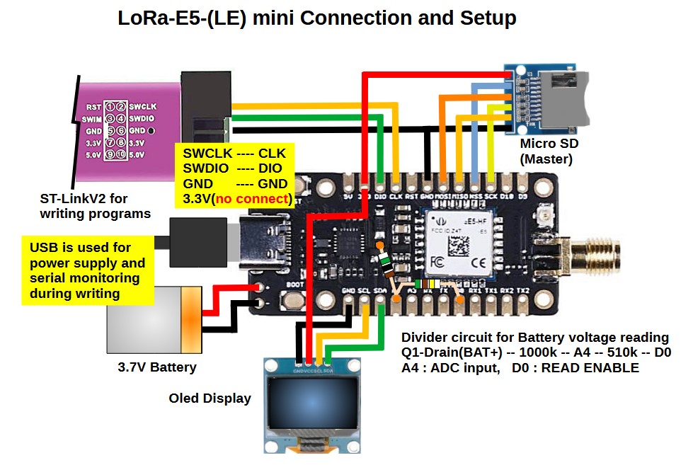
I am working on a project to program LoRa-E5 with Arduino instead of STM32CubeIDE. I hope this will be helpful to those who are interested.

As a way to program LoRa-E5 directly, the Wiki shows an example of using STM32CubeIDE. While this method is very sophisticated, it is far too complicated for me. I have found that by using some nice libraries, RadioLib, STM32LowPower, STM32RTC, I can write sketches in my familiar ArduinoIDE. I have tried and posted some basic functionality as shown in the link below.

Programming LoRa-E5 with Arduino, Grove-LoRa-E5 sleep current 0.7uA
Programming LoRa-E5 with Arduino, LoRa-E5 mini Battery Voltage Read
Programming LoRa-E5 with Arduino, Comparison of LoRa-E5 and LoRa-E5-LE transmit currents

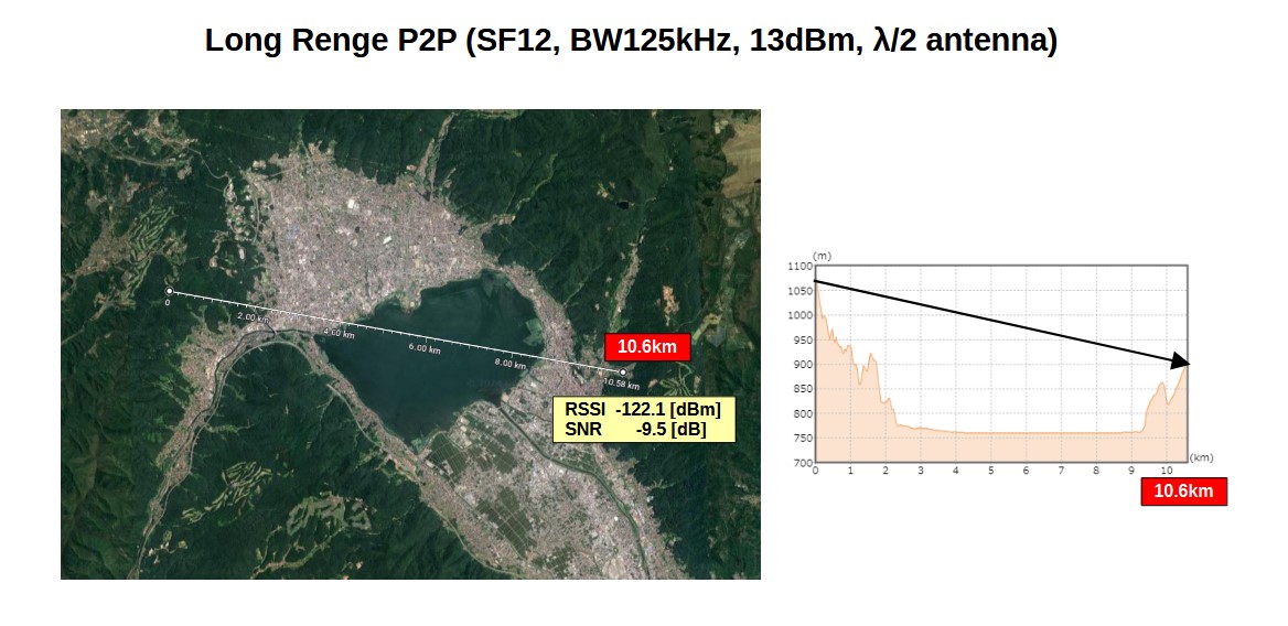
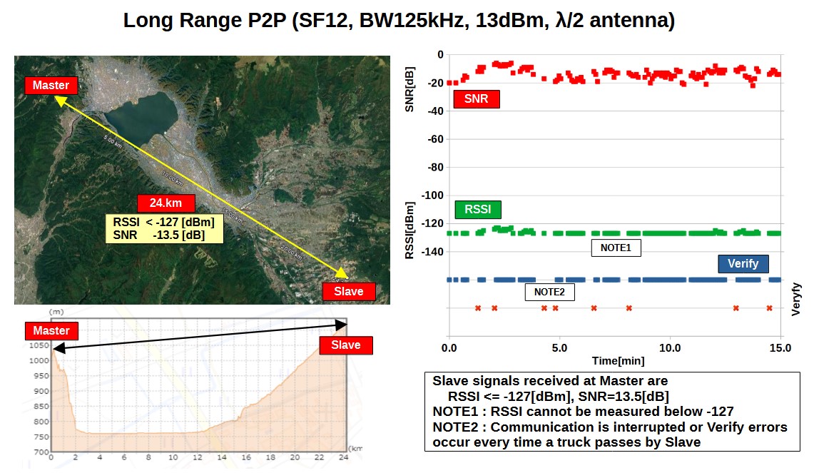
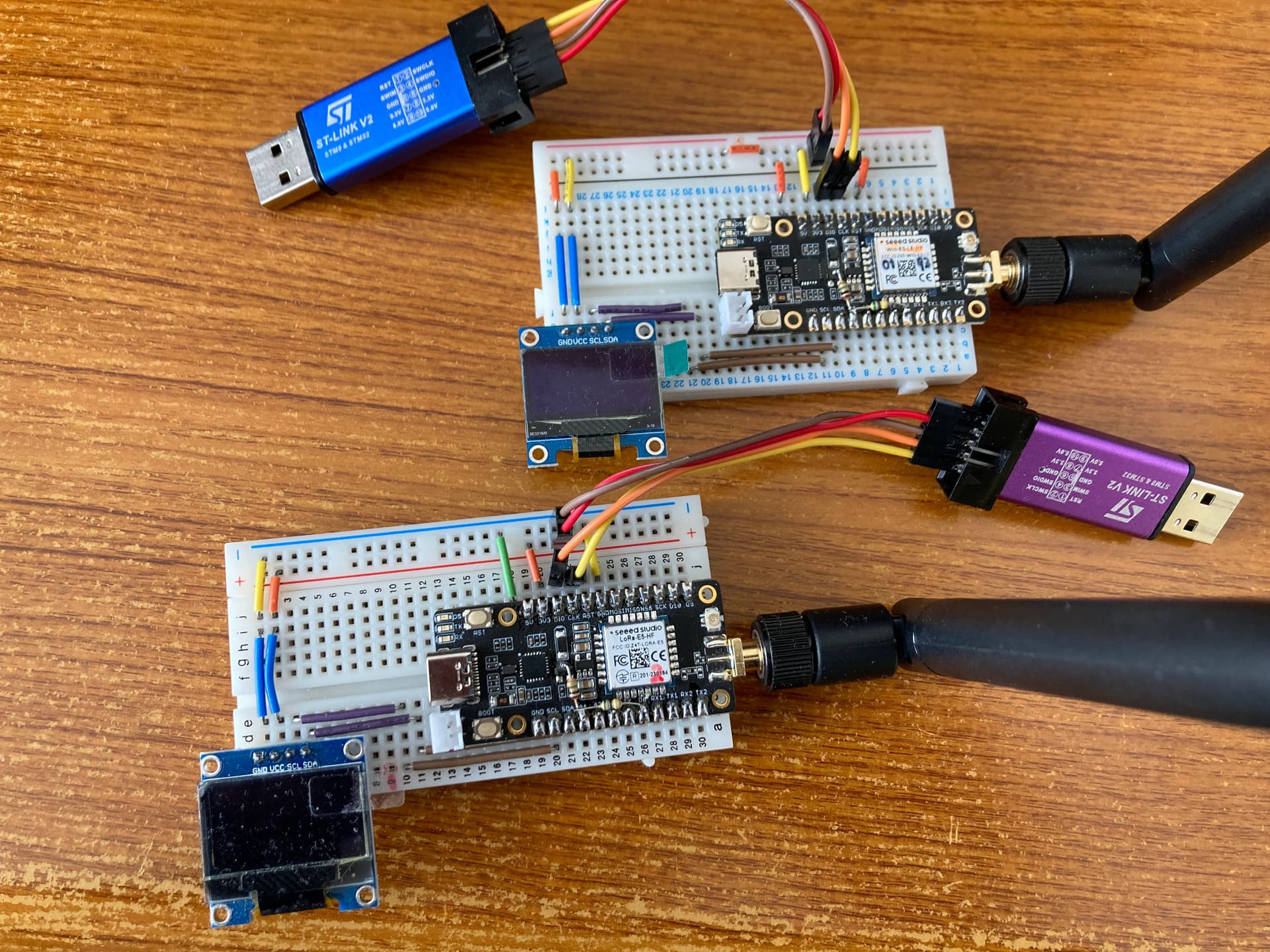
I started an experiment to investigate the possible communication distance for point-to-point communication, which was my goal. First, I made a sketch of a point-to-point communication using a LoRa-E5 mini as Master and a LoRa-E5-LE mini as Slave.
The rules for my region are: transmit power less than 20 mW, bandwidth less than 200 kHz, antenna gain less than 3 dBi, and total transmission time per hour less than 360 seconds. The main LoRa parameters I set are freq=922.6MHz, power=13dBm, bw=125kHz, sf=12, cr=5, and send a 12-byte packet.

The sequence of operation is

  1. Master waits for a packet from Slave
  2. Slave sends a 12-byte packet (Slave’s UID, transmission time, battery voltage) and waits for a response from Master.
  3. Master receives the packet, checks the Slave’s UID and sends a 12-byte packet (Master’s UID, RSSI, SNR, dummy data) in response.
  4. Slave receives the packet, checks Master’s UID, then sleeps for 10 seconds in shutdown mode and wakes up with the RTC.

The device UID is used to check if the received packet is from the intended communication partner. By including Master’s RSSI and SNR in the response packet from Master, Slave can check the strength of its own signal. The activation method is to first activate Master to put it in a receive state, then activate Slave to start communication.

This is the sketch used for the experiment.
P2P_MasterSlave.zip (34.3 KB)

**** For reference ****
When compiled with ArduinoIDE2, the hex file is created in the folder below. Select and write the file with STA32CubeProgrammer.
In case of Windows
C:\Users\username\AppData\Local\Temp\arduino\sketches\32 digit HEX string\sketchname.ino.hex
In case of Linux
/tmp/arduino/sketches/32 digit HEX string/sketchname.ino.hex

IDE :          ArduinoIDE 2.2.1
BSP :          STM32 boards groups by STMicroelectronics 2.7.1
               Borad select        STM Boards groups / LoRa boars
               Board part number   LoRa-E5 mini (from Tools submenu 'Board part number')
Programmer :   STM32CubeProgrammer
Uploader :     ST-Link V2
Library :      RadioLib 6.4.2      https://github.com/jgromes/RadioLib
               STM32LowPower 1.2.5 https://github.com/stm32duino/STM32LowPower
               STM32RTC 1.4.0      https://github.com/stm32duino/STM32RTC

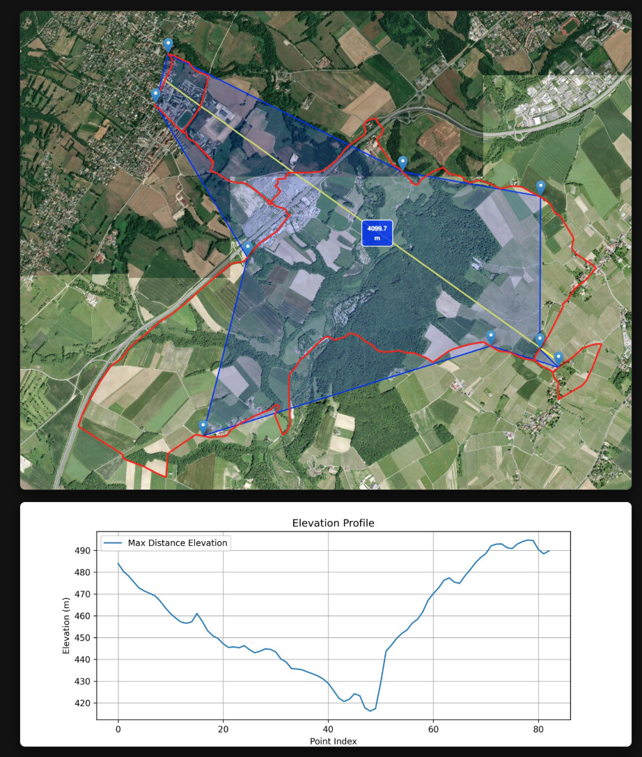
So far, results of 3.5 km have been obtained, and further experiments are planned.
I hope this will be helpful to those who are interested.

3 Likes

Wow, That is “BALLING” 3.5 Km, I love the technique , self SSI check pretty great stuff Msfujino
I would expect nothing less. My units are on order :wink: :v:
So the LE is very good on low power then?
Awesome stuff my guy.
GL :slight_smile: PJ

LoRa-E5 is an old design; it would be nice to have a LoRa version of XIAO, XIAO_LoRa_LE, similar to XIAO_BLE.

1 Like

Hi there,
Yes, they should be able too , make it just like that GnSS (GPS) Xiao.
But I want a 3G/4G Xiao. That would be the Winner too.
GL :slight_smile: PJ

In my area, the maximum possible experimental sight distance is 10 km, so I tried 10 km point-to-point communication. I chose a straight line over a lake, avoiding over urban areas as much as possible.
The result was a distance of 10.6 km, RSSI of -122.1 dBm, and SNR of -9.5 dB, ensuring stable communication. Since the theoretical limit of RSSI is -136.5 dBm, there is still a possibility to extend the distance.

Sketches used in the experiment
ESP32WL_P2P_LongRange.zip (30.3 KB)

3 Likes

Hello,
I am looking for LORA-E5 module software(source code) that enables it for LORA point-point communication. Please let me know if you can help me with this.

Thank you,
Naga.

look at the top of this thread he list several arduino libs he used with arduino IDE

In my previous experiments I had been able to achieve a communication distance of 10 km.
To further extend the communication distance, I used Google Map to find a line-of-sight route. The result was communication over a distance of 24.5 km, RSSI below the measurement limit of -127[dBm], and SNR of -15[dB]. However, it was susceptible to noise, and every time a truck passed by Slave, communication was lost or a verify error occurred, so I think 24 km is the limit.

The procedure is,

  1. Slave sends a packet (slave ID, random numbers, battery voltage, previous verify result) and waits for the response from Master
  2. Master receives a packet, checks the slave ID, and sends a packet (master ID, received random numbers, RSSI, SNR, time) in response. Record data to SD.
  3. Slave receives a packet, checks the master ID, and compares the received random numbers with the sent random numbers.

Sketches used in the experiment
STM32WL_P2P_Verify.zip (31.0 KB)

edit:
There was a problem with some of the sketches.
Since there are many devices communicating in the city, we may always need to check the ID of the communication partner. Here is the corrected sketch.
STM32WL_P2P_Verify_1.zip (31.1 KB)

3 Likes

Hello. Achieving 24.5 km was quite interesting in my part. What antenna did you use? And what is its gain?

As you can see in the photo in POST#1, it is a 1/2 wavelength antenna that comes with the LoRa-E5 mini. The gain is probably 3 dBi.

Very cool project!! Any of you have been able in the same project (or any) using LoRa-E5-Mini along with ArduinoIDE to use another UART than the #1 (used with USB serial link)? I’ve tried to initiate UART2 as well as LPUART, no success at all!

Hi there,

and Welcome here…

I would ask you post the code using the code tags above “</>” just paste it in there.
makes reading it and replying WAY easier, and you get better quality help. :+1:

You’ll need a few more posts before you can put up Pic’s etc.Just reply on here and ask any questions you may have, I don’t see why it wouldn’t be possible to use the other uart unless the pins are NOT available, then remapping to others is possible but requires some nuance in the Setup for the code to work.

HTH
GL :slight_smile: PJ :v:

Read @msfujino threads on it and other topics , you can get up to speed very quick that way! :wink:

Using Wio-SX1262 for XIAO instead of LoRa-E5 mini, I confirmed that point-to-point communication over 24.5 km is possible. I have posted the link below. Since the same SX1262 is installed, I think the communication performance is the same.

1 Like

Hi, i just set this up on two wio-e5-le mini boards i have at home and can confirm it is working! I’ll be going out tomorrow and seeing what distance i can achieve! Thanks for your upload and clear code!

Hi Furrah,

Please let us know when you get the results.

Today I was only able to achieve 2km… However, the master was sitting in a window in the house and i live in an old french farmhouse… I also don’t really believe the RSSI values im seeing. I noticed in your code you were running the transmitter at low power. PA4 PA5 both high. Did you get better results at high power, low, high?

Also, have you ever tried to work with stm32Cube using the HAL libraries for lora communication?

The settings for PA4 and PA5 differ depending on the type of Wio-E5 mini you are using.
For Wio-E5-LE-HF, it is {HIGH, HIGH}; for Wio-E5-HF, it is {LOW, HIGH}. Please be careful not to confuse these settings. Also, RSSI degrades rapidly if the other device is not in line of sight.

I have never used stm32Cube because its usage is complex.

can you point me to the documentation that says this? “For Wio-E5-LE-HF, it is {HIGH, HIGH}; for Wio-E5-HF, it is {LOW, HIGH}.”

on the website ( Wio-E5 mini | Seeed Studio Wiki ) for the Wio-E5-LE mini it says this.

Wio-E5 module ONLY transmits through RFO_HP:

  • Receive: PA4=1, PA5=0

  • Transmit(high output power, SMPS mode): PA4=0, PA5=1

As you say this is for the E5 module but i cant find information for the LE.

https://www.st.com/resource/en/application_note/an5457-rf-matching-network-design-guide-for-stm32wl-series-stmicroelectronics.pdf

See ”Figure 17. Example of matching networks needed when the two RF outputs are used as a bias switch”.
This provides a reference for the concept. PA4 and PA5 are used as control inputs to switch between LP and HP via the RF switch.

1 Like

Thank you for the information. I thought i’d also give you an update of a test ran today. I managed 4km with this setup int st = radio.begin(868.1, 125.0, 12, 8, 0x12, 14, 12, 1.7, 0);

I dont think ill be able to achieve further as this is between two valleys where I live. The yellow line is the max distance point to point and the plot below is the elevation between those two points. As i went over the crest of the hill it didnt take long before the signal was lost. The red line is the bike ride route i took. The markers are where i measured good transmission of data.

2 Likes