Using the “Wio-SX1262 for XIAO” to easily build LoRa point-to-point communication with various XIAOs

“Wio-SX1262 for XIAO” can be easily connected to a variety of XIAOs,
LoRa point-to-point communication can be built using Arduino. And using the RadioLib library for LoRa, sketch will work on any XIAO without modification. I tried the following XIAOs SAMD21, nRF52840, RP2040, ESP32C3, ESP32S3, ESP32C6, MG24, but nRF52840(mbed) and MG24 could not be compiled because they are not supported by RadioLib.
As shown in the link below, “LoRa-E5 mini” with SX1262 has a communication range of over 24 km, so I expect the same performance from “Wio-SX1262 for XIAO”.

The sketch used in the experiment is here.
SX1262_XIAOs_P2P.zip (4.5 KB)

1 Like

HI there,

NICE! work my guy :+1: I get the mbed is going away anyway , but the MG24 again misses the boat… Not worthy of the Xiao badge IMO.

I would have a talk with the product manager who brought it in :bomb:

I’ll be setting this up with the New S3 set they are selling. still waiting on the DHL… so more to come. How HIGH from the ground was the far end receiver please? was angle UP or down?

GL :slight_smile: PJ :v:

The mountain slope where I did the experiment last year is still off limits due to snow, so I have not done the communication experiment. I will try to measure the communication distance next month.
My “Wio-SX1262 for XIAO” has only D0, D6, and D7 IO pins left when connected to XIAO, so I had a little trouble connecting the I2C display.

1 Like

If you update RadioLib library to 7.1.2, it will also compile with MG24.

Hi there,

I’ll give it a go the set just arrived… :+1:


GL :slight_smile: PJ :v:

I recently bought the Wio-SX1262 for XIAO for my XIAO ESP32S3, however I have been getting poor results in terms of range. I am not sure why this is happening and would love some suggestions. With +22 dBm transmit power, the Wio should have no problem with several kilometer link distances, but it comes nowhere near this in reality. Compared to my RFM95 LoRa transcievers, which are only capable of +20 dBm versus the Wio SX1262’s +22 dBm, I get only a tiny fraction of the range for line-of-sight even though the Wio has greater transmit power. I saw some posts suggesting issues with the IPEX connector, so tried soldering some 50-ohm coax directly to the ANT and GND pins of the Wio SX1262 module, but this made the performance even worse with an RSSI decrease of tens of decibels. I am using identical settings to the OP of this post, so it’s not a software issue that’s causing this poor range. Any suggestions?

A little off-topic but still interesting: the schematic for the Wio SX1262 module indicates that the impedance at the ANT pin is 50 ohms. Since the IPEX connector and coaxial cable are 50 ohms as well, no matching network should be necessary between ANT and the IPEX connector. Despite this, there is definitely something in between ANT and the IPEX connector because I get zero continuity between ANT and the center pin of the IPEX connector. I wonder what they’ve added here and why? Are there updated/more detailed schematics available for the Wio-SX1262 module?

Hi CRUSTY,
I have not yet measured the detailed communication distance, just experimented in my house.

What antennas are used for Tx and Rx?
What is the critical communication distance?
Also, what is the RSSI value at that time?

I have the wio-SX1262 linked below which does not have the 30-pin connector implemented. If you read the post and replies in the last part of the wiki, there is a link to the drawing.

The SX1262 datasheet is available here
“14.6.2 Application Design of the SX1262 with RF Switch” would be helpful.

[EDIT]
I haven’t looked into this in detail yet, but perhaps the RF_SW pin needs to be controlled by XIAO.
[EDIT]
To put the RF switch in receive mode, add the following to the receive side sketch.

#define RF_SW D5           // RF_SW HIGH:Rx, LOW:default

pinMode(RF_SW, OUTPUT);    // RF_SW
digitalWrite(RF_SW, HIGH); // Receive mode

The sketch has been modified due to missing control of the RF_SW pin.
SX1262_XIAOs_P2P_RFSW.zip (4.7 KB)

According to the Meshtastic source code, the B2B connector pin for the 30-pin connector that corresponds to RF_SW is pin 38. I also noticed that the Wio-SX1262 introduction shows the RF switch as having two control connections, one to RF_SW and the other to DIO2:

To get the proper behavior from DIO2, I called radio.setDio2AsRfSwitch(true);. Doing this in addition to setting RF_SW to LOW during transmit appears to have greatly improved my RSSI. At a range of 4 feet, the RSSI went from -50 dBm to -10 dBm. My tests are using 915 MHz “rubber ducky” helical antennas which have gotten several km range using other transmitter modules.

So in summary: set RF_SW (B2B pin 38) to HIGH during receive and LOW during transmit, as @msfujino pointed out, but also make sure you call radio.setDio2AsRfSwitch(true) right after initializing the radio. It is unclear what the default behavior for DIO2 is in this module, so it may not be necessary to call radio.setDio2AsRfSwitch(true), however without knowing the default behavior you should call it either way.

By the way @msfujino, I noticed that in both your TX and RX programs, you set RF_SW to HIGH, when it should instead be HIGH for receive only and LOW for transmit only. I figure it was a simple mistake but just wanted to point it out.

See the following link: Table 5. Single-pin Control Logic Truth Table

I am currently preparing for a long-distance communication experiment.

Hi there,

Good stuff forsure, I’m looking at the set I have was getting bad data in the receive, but good transmit maybe this is what’s missing on it.
Here’s the Pins and the Truth tables


HTH
GL :slight_smile: PJ :v:

1 Like

My apologies if I’m missing something here, but this table from the Wio-SX1262 introduction seems to suggest that RF_SW on the Wio module should be logic high when receiving but logic low at all other times (row 1):

If the RF switch is connected with pin 6 to DIO2 and pin 4 to RF_SW, then Table 6 would be correct as DIO2 is logic 1 for TX. But that’s assuming RF1 is connected to the receive path, which I’m not sure of. And if the single-pin configuration is being used, then I guess I shouldn’t be calling radio.setDio2AsRfSwitch(). I dunno, I’m far too tired to make sense of this. Also more info from Seeed would be useful here, or a good de-lidded photo of the Wio-SX1262 module to settle how the RF switch is connected.

LOW1 describes “Complementary-pin Control Logic”.
RF_SW is fixed to HIGH, it becomes “Single-pin Control Logic”.
Either method may be used.
Regardless of the state of the external pin RF_SW, the SX1262 is probably just switching Rx/Tx with DIO2.

Hi there,

So, I’ll add this…


Shows what’s NOT connected … LOL :+1:

HTH

GL :slight_smile: PJ :v:

For display, I was a bit surprised that some code I work with required no updates for this OLED and the Xiao expansion base… I was doubting pins where available, but it worked with the default code… one miracle in a string of pain getting the pin mapping for the rest of the setup!

I realize after looking harder, you used the newer Xiao SX1262 base rather than the meshtastic kit with the smaller sx1262 board… So that probably explains the difference.
Can it plug in to the expansion base?

1 Like

This is the Wio-SX1262 I am using.
I can’t use the XIAO expansion board because most of the XIAO pins are used to connect to the SX1262.

Hi there,

So it took awhile to get it sorted out, but I got the Ping Pong going with some AI help.

The “HomeBase” unit sends a PING packet every 30 seconds and the “Rover” responds with a PONG packet and so On…

BSP 3.1.3 was used along with RadioLib 7.1.2 RAW dog , just the bare units.

// REV 4.0 - HomeBase_RadioLib_SX1262_v4.42c
// SX1262 Ping Sender (HomeBase Unit)
// Sends PING with UID and millis timestamp every 5 seconds
// LED lights up on TX (GPIO 48) and blinks if valid PONG is received
// Uses RadioLib v7.1.2 with blocking transmit/receive

#include <RadioLib.h>

const uint32_t TX_UID = 0x1234ABCDUL;
#define TX_INTERVAL   5000 // adjust the time here
#define LED_GPIO      48

SX1262 radio = new Module(41, 39, 42, 40); // NSS, DIO1, RST, BUSY
uint8_t txBuffer[12];
uint8_t rxBuffer[12];
unsigned long lastTxTime = 0;

void setup() {
  Serial.begin(115200);
  delay(300);
  Serial.println();
  Serial.println(F("// REV 4.0 - HomeBase_RadioLib_SX1262_v4.42c"));
  Serial.println(F("// SX1262 Ping Sender (HomeBase Unit)"));
  Serial.println(F("// LED lights up on TX (GPIO 48)"));

  pinMode(LED_GPIO, OUTPUT);
  digitalWrite(LED_GPIO, LOW);

  Serial.print(F("Initializing Radio... "));
  int state = radio.begin();
  if (state == RADIOLIB_ERR_NONE) {
    Serial.println(F("Radio initialized successfully!"));
  } else {
    Serial.print(F("Radio init failed! Code: "));
    Serial.println(state);
    while (true);
  }

  Serial.println(F("HomeBase Ready. Sending Pings..."));
}

void loop() {
  if (millis() - lastTxTime >= TX_INTERVAL) {
    lastTxTime = millis();

    memcpy(&txBuffer[0], &TX_UID, 4);
    memcpy(&txBuffer[4], &lastTxTime, 4);
    memcpy(&txBuffer[8], "PING", 4);

    Serial.print(F("HomeBase Transmitting: "));
    for (int i = 0; i < 12; i++) {
      Serial.print(txBuffer[i], HEX); Serial.print(" ");
    }
    Serial.println();

    digitalWrite(LED_GPIO, HIGH);
    int state = radio.transmit(txBuffer, 12);
    digitalWrite(LED_GPIO, LOW);

    if (state == RADIOLIB_ERR_NONE) {
      Serial.println(F("Ping Sent Successfully!"));
    } else {
      Serial.print(F("Transmission Failed! Code: "));
      Serial.println(state);
    }

    state = radio.receive(rxBuffer, 12);
    if (state == RADIOLIB_ERR_NONE) {
      Serial.print(F("PONG received! Data: "));
      for (int i = 0; i < 12; i++) {
        Serial.print(rxBuffer[i], HEX); Serial.print(" ");
      }
      Serial.println();

      uint32_t receivedUID;
      memcpy(&receivedUID, &rxBuffer[0], 4);
      if (receivedUID == TX_UID) {
        Serial.println(F("PONG UID match confirmed."));
        digitalWrite(LED_GPIO, HIGH);
        delay(100);
        digitalWrite(LED_GPIO, LOW);
      } else {
        Serial.print(F("PONG UID mismatch! Received: 0x"));
        Serial.println(receivedUID, HEX);
      }
    } else {
      Serial.println(F("No response received."));
    }
  }
}

Serial output… HomeBase

22:35:54.485 -> 
22:35:54.485 -> // REV 4.0 - HomeBase_RadioLib_SX1262_v4.42c
22:35:54.485 -> // SX1262 Ping Sender (HomeBase Unit)
22:35:54.485 -> // LED lights up on TX (GPIO 48)
22:35:54.485 -> Initializing Radio... Radio initialized successfully!
22:35:54.485 -> HomeBase Ready. Sending Pings...
22:35:58.479 -> HomeBase Transmitting: CD AB 34 12 88 13 0 0 50 49 4E 47 
22:35:58.700 -> Ping Sent Successfully!
22:35:59.113 -> No response received.
22:36:03.497 -> HomeBase Transmitting: CD AB 34 12 10 27 0 0 50 49 4E 47 
22:36:03.681 -> Ping Sent Successfully!
22:36:03.867 -> PONG received! Data: CD AB 34 12 FA 10 0 0 50 4F 4E 47 
22:36:03.867 -> PONG UID match confirmed.
22:36:08.513 -> HomeBase Transmitting: CD AB 34 12 98 3A 0 0 50 49 4E 47 
22:36:08.699 -> Ping Sent Successfully!
22:36:08.868 -> PONG received! Data: CD AB 34 12 82 24 0 0 50 4F 4E 47 
22:36:08.868 -> PONG UID match confirmed.
22:36:13.495 -> HomeBase Transmitting: CD AB 34 12 20 4E 0 0 50 49 4E 47 
22:36:13.679 -> Ping Sent Successfully!
22:36:13.864 -> PONG received! Data: CD AB 34 12 A 38 0 0 50 4F 4E 47 
22:36:13.864 -> PONG UID match confirmed.
22:36:18.501 -> HomeBase Transmitting: CD AB 34 12 A8 61 0 0 50 49 4E 47 
22:36:18.687 -> Ping Sent Successfully!
22:36:18.858 -> PONG received! Data: CD AB 34 12 92 4B 0 0 50 4F 4E 47 
22:36:18.858 -> PONG UID match confirmed.

Rover Code

// REV 4.0 - Rover_RadioLib_SX1262_v4.42c
// SX1262 Ping Receiver (Rover Unit)
// Listens for PING with matching UID and sends back PONG
// LED lights up on RX and TX (GPIO 48)
// Uses RadioLib v7.1.2 with blocking receive/transmit

#include <RadioLib.h>

const uint32_t TX_UID = 0x1234ABCDUL;
#define LED_GPIO      48

SX1262 radio = new Module(41, 39, 42, 40); // NSS, DIO1, RST, BUSY
uint8_t rxBuffer[12];
uint8_t pongData[12];
unsigned long lastTimeoutPrint = 0;

void setup() {
  Serial.begin(115200);
  delay(300);
  Serial.println();
  Serial.println(F("// REV 4.0 - Rover_RadioLib_SX1262_v4.42c"));
  Serial.println(F("// SX1262 Ping Receiver (Rover Unit)"));
  Serial.println(F("// LED lights up on RX/TX (GPIO 48)"));

  pinMode(LED_GPIO, OUTPUT);
  digitalWrite(LED_GPIO, LOW);

  Serial.print(F("Initializing Radio... "));
  int state = radio.begin();
  if (state == RADIOLIB_ERR_NONE) {
    Serial.println(F("Radio initialized successfully!"));
  } else {
    Serial.print(F("Radio init failed! Code: "));
    Serial.println(state);
    while (true);
  }

  Serial.println(F("Rover Ready. Listening for Pings..."));
}

void loop() {
  int state = radio.receive(rxBuffer, 12);
  if (state == RADIOLIB_ERR_NONE) {
    Serial.print(F("Packet received successfully! Data: "));
    for (int i = 0; i < 12; i++) {
      Serial.print(rxBuffer[i], HEX); Serial.print(" ");
    }
    Serial.println();

    uint32_t receivedUID;
    memcpy(&receivedUID, &rxBuffer[0], 4);
    Serial.print(F("Extracted UID: 0x")); Serial.println(receivedUID, HEX);

    if (receivedUID == TX_UID) {
      Serial.println(F("PING received and TX_UID match!"));
      digitalWrite(LED_GPIO, HIGH);

      memcpy(&pongData[0], &TX_UID, 4);
      unsigned long now = millis();
      memcpy(&pongData[4], &now, 4);
      memcpy(&pongData[8], "PONG", 4);

      Serial.println(F("Sending PONG..."));
      int txState = radio.transmit(pongData, 12);
      if (txState == RADIOLIB_ERR_NONE) {
        Serial.println(F("PONG sent successfully!"));
      } else {
        Serial.print(F("PONG send failed! Code: "));
        Serial.println(txState);
      }
      digitalWrite(LED_GPIO, LOW);
    }
  } else {
    if (millis() - lastTimeoutPrint > 5000) {
      Serial.println(F("Reception Timeout..."));
      lastTimeoutPrint = millis();
    }
  }
}

Rover serial Output.

22:36:00.023 -> 
22:36:00.023 -> // REV 4.0 - Rover_RadioLib_SX1262_v4.42c
22:36:00.023 -> // SX1262 Ping Receiver (Rover Unit)
22:36:00.023 -> // LED lights up on RX/TX (GPIO 48)
22:36:00.023 -> Initializing Radio... Radio initialized successfully!
22:36:00.023 -> Rover Ready. Listening for Pings...
22:36:03.681 -> Packet received successfully! Data: CD AB 34 12 10 27 0 0 50 49 4E 47 
22:36:03.681 -> Extracted UID: 0x1234ABCD
22:36:03.681 -> PING received and TX_UID match!
22:36:03.681 -> Sending PONG...
22:36:03.867 -> PONG sent successfully!
22:36:04.689 -> Reception Timeout...
22:36:08.698 -> Packet received successfully! Data: CD AB 34 12 98 3A 0 0 50 49 4E 47 
22:36:08.698 -> Extracted UID: 0x1234ABCD
22:36:08.698 -> PING received and TX_UID match!
22:36:08.698 -> Sending PONG...
22:36:08.835 -> PONG sent successfully!
22:36:10.120 -> Reception Timeout...
22:36:13.679 -> Packet received successfully! Data: CD AB 34 12 20 4E 0 0 50 49 4E 47 
22:36:13.679 -> Extracted UID: 0x1234ABCD
22:36:13.679 -> PING received and TX_UID match!
22:36:13.679 -> Sending PONG...
22:36:13.864 -> PONG sent successfully!
22:36:15.530 -> Reception Timeout...
22:36:18.687 -> Packet received successfully! Data: CD AB 34 12 A8 61 0 0 50 49 4E 47 
22:36:18.687 -> Extracted UID: 0x1234ABCD
22:36:18.687 -> PING received and TX_UID match!
22:36:18.687 -> Sending PONG...
22:36:18.858 -> PONG sent successfully!

With the time stamps you can see a couple good observations.
for one sub -200ms. round-trip time. and I have delays in there, and I am polling the receiver mode. 5 second Stable cycle. (drop the number to 500 from 5000 in HomeBase)
#define TX_INTERVAL 5000 // adjust the time here for a more continuous Volly

HTH
GL :slight_smile: PJ :v:

1 Like

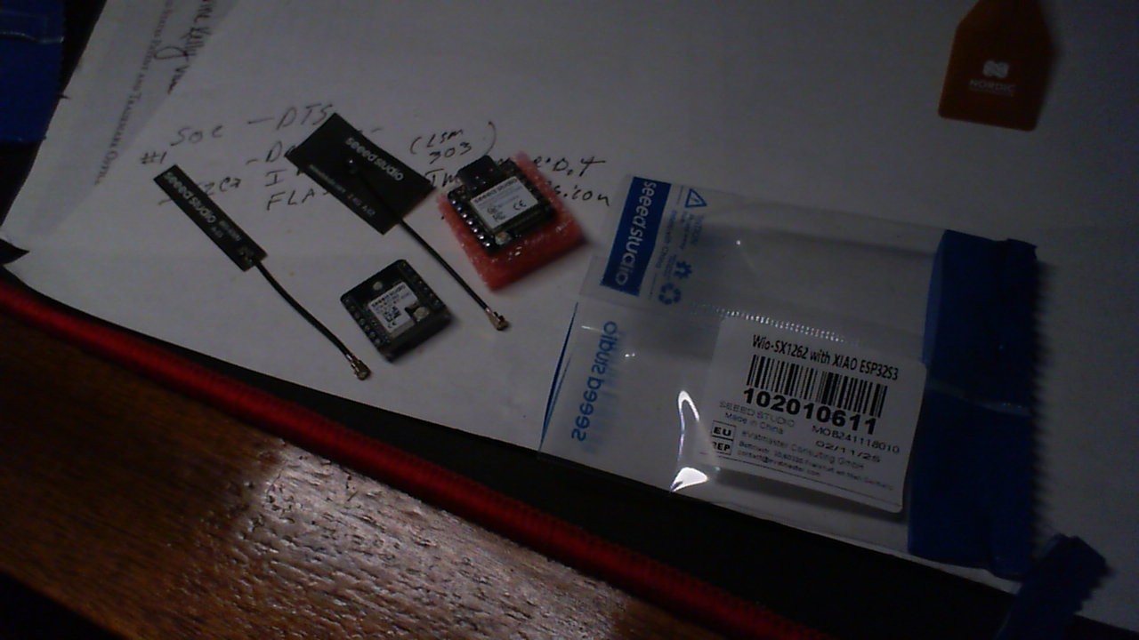
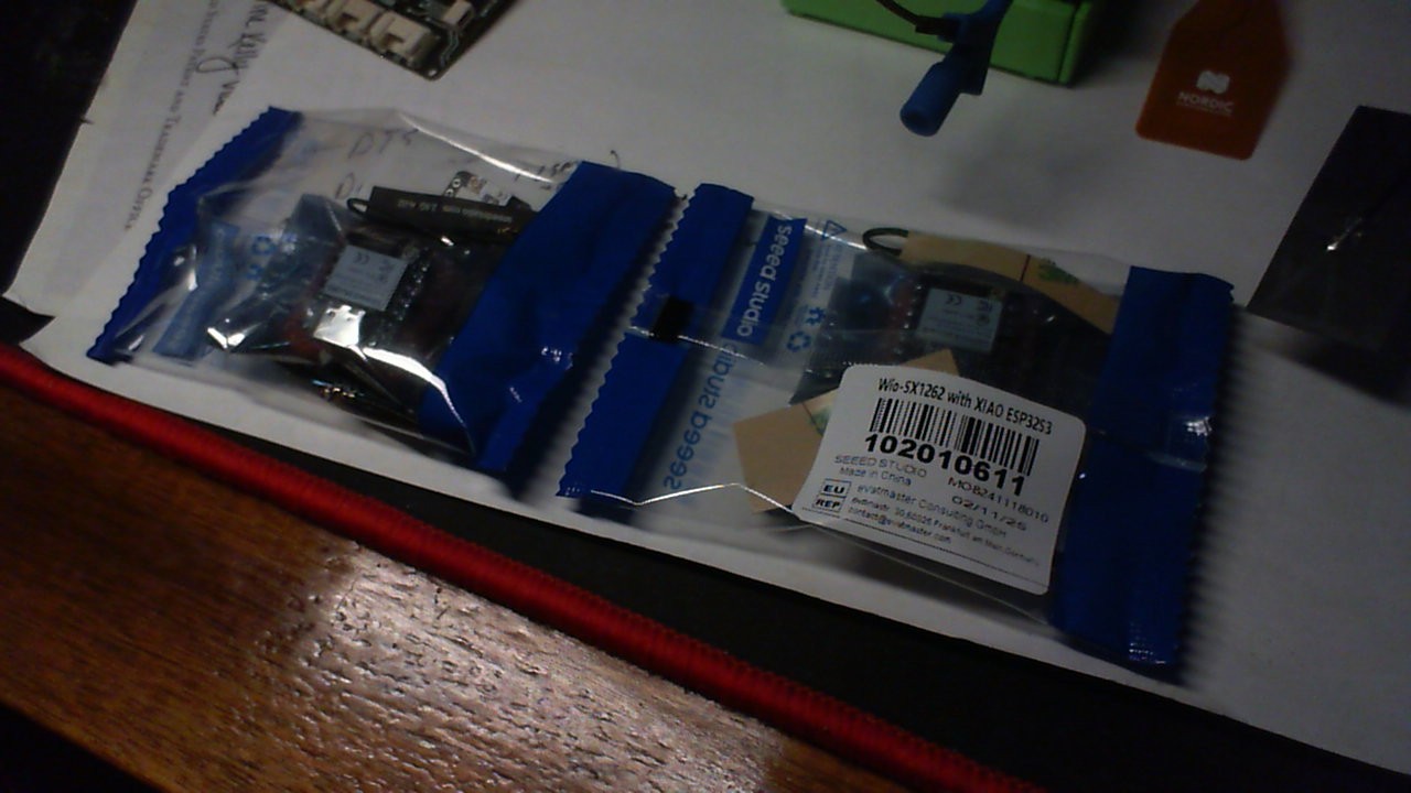
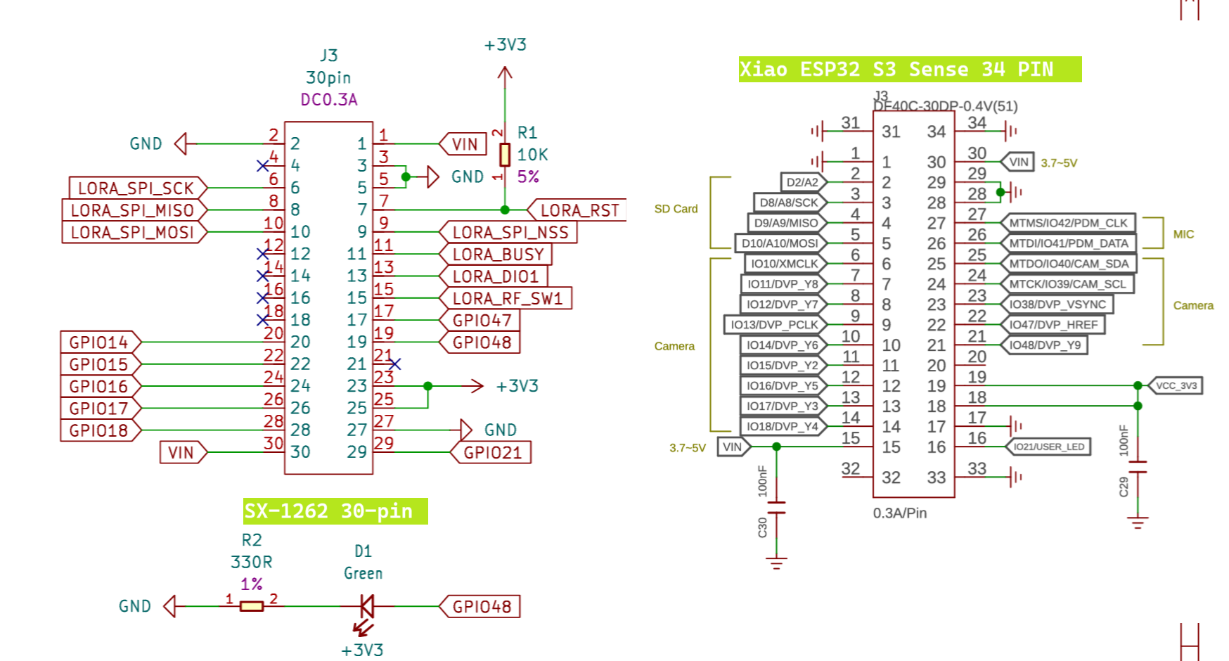
WIO SX-1262 & Xiao ESP32S3 Kit (test demo)

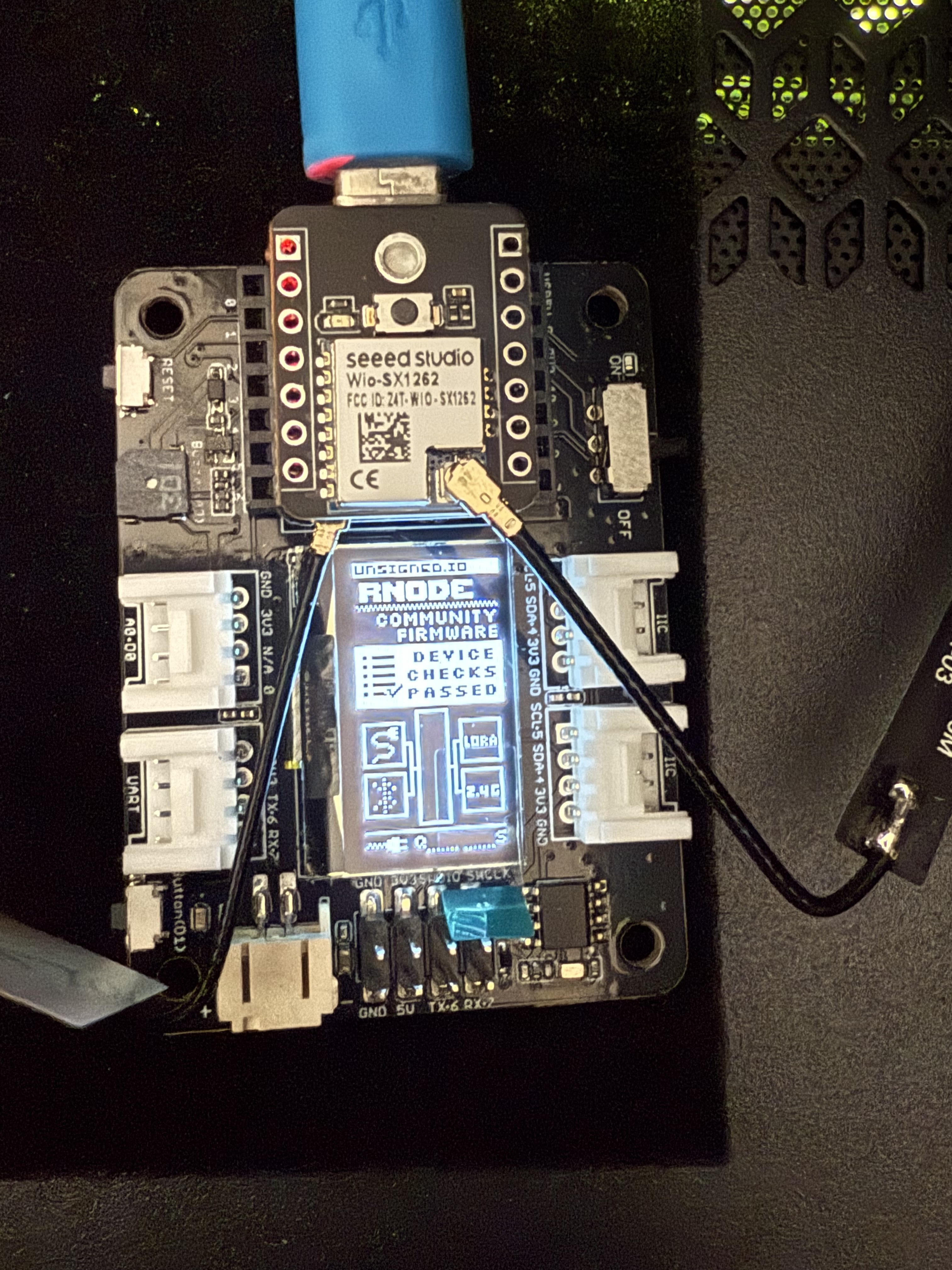
Here is a test code snip to check your Hardware and get the basics Handled, Runs a test on the parts, Blinks the LED , checks the PushButton and after it passes becomes a LORA beacon , The other Part is an OPEN LORA Receiver.
Same rules apply as above…
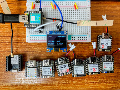
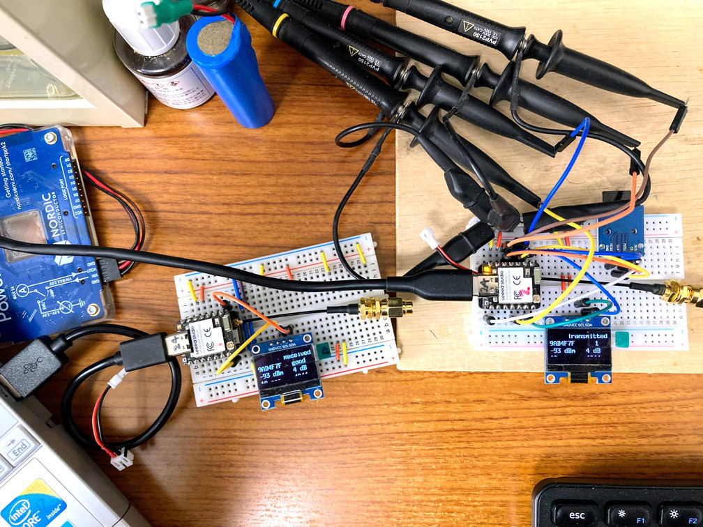
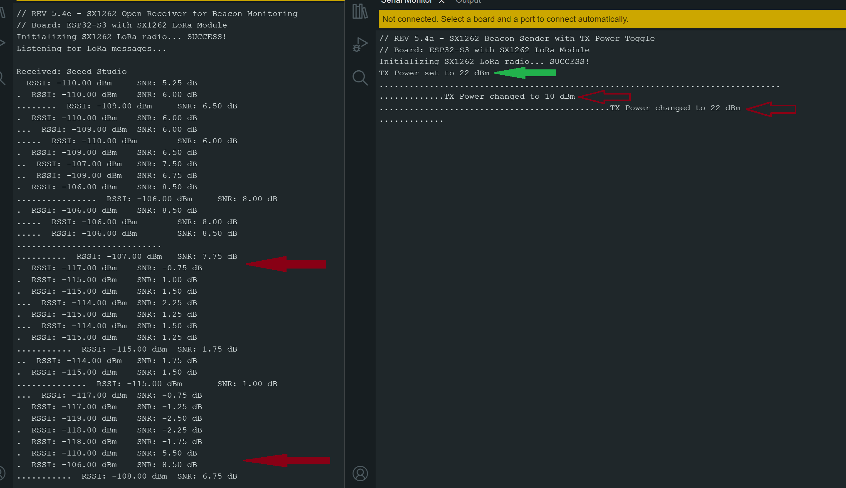
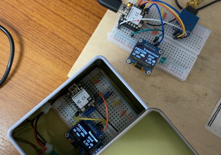
Returns RSSI and SNR of beacon and if you press the Button on the transmitter it will change the power level of the beacon. Here are some screen shots of the two units about 18 inches to 2’ apart.
It prints the values(updates) if they change more than .25 dB or .25 dBm the period mean it still matched but RSSI & SNR are the same. You can send any Beacon message and the first one will be passed the rest if matched will be a DOT (.)


Red Arrows are when I pressed the button(power level change)

Sx1262 _Diags & Beacon_Sender;

// REV 5.4a - SX1262 Beacon Sender with TX Power Toggle
// Board: ESP32-S3 with SX1262 LoRa Module
// Sends "Seeed Studio" beacon every 3 seconds
// Button on GPIO 21 toggles power (10 <-> 22 dBm)
// LED on GPIO 48 blinks on each send

#include <RadioLib.h>

SX1262 radio = new Module(41, 39, 42, 40);  // NSS, DIO1, RST, BUSY

const char* message = "Seeed Studio"; // just change this to whatever...Beacon message you want //
const int ledPin = 48;
const int buttonPin = 21;

int currentPower = 22;
bool lastButton = HIGH;

void setup() {
  Serial.begin(115200);
  delay(1000);

  pinMode(ledPin, OUTPUT);
  pinMode(buttonPin, INPUT_PULLUP);

  Serial.println(F("// REV 5.4a - SX1262 Beacon Sender with TX Power Toggle"));
  Serial.println(F("// Board: ESP32-S3 with SX1262 LoRa Module"));
  Serial.print("Initializing SX1262 LoRa radio... ");
  if (radio.begin() != RADIOLIB_ERR_NONE) {
    Serial.println("FAILED!");
    while (true);
  }
  Serial.println("SUCCESS!");

  // Apply standard LoRa settings
  radio.setSpreadingFactor(7);
  radio.setBandwidth(125.0);  // ✅ correct for newer versions
  radio.setCodingRate(5);
  radio.setOutputPower(currentPower);
  Serial.print("TX Power set to ");
  Serial.print(currentPower);
  Serial.println(" dBm");
}

void loop() {
  bool button = digitalRead(buttonPin);
  if (button == LOW && lastButton == HIGH) {
    // Toggle between 10 and 22 dBm
    currentPower = (currentPower == 22) ? 10 : 22;
    radio.setOutputPower(currentPower);
    Serial.print("TX Power changed to ");
    Serial.print(currentPower);
    Serial.println(" dBm");
    delay(250);  // debounce delay
  }
  lastButton = button;

  digitalWrite(ledPin, HIGH);
  radio.transmit(message);
  digitalWrite(ledPin, LOW);

  Serial.print(".");
  static int dotCount = 0;
  dotCount++;
  if (dotCount >= 80) {
    Serial.println();
    dotCount = 0;
  }

  delay(3000);
}

Open Receiver; No specific UID/PING checks just prints whats sent.

// REV 5.4e - SX1262 Open Receiver for Beacon Monitoring
// Board: ESP32-S3 with SX1262 LoRa Module
// LED on GPIO 48 blinks on reception
// Prints the beacon message once, then '.' for repeated messages
// Only prints RSSI/SNR if they change by > 0.25 dB

#include <RadioLib.h>

SX1262 radio = new Module(41, 39, 42, 40);  // NSS, DIO1, RST, BUSY
const int ledPin = 48;

float lastRSSI = 0;
float lastSNR = 0;
int dotCount = 0;
String lastMessage = "";

void setup() {
  Serial.begin(115200);
  delay(1000);

  pinMode(ledPin, OUTPUT);

  Serial.println();
  Serial.println(F("// REV 5.4e - SX1262 Open Receiver for Beacon Monitoring"));
  Serial.println(F("// Board: ESP32-S3 with SX1262 LoRa Module"));
  Serial.print("Initializing SX1262 LoRa radio... ");
  if (radio.begin() != RADIOLIB_ERR_NONE) {
    Serial.println("FAILED!");
    while (true);
  }
  Serial.println("SUCCESS!");
  Serial.println("Listening for LoRa messages...");

  radio.setSpreadingFactor(7);
  radio.setBandwidth(125.0);  // Corrected API
  radio.setCodingRate(5);
}

void loop() {
  String msg;
  int state = radio.receive(msg);
  if (state == RADIOLIB_ERR_NONE) {
    digitalWrite(ledPin, HIGH);
    delay(50);
    digitalWrite(ledPin, LOW);

    if (msg != lastMessage) {
      Serial.print("\nReceived: ");
      Serial.println(msg);
      lastMessage = msg;
      dotCount = 0;  // reset for clean line
    } else {
      Serial.print(".");
      dotCount++;
      if (dotCount >= 80) {
        Serial.println();
        dotCount = 0;
      }
    }

    float rssi = radio.getRSSI();
    float snr = radio.getSNR();

    if (abs(rssi - lastRSSI) > 0.25 || abs(snr - lastSNR) > 0.25) {
      Serial.print("  RSSI: ");
      Serial.print(rssi, 2);
      Serial.print(" dBm\tSNR: ");
      Serial.print(snr, 2);
      Serial.println(" dB");
      lastRSSI = rssi;
      lastSNR = snr;
    }

  } else if (state == RADIOLIB_ERR_RX_TIMEOUT) {
    // no output on timeout
  } else {
    Serial.print("Receive failed! Code: ");
    Serial.println(state);
  }
}

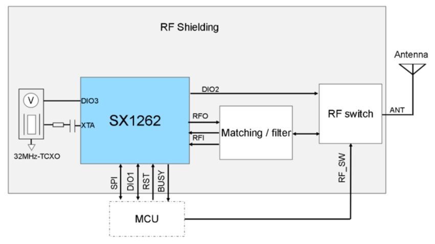
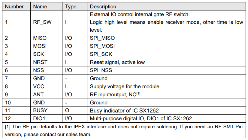
The trick with this Module is the DIO1
DIO1 = GPIO 39 — this is the interrupt line from the SX1262 for RX done events in this case You have several conditions, the main ones being Transmit, Receive & timeout, there’s more.
same things apply , keep the ISR’s short and sweet Set flags and return (no Printing) wait for that in other places.
If you want more granular control, you can use:

radio.setPacketReceivedAction(callback);  // older versions or custom logic

But the standard setDio1Action() is sufficient for 95% of cases, especially for PING/PONG, beacon, or open receiver logic.

AMA,

HTH
GL :slight_smile: PJ :v:

Here is the serial output for clearer view;

// REV 5.4e - SX1262 Open Receiver for Beacon Monitoring
// Board: ESP32-S3 with SX1262 LoRa Module
Initializing SX1262 LoRa radio... SUCCESS!
Listening for LoRa messages...

Received: Seeed Studio
  RSSI: -110.00 dBm	SNR: 5.25 dB
.  RSSI: -110.00 dBm	SNR: 6.00 dB
........  RSSI: -109.00 dBm	SNR: 6.50 dB
.  RSSI: -110.00 dBm	SNR: 6.00 dB
...  RSSI: -109.00 dBm	SNR: 6.00 dB
.....  RSSI: -110.00 dBm	SNR: 6.00 dB
.  RSSI: -109.00 dBm	SNR: 6.50 dB
..  RSSI: -107.00 dBm	SNR: 7.50 dB
..  RSSI: -109.00 dBm	SNR: 6.75 dB
.  RSSI: -106.00 dBm	SNR: 8.50 dB
................  RSSI: -106.00 dBm	SNR: 8.00 dB
.  RSSI: -106.00 dBm	SNR: 8.50 dB
.....  RSSI: -106.00 dBm	SNR: 8.00 dB
.....  RSSI: -106.00 dBm	SNR: 8.50 dB
.............................
..........  RSSI: -107.00 dBm	SNR: 7.75 dB
.  RSSI: -117.00 dBm	SNR: -0.75 dB
.  RSSI: -115.00 dBm	SNR: 1.00 dB
.  RSSI: -115.00 dBm	SNR: 1.50 dB
...  RSSI: -114.00 dBm	SNR: 2.25 dB
.  RSSI: -115.00 dBm	SNR: 1.25 dB
...  RSSI: -114.00 dBm	SNR: 1.50 dB
.  RSSI: -115.00 dBm	SNR: 1.25 dB
...........  RSSI: -115.00 dBm	SNR: 1.75 dB
..  RSSI: -114.00 dBm	SNR: 1.75 dB
.  RSSI: -115.00 dBm	SNR: 1.50 dB
..............  RSSI: -115.00 dBm	SNR: 1.00 dB
...  RSSI: -117.00 dBm	SNR: -0.75 dB
.  RSSI: -117.00 dBm	SNR: -1.25 dB
.  RSSI: -119.00 dBm	SNR: -2.50 dB
.  RSSI: -118.00 dBm	SNR: -2.25 dB
.  RSSI: -118.00 dBm	SNR: -1.75 dB
.  RSSI: -110.00 dBm	SNR: 5.50 dB
.  RSSI: -106.00 dBm	SNR: 8.50 dB
...........  RSSI: -108.00 dBm	SNR: 6.75 dB

Beacon Sender;

// REV 5.4a - SX1262 Beacon Sender with TX Power Toggle
// Board: ESP32-S3 with SX1262 LoRa Module
Initializing SX1262 LoRa radio... SUCCESS!
TX Power set to 22 dBm
................................................................................
.............TX Power changed to 10 dBm
..............................................TX Power changed to 22 dBm
.............

If you were to count all the dots it lines up with the Power level changes… Very Cool :sunglasses:

Latest run with stable setup, 10dB :+1:

// REV 5.4e - SX1262 Open Receiver for Beacon Monitoring
// Board: ESP32-S3 with SX1262 LoRa Module
Initializing SX1262 LoRa radio... SUCCESS!
Listening for LoRa messages...

Received: Seeed Studio
  RSSI: -106.00 dBm	SNR: 8.50 dB
.  RSSI: -102.00 dBm	SNR: 10.25 dB
........  RSSI: -103.00 dBm	SNR: 10.25 dB
.  RSSI: -102.00 dBm	SNR: 10.25 dB
..  RSSI: -103.00 dBm	SNR: 10.50 dB
.  RSSI: -103.00 dBm	SNR: 10.00 dB
.  RSSI: -102.00 dBm	SNR: 10.25 dB
.  RSSI: -103.00 dBm	SNR: 10.25 dB
...  RSSI: -102.00 dBm	SNR: 10.25 dB
.  RSSI: -103.00 dBm	SNR: 10.25 dB
..  RSSI: -102.00 dBm	SNR: 10.25 dB
.  RSSI: -103.00 dBm	SNR: 10.25 dB
.  RSSI: -102.00 dBm	SNR: 10.25 dB

You can always add stuff like :face_with_hand_over_mouth:

  • Log the data to SD or Serial plotter
  • Expand the receiver for multiple beacons
  • Trigger events based on signal quality
  • Add encryption/auth checks
  • Or build a GUI on PC or display!

:v:

1 Like

I am preparing for a long distance communication experiment. In an attempt to find the limits of RSSI and SNR, I have attached a 50 ohm non-inductive load instead of an antenna, shielded it with a biscuit tin, and am making measurements.
The limits of RSSI and SNR seem to be around -127dBm and -15dB respectively.
The sketch is written using MG24, but could easily be modified for other XIAOs.
POST_SX1261_MG24_P2P.zip (8.5 KB)

1 Like

On a related note, I’d like to report that the XIAO ESP32S3 and Wio-SX1262 combo (when connected by the B2B connector) surprisingly does work with the Seeed Round TFT Display. I only tested it with the TFT_Clock example sketch, but both drawing to the screen and touch input worked while intermittently transmitting and receiving LoRa. I am very surprised that this worked, but hey I’ll take it!

1 Like