Hi, I’m trying to use a Xiao nRF52840 to drive an e-paper display panel, and I have the panel’s Vcc pin connected to the Xiao’s 3V3 pin (the panel takes 2.5V to 3.6V, with 3.3V being the typical supply voltage).
If I power the Xiao with USB, the display works. If I power it by supplying 5V to the 5V pin, the display also works. But if I connect a LiPo battery (currently supplying 4.1V) to the BAT terminals, I can see that my code on the Xiao runs, but the display doesn’t work. There is 3.3V on the 3V3 pin, as expected. And same if I just directly supply 3.3V to the 3V3 pin–my code runs, but the display doesn’t.
Any ideas why this is happening? I see from the schematic that both Vbus and Vbat go to the 3.3V regulator and that 3.3V goes to power everything else. So it seems like there should be no difference if I supply 3.3V directly or have Vbus get converted down to 3.3V.
So I’ve already checked that power is getting to the display panel; I guess my next step can be to see if what’s being sent over the SPI data lines is correct, but I don’t get how that would change depending on how the Xiao is powered.
Edit to add: while I haven’t checked the data going to the display yet, I did find that if the Xiao is powered on or reset while being powered with 5V (either USB or the 5V pin), I can disconnect the 5V and leave it powered by the battery, and everything still works.
Hi,
I apologize for being late. What is your intended use case? What size e-paper display do you need to drive? E-paper has specific startup current requirements, and if these are not met, it may not function properly.
I just want to show pictures on the display. It’s a Waveshare 5.65 inch 7-color panel. If the problem was current, wouldn’t that show up when powering via USB, since current could be limited by the 3.3V regulator? But not when powering directly via the 3V3 pin, since the panel is getting its power directly from the power supply (which can supply enough current… the same supply set to 5V can power everything when connected to the Xiao’s 5V pin).
No, I’m using Waveshare’s driver board, which I’ve been using for a while (I’ve had my project working with an Arduino Nano 33 BLE, but wanted to see if I could switch to the Xiao nRF52840)
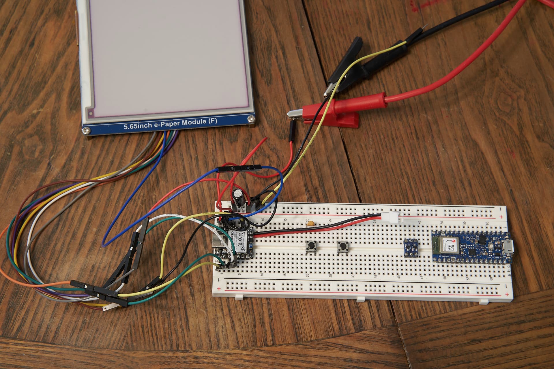
Can you post a picture of the setup?, You’re close it will work.
stay with it. (worth it for the sleep current 2~4 uA)
You may need a capacitor on the display Power line. the start up current is substantial , you won’t get a good POR (power on reset in the display)
the other methods of power connection you tried allow for Higher inrush current than the Lipo circuit (battery charger may be getting in the way) the limit on charge current.
Your last edit , Kinda bears that out…
HTH
GL PJ
ps, I think waveshare has some info on this on their forum.
I don’t like to use the 3.3v pin on Xiao to power anything but Temp/Humid sensors real light loads with no startup slurp job YMMV
You can try to power up the Xiao with the LiPo battery while also connecting the USB (or 5V).It will ensure the regulator receives a good initial voltage to stabilize. Once the system is running, disconnect the USB or 5V to see if it continues working.
Sure, it’s hard to see where all the wires go though. Here are the pin connections
5V: power supply red lead
GND: breadboard - rail, display GND
3V3: breadboard + rail
MOSI: display DIN
SCK: display CLK
D0: display CS
D1: display DC
D2: display RST
D3: display BUSY
The breadboard + rail is connected to display VCC. The breadboard - rail is connected to the power supply black lead. There’s a 440µF 10V capacitor across the breadboard +/- rails.
To simplify the scenarios, let’s just look at supplying 5V and 3.3V from a bench PSU, with no USB or battery involved at all.
https://azeotrope.org/xiao_epaper5v.mp4 shows it being powered with 5V. The Xiao LED turns blue when my code starts running, then yellow after it’s sent the command to clear the display and while it’s waiting for the display’s BUSY line to become non-busy. You can see when it turns yellow, the display starts to flash.
Then https://azeotrope.org/xiao_epaper3v3.mp4 shows it with the PSU set to 3.3V and connected to the breadboard + rail. The only changes are that the PSU red lead has been moved from the red wire that goes to the 5V pin to the yellow wire that goes to the breaboard + rail, and the PSU voltage set to 3.3V. Nothing is connected to the 5V pin. You can see the LED turn yellow, showing that it’s sent the clear display command, but nothing happens to the display.
You may need a capacitor on the display Power line
Yeah, I have one.
battery charger may be getting in the way
I wouldn’t think that the charger would be involved when not charging. The VBAT just goes through the MOSFET for power path selection and then to the 3.3V regulator, right? But in any case, the problem occurs when powering with an external 3.3V source, so neither the charger IC nor the 3.3V regulator are involved.
OK, so check out the E-ink Demo I have on here,
may or may not add anything useful
I think you need to toggle a pin before the reset or something, let’s see the code, You are using the SPI interface pins, some of the pins derive their power from different power group sections of the chip. perhaps that is only resolved if you toggle the Pins first before you use a “begin spi” type situation. If any of that makes sense to you. I had to do something similar if I recall to finally get it to work, or added a delay in the setup to give the slow interface a chance I think
nice screen! I know we have heard of people having problems when powering thru the 5v and 3.3v pins… I have always said the 3v3 pin is designed as a supply not a point of intake… but people call me a lier and dumb all the time…
I cant think of any reason the power would do this other that a voltage - current issue… you already checked the while serial thing so as long as the processor is working and not hung in a setup loop… it must be power… if you have a variable power supply try applying 5v on the pin and letting the internal regulator produce the 3v3
I found the problem! It didn’t seem like a power problem (i.e., wrong voltage or not enough current) to me, since it fails even when providing both the Xiao and the display with 3.3V from a power supply that has plenty of current.
The nRF52840 has 4 SPIM peripherals, with SPIM0 through SPIM2 supporting a max clock frequency of 8MHz and SPIM3 supporting 32MHz. And the Seeed nRF52 board library for the Arduino IDE uses SPIM3 for SPI (search for SPI_32MHZ_INTERFACE at Adafruit_nRF52_Arduino/libraries/SPI/SPI.cpp at master · Seeed-Studio/Adafruit_nRF52_Arduino · GitHub). I read that since SPIM3 supports higher speeds, it requires that the high frequency clock be enabled, and that some other code (I think in the bootloader?) enables it if Vbus is present on reset, but if not, the HFCLK is off and SPIM3 doesn’t work. I haven’t tried it myself, but it should be possible to enable HFCLK in my code.
What I have tried myself is editing SPI.cpp to #define SPI_32MHZ_INTERFACE 1, so it uses SPIM2 instead. The display panel’s SPI interface can only do 10MHz, so it wouldn’t benefit from SPIM3’s higher speed anyway (SPIM3 can’t do 10MHz; the next supported speed after 8MHz would be 16). And with that change, everything works on battery or USB.
Since there’s no benefit for me to use SPIM3 over SPIM2, and that enabling HFCLK uses (a little) more power, I’d rather just use SPIM2 rather than enable HFCLK in my code. So now I’m looking for some way to #define SPI_32MHZ_INTERFACE 1 without editing the board library file. SPI.cpp checks to see if SPI_32MHZ_INTERFACE is already defined before defaulting it to 0 if not, but I need some way to define it to 1 when SPI.cpp is being compiled. It doesn’t work to put the #define in my sketch before #including SPI.h, since that doesn’t cause it to be #defined when SPI.cpp is compiled. I need a way to pass -DSPI_32MHZ_INTERFACE=1 on the g++ commandline, but I don’t know how to do that. Or I guess I could create my own SPI2 instance of SPIClass and change my code to use SPI2 instead of SPI.
The power domains …will get you sometimes, if you have a look at the adding external flash to the Grove Expansion board Demo I have on here, you’ll see the SpIM tech I used to have external SPI on 2 .
I used the adafruit flash info to build it from and test both internal, onboard and added external chip I added.
HTH
GL PJ
here’s a peek
#define SS_SPI0 1  // default to Pin 7 if you don't declare it as the CS for the Flash Chip A1/D1 pin1 on the Xiao
#define SS_SPI1 25  // Default SS or CS for the Onboard QSPI Flash Chip

SPIClass SPI_2(NRF_SPIM0, PIN_QSPI_IO1, PIN_QSPI_SCK, PIN_QSPI_IO0);  // Onboard QSPI Flash chip
Adafruit_FlashTransport_SPI QflashTransport(PIN_QSPI_CS, SPI_2);      // CS for QSPI Flash
Adafruit_SPIFlash Qflash(&QflashTransport);

SPIClass SPI_1(NRF_SPIM3, D9, D8, D10);                       // MISO, SCK, MOSI /EXPANSION FLASH// CS pin D1 (hardwired)
Adafruit_FlashTransport_SPI EflashTransport(SS_SPI0, SPI_1);  // Flash Type
Adafruit_SPIFlash Eflash(&EflashTransport);