Seeed XIAO BLE Sense nRF52840 deep-sleep mode

Hello.
I bought Seeed XIAO BLE Sense nRF52840 and I’m trying to understand how to switch it to deep sleep mode. On Wiki I read, that I should use this code:

// The MIT License (MIT)
// Copyright (c) 2019 Ha Thach for Adafruit Industries

#include "SdFat.h"
#include "Adafruit_SPIFlash.h"

// Uncomment to run example with custom SPI and SS e.g with FRAM breakout
// #define CUSTOM_CS   A5
// #define CUSTOM_SPI  SPI

#if defined(CUSTOM_CS) && defined(CUSTOM_SPI)
  Adafruit_FlashTransport_SPI flashTransport(CUSTOM_CS, CUSTOM_SPI);

#elif defined(ARDUINO_ARCH_ESP32)
  // ESP32 use same flash device that store code.
  // Therefore there is no need to specify the SPI and SS
  Adafruit_FlashTransport_ESP32 flashTransport;

#else
  // On-board external flash (QSPI or SPI) macros should already
  // defined in your board variant if supported
  // - EXTERNAL_FLASH_USE_QSPI
  // - EXTERNAL_FLASH_USE_CS/EXTERNAL_FLASH_USE_SPI
  #if defined(EXTERNAL_FLASH_USE_QSPI)
    Adafruit_FlashTransport_QSPI flashTransport;

  #elif defined(EXTERNAL_FLASH_USE_SPI)
    Adafruit_FlashTransport_SPI flashTransport(EXTERNAL_FLASH_USE_CS, EXTERNAL_FLASH_USE_SPI);

  #else
    #error No QSPI/SPI flash are defined on your board variant.h !
  #endif
#endif

Adafruit_SPIFlash flash(&flashTransport);


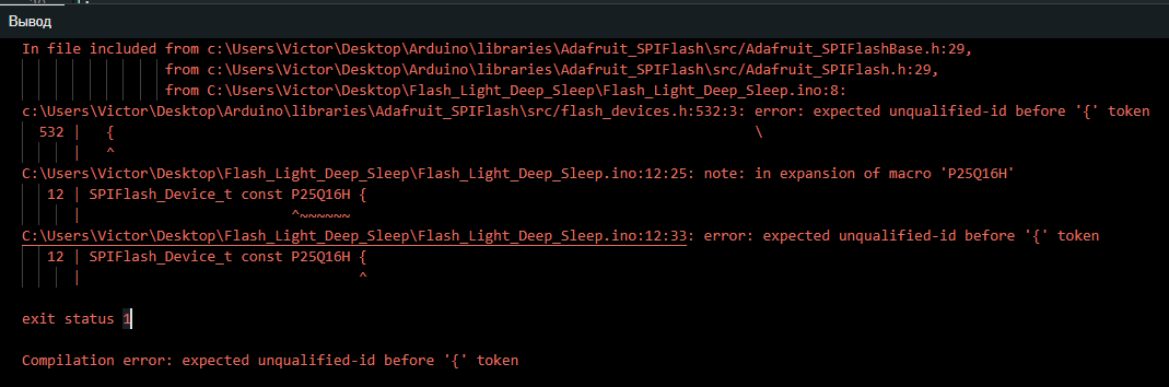
/*  If you want to use a specific flash device, for example for a custom built board, first look for it in Adafruit_SPIFlash\src\flash_devices.h
 *  If it isn't in there you need to create your own definition like the W25Q80DLX_EXAMPLE example below.
 *  These definitions need to be edited to match information on the data sheet of the flash device that you want to use.
 *  If you are not sure what the manufacture ID, memory type and capacity values should be, try running the sketch anyway and look at the serial output
 *  The flash device will report these values to you as a single hexadecimal value (the JDEC ID)
 *  For example, the first device on the list - the W25Q80DLX - will report its JDEC ID as 0xef4014, which is made of these three values:
 *  manufacturer_id = 0xef
 *  memory_type     = 0x40
 *  capacity        = 0x14
 *  With this macro properly defined you can then create an array of device definitions as shown below, this can include any from the list of devices in flash_devices.h, and any you define yourself here
 *  You need to update the variable on line 71 to reflect the number of items in the array
 *  You also need to uncomment line 84 and comment out line 81 so this array will be passed to the flash memory driver. 
 */
//Example of a user defined flash memory device:
//#define W25Q80DLX_EXAMPLE                                                               \
//  {                                                                            \
//    .total_size = (1 << 20), /* 1 MiB */                                       \
//        .start_up_time_us = 5000, .manufacturer_id = 0xef,                     \
//    .memory_type = 0x40, .capacity = 0x14, .max_clock_speed_mhz = 80,         \
//    .quad_enable_bit_mask = 0x02, .has_sector_protection = false,              \
//    .supports_fast_read = true, .supports_qspi = true,                         \
//    .supports_qspi_writes = false, .write_status_register_split = false,       \
//    .single_status_byte = false, .is_fram = false,                             \
//  }

/*
 * Create an array of data structures and fill it with the settings we defined above.
 * We are using two devices, but more can be added if you want.
 */
//static const SPIFlash_Device_t my_flash_devices[] = {
//    W25Q80DLX_EXAMPLE,
//};
/*
 * Specify the number of different devices that are listed in the array we just created. If you add more devices to the array, update this value to match.
 */
//const int flashDevices = 1;


#include <bluefruit.h>
void setup()
{
  flash.begin();
  Bluefruit.begin(); 
  if(flash.deepPowerDown() == false){
    pinMode(LED_BUILTIN, OUTPUT);
    digitalWrite(LED_BUILTIN, LOW);
    while(1)
    {
      yield();
    }
  }
  flash.end();

  sd_power_system_off(); 
}

void loop()
{
  // nothing to do
}

As I understand, this code for old versions and now it doesn’t work. So please help me figure out how can I activate deep speed mode?
I tried juse use:

NRF_POWER->SYSTEMOFF = 1;

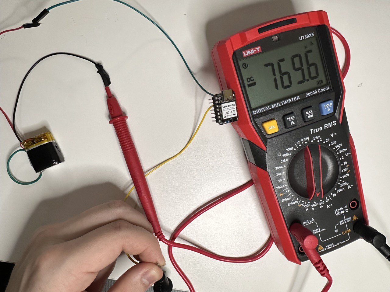
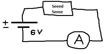
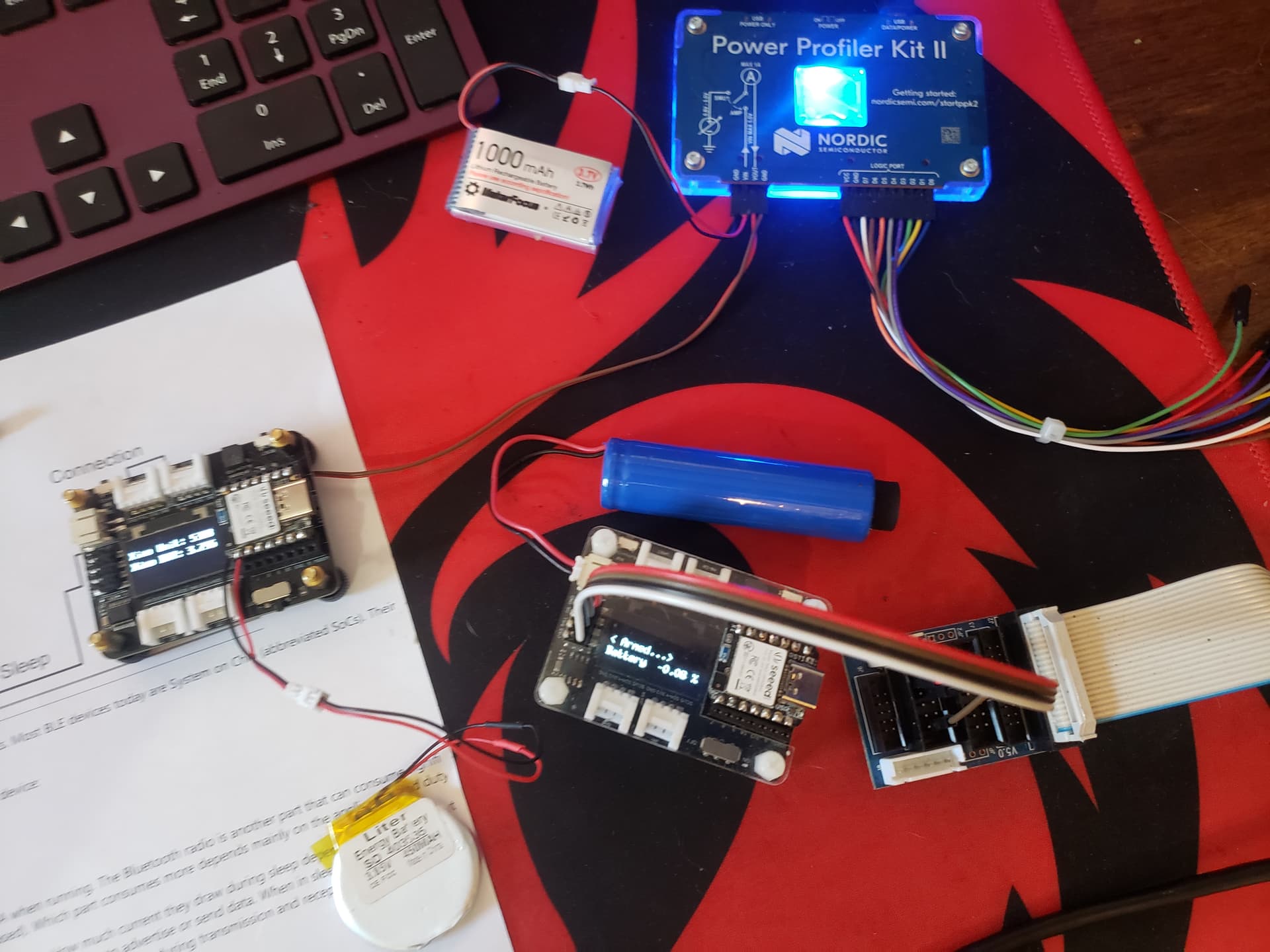
But it doesn’t work (current around 5-6 mA, I expect < 20 mkA).
Thanks for help!

Hi there,
In a word. Keeep reading. :slight_smile:
Msfujino has completely sussed it out and has some of the best documented methods and hard data on what works and what doesn’t , use the search above and you will be rewarded.
HTH
GL :slight_smile: PJ

1 Like

Hi Vint1k,
Please read the link below.

1 Like

@msfujino, thank you for help.
I copied your code and attempted to activate deep sleep mode, and it worked!
However, I may have made a mistake because when I took measurements, the current was around 700 μA.
Based on your comparison, the current should be around 5-25 μA, which is ten times lower.

I have one more question for you.
If I enable deep sleep mode, how can I wake up the device? I’ve read something about GPIO, but as a beginner, I don’t really understand how to implement it.
I have a button. Is it possible to wake up my device by pressing this button?

Hi there,
So which BSP files did you use? that makes it better on order of magnitude. Embed andNON-mbed
the first line of the compiler output will tell you if you’re not sure which board you picked, there’s two choices same MCU (currently non-mbed is Ver. 1.1.8 the embed one is 2.9.2.) the most power saving was with the first one NON-embed.
HTH
GL :slight_smile: PJ

1 Like

Hi again.
Here is the output when compiled:


As far as I understand, I currently have non-mbed. And you say that this BSP is the most efficient in terms of energy saving mode. It seems like there’s something wrong with my board…

Hi there,
Yes I believe, all the Power is saved mostly in BSP 1.1.1 Try roll back and measure again.
HTH
GL :slight_smile: PJ

I tried to roll back to version 1.1.1.
At first I encountered an error saying that the file “Adafruit_SPIFlash.h” was not found.
Next, I installed the “Adafruit SPIFlash” library and encountered the following error:


I suspect that I also need to install not the latest version of Adafruit SPIFlash. Which one then?

upd. I rolled back this library to version 4.0.0 - the current consumption became 80 MILLIamperes. So many. I never had this before, even without a sleep schedule…

Hi there,
If you look at the demo I posted for the Grove Expansion Board on here, there is the Compiler output that shows which version, Pretty sure it’s the latest , but check it out for the correct implementation of it.
I put the flash params in the code as opposed to having the .h flash conf_file.
HTH
GL :slight_smile: PJ

1 Like

I re-measured it under the following conditions and it sleeps without problems.

//----------------------------------------------------------------------------------------------
// BSP : Seeed nRF52 Borads 1.1.8
// Board : Seeed nRF52 Borads / Seeed XIAO nRF52840 Sense 
//----------------------------------------------------------------------------------------------
// 2024/02/14

#include <bluefruit.h>          // 1.10.0  /Arduino15/packages/Seeeduino/hardware/nrf52/1.1.8/libraries/Bluefruit52Lib/src
#include <Adafruit_SPIFlash.h>  // 4.3.1 or earlier   Need to be deleted /Documents/Arduino/libraries/SdFat

When connected to USB, charging current is observed, but 80mA is not charging current?

2 Likes

Hi there,
That’s GREAT! thanks msfujino… Progress :+1:
GL :slight_smile: PJ
I had initially between 60ma and 80ma with BLE & Flash and external darlington mosfet driver for a solenoid on my rev 1 pc board. that’s high(80ma) on any planet…

Hi there.

Firstly, thank you so much for your assistance.
How do I measure current? I upload the sketch to the Arduino board via USB cable in ArduinoIDE, then disconnect the board from the computer and connect it to a power source (approximately 6V DC). Here is the electrical circuit:
Без имени
Next, I simply measure the current with a regular multimeter (I sent a photo of how I measure the current just above).
But now it seems that I’ve burnt out the multimeter, as it no longer measures milli- and microamps.

Therefore, I am unable to check the current now (using the versions of the libraries that msfujino provided).
msfujino, how do you measure the current?

I truly aim to achieve a current around tens of microamps!

I use pppk2.
Power Profiler Kit II - nordicsemi.com

1 Like

Hi there,
Best money ever spent, Does so much more than just measure and log power, sources it , sinks it, and has built in mini logic probes…Allows you to visualize Signals and Power consumption as it relates to Code development. :wink: :ok_hand:


one of theses…

HTH
GL :slight_smile: PJ

also while we are here, The $10 nordic Dongle is the best BLE test tool available. (and it’s programable)


all of it works from the Nrf_Desktop app… download it Awesome

1 Like

Thank you.
Already ordered Nordic Dongle, and ppk2.
I’ll test it. As far as I understand, the Nordic Dongle will need to be programmed using the nRF Connect SDK?
There will also be questions regarding deep sleep…)

Hi there,
The Nrf_desktop app , will recognize the device and drop code on it for the tool needed.
You don’t do anything but confirm… :+1: Works really Great!
HTH
GL :slight_smile: PJ

1 Like

Thank you, you help me a lot!
If you allow me, I’ll ask one more question.
According to my plan, the device should connect via Bluetooth (probably BLE) to a mobile phone. And I want to be able to upload a new sketch (in fact, a firmware update) to the board from my mobile phone. Is this possible?
(I’m talking about the Seeed XIAO BLE Sense nRF52840 device now)

Hi there,
Yes Under certain Circumstances.
You need to put it into Bootloader Mode (usb-C) or Use a form of BLE OTA (Over the Air Update)
The later is somewhat restrictive, over the air.
The sketch would be in the form of a u2f file or Hex
Check the Over the Air updates threads for Nordic also, You set aside an area in Flash to drop the bin onto then it reboots to that, not sure if it’s permanent (lost at next power cycle?) update unless you do something b4 hand.
HTH
GL :slight_smile: PJ

AFAIK, there is a working example in the Nrf_SDK , but I may be wrong.

1 Like

First of all, I am very grateful to you for trying to help me.
I explain the situation I am in. I’m now trying, firstly, to understand what to use: it’s either Arduino or nRF SDK / nRF Connect.
I need to find a suitable option, taking into account my wishes:

  • Possibility of realizing deep sleep with a consumption of less than 100 microamps.
  • Ability to update firmware via Bluetooth Low Energy from a mobile phone.
  • Ability to connect and work using the Ant+ protocol.
  • Ability to work with third-party devices (in my case, with the AS5600 magnetometer).

I’m new to this topic. As far as I thought to myself before, there will be fairly simple examples for each point that will help me decide, and so on.
But even with the first point (deep sleep), I already had problems. No matter how hard I try, repeating all your actions, I cannot achieve a consumption of 100 μA or less.
I asked a question regarding Ant+ in a separate topic, to which you answered that I needed to use OTA downloading, but I didn’t get any really working measurements.
There are no problems with AS5600 on Arduino, but when it comes to nRF connect / nRF SDK, I’m sure I’ll have to “reinvent the wheel.”

Now let me get to the heart of the matter.
Is this really such an unexplored topic that there are no ready-made solutions, examples, or tips?
As an example, uploading the S340 to Seeed Sense - I’m sure I’m far from the first to do this. Is there really no step-by-step instructions on how to download? (this is for Ant+)
Or, for example, an OTA update - I started reading, but there is not a single ready-made example.

Don’t get me wrong, I really appreciate the time allocated for me, but, unfortunately, I haven’t found any specific solutions for myself. I will be EXTREMELY GRATEFUL if you find a solution for me on Arduino for at least one of the above points. And yes, I’m currently considering Arduino as my main option, so please don’t suggest nRF connect to me. If I understand that it is difficult to implement this on Arduino, but easier on nRF connect, then, of course, I will switch. But you understand me, I cannot implement some of them this way and some of them differently. I need to implement everything on one framework.

I’m even willing to pay if people help me with ready-made codes and IDE settings that solve at least one of the listed problems.
Because at the moment there are only more questions, but, unfortunately, I have not yet been able to close a single question, I have not found a single final solution.

Thank you very much!

Hi there
Sure, We are all here to help. What you endeavor to do , is NEW and therefore no ready made examples are in existence. Does not mean you can’t be the First :wink: :v:
Start with the first this , the SLeep and get that handled, It is very possible.
ton’s of code on here for that.
Do you have a sketch that works with the AS5600?
Post it and let’s start there. Your not the first to face this effort. Takes some patience and work but in the end it’s totally possible.

To your points,
Deep Sleep , Light Sleep (Done, level of power savings depends on BSP file used)
UPdate firmware over BLE. (I have only seen this on the Nordic SDK, but it is possible)
Ant+ protocol (work in process, needs first two)
AS5600 absolutely. doable and probably done already.

I would work it in reverse maybe, get the comms working, then do the rest.
you using this hardware?

HTH
GL :slight_smile: PJ

1 Like