System_ON_Sleep of XIAO BLE

System_OFF_Sleep (Deep Sleep) is used to significantly reduce current consumption, but requires an external trigger for wake-up. On the other hand, System_ON_Sleep can easily woken up using the built-in RTC interrupt. In a project that periodically sends data from a peripheral to the central, I experimented with System_On_Sleep to see how much current consumption of a peripheral XIAO could be reduced.

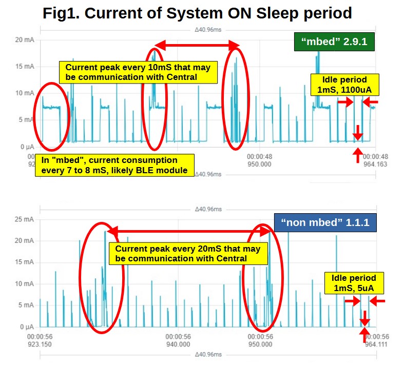
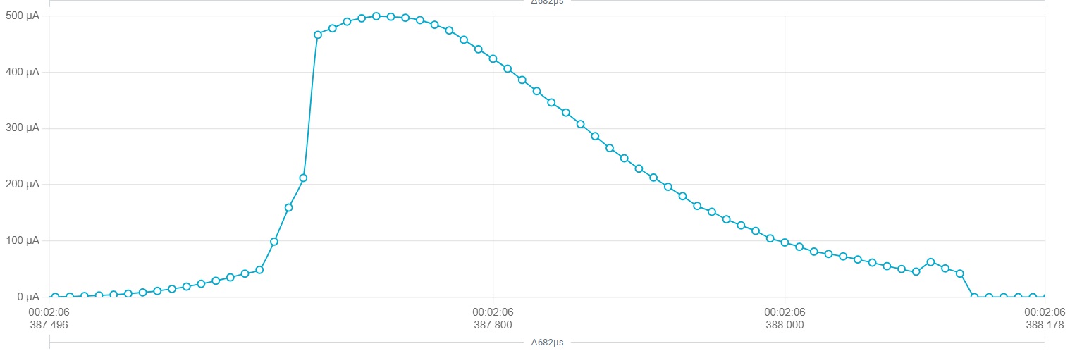
In System_ON_Sleep, the CPU sleeps by the WFI() command, but during sleep, it seems to repeatedly exit the idle state every 1mS, check the requests of modules, supply current to the necessary modules for the necessary time, and return to the idle state. When the RTC interrupt occurs, the CPU wakes up and performs the defined task, then sleeps again by the WFI() command.

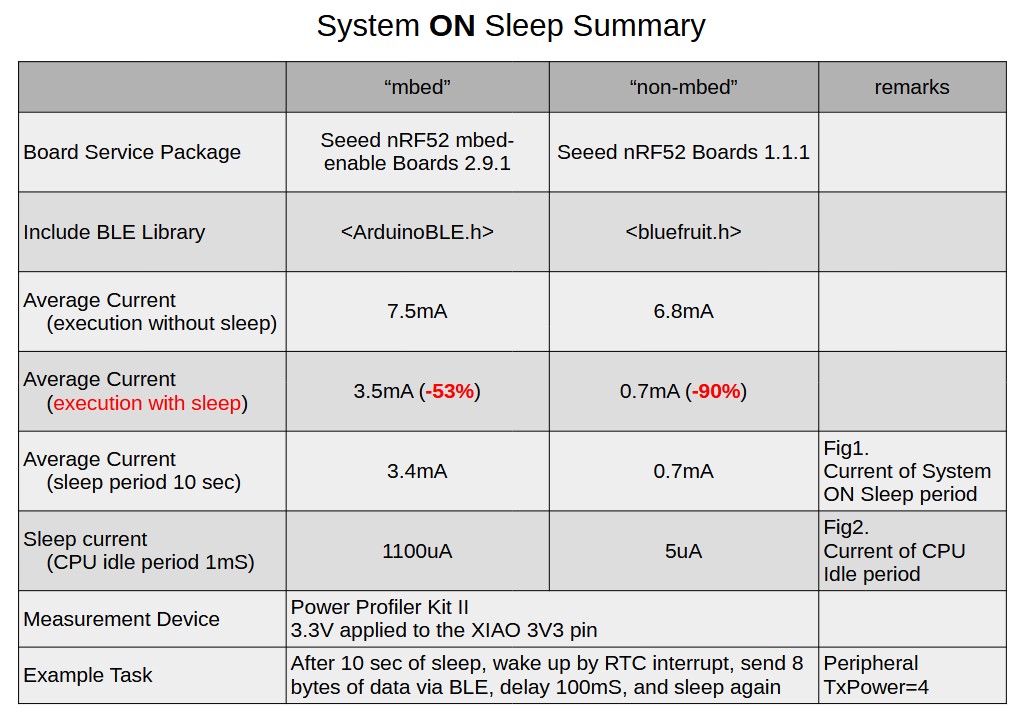
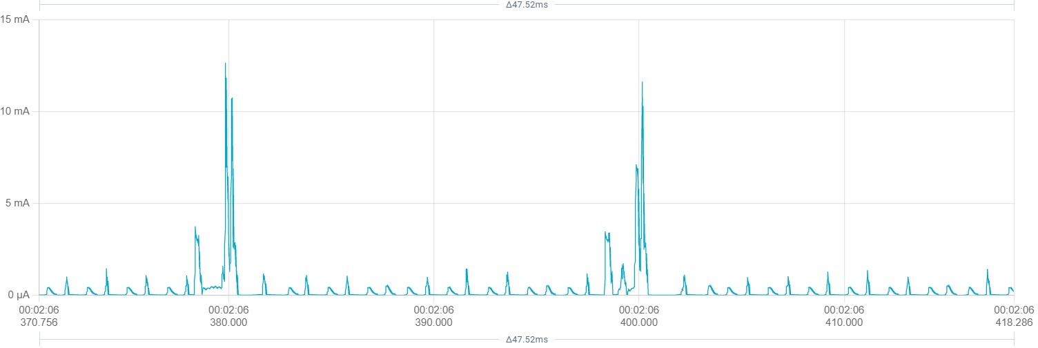
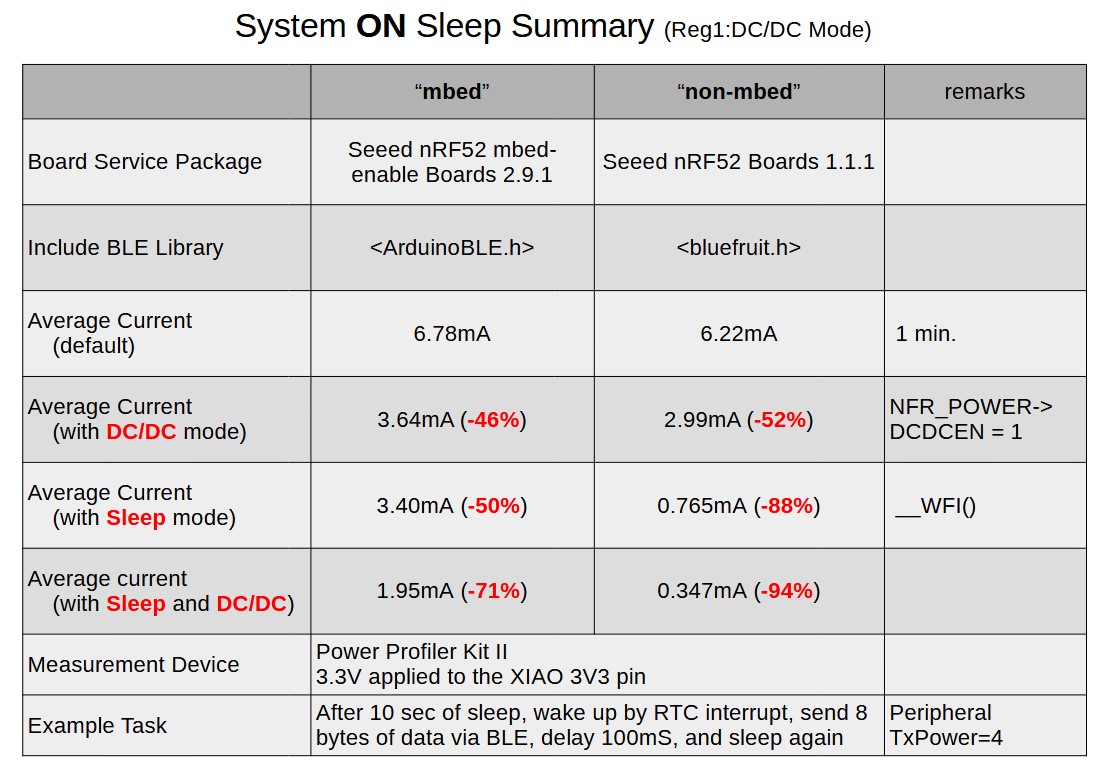
The example sketch is "(1)sleep for 10 seconds, (2)wake up by RTC interrupt, (3)send 8 bytes of data to the central, (4)after 100mS delay, (5)sleep again”.
3.3V was applied to the 3V3 pin of XIAO and the current consumption was measured using PPK2.

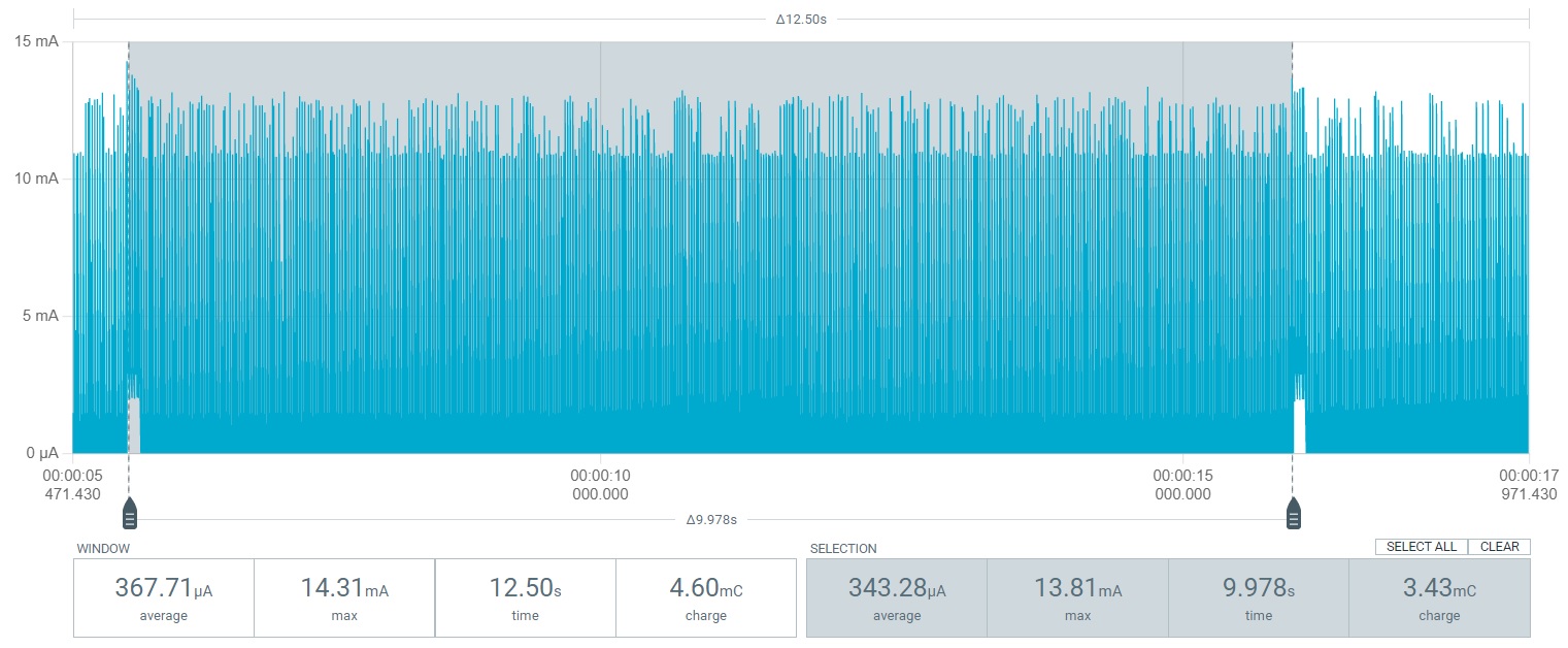
As a result, it was found that 53% of the current can be reduced when using “mbed 2.9.1” and 90% when using “non mbed 1.1.1”.
The reasons why “mbed 2.9.1” is not able to reduce the current are: (1) the radio module is probably powered every 7~8mS even during sleep, (2) the communication frequency with the central is 10mS (“non mbed” 20mS), and (3) the idle current is 1100uA (“non mbed” 5uA).
Reading and verifying these reasons from the source code is unfortunately beyond my capabilities.

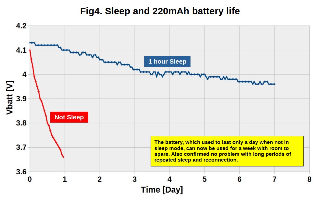
The current reduction effect of “non mbed 1.1.1” is expected to be significant for my project, which involves periodic data transfers.

Here is the sketch used for the measurement.
XIAO_BLE_SystemOnSleep.zip (310.0 KB)

The following documents were used for reference.
Lesson 14 – nRF5x Power Management Tutorial – Embedded Centric
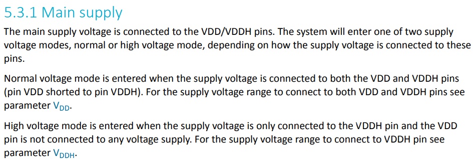
nRF52840 Product Specification v1.1 5.3 POWER — Power supply, 6.22 RTC — Real-time-counter
GitHub - tigoe/BluetoothLE-Examples: BluetoothLE Examples of various platfoms

4 Likes

Another impressive experiment by msfujino, much appreciated.

It seems Adafruit core (based on Free RTOS) performs much better in terms of power efficiency. To what I saw on Adafruit Github, the number of peripheral connection is also higher than Mbed core.

Perhaps it is time to permanently switch to Adafruit core. Thanks again for your sharing.

1 Like

I’ve been using “mbed” because the “ArduinoBLE” library was easier for me to understand than “bluefruit”. “mbed” still has a battery voltage reading bug that has not been resolved, and I’ve found it has poor sleep performance. I am beginning to think that this might be a good time to move away from “mbed”.

1 Like

Nice work!

There are additional tricks that might help in other situations. If you don’t need a main loop at all, you can call suspend_loop() at the end of setup. FreeRTOS will automatically put the system in System_ON_Sleep when possible.

Also, if you have an event based device (e.g. button press) with heavy main loop processing, you can use a FreeRTOS semaphore in the main loop. FreeRTOS will automatically put the system in System_ON_Sleep while it is blocked on the semaphore. Examples here: Getting lower power consumption on Seeed XIAO nRF52840

It seems the power efficiency can be further improved by enabling the on-chip DC-DC converter.

// Enable DC-DC converter
NRF_POWER->DCDCEN = 1;

// RTC initialization
initRTC(32768 * SLEEP_TIME); // SLEEP_MTIME [sec]

// Initialization of Bruefruit class
Bluefruit.configPrphBandwidth(BANDWIDTH_MAX);
Bluefruit.configUuid128Count(15);

The average current of my peripheral improves from 0.57mA to 0.35mA. The peak current seems to be lower, from 25mA to 15mA. I do not have tools on hand to see if the transmit power stays the same. Perhaps I can use a sketch to scan the RSSI of the broadcast packets although this method is not very precise.

1 Like

Thank you all for the helpful information.
According to the schematic of XIAO_nRF52840, it looks like the inductor is implemented, so I can use DC/DC mode!

When I tried DC/DC mode, the average current decreased from 700uA to 560uA with every 10 seconds of wake-up and data transfer.

Do you use source mode or ammeter mode on your PPK2? My measurement waveform is not entirely similar to your posted diagrams.

In source mode, 3299mV is applied to the 3V3 pin.
Transmit power is “setTxPower(4);”.

My measurement feeds 3.7V from PPK2 to the battery pins.


If 3.7V is fed to the battery bads, it passes through the LDO and a large capacitor is also connected, so the current behavior may be different.

Yes this could be the reason. If I understand correctly, the chip has a VDDH pin which allows direct battery connection and saves the external LDO.

Unfortunately we have to live with the external LDO on Seeed board since VDD only tolerates up to 3.6V. We may connect non-rechargeable Lithium battery directly to VDD but we cannot avoid, if it exists, reverse leakage to the LDO.

I got information from hobbya and daCoder about the on-chip DCDC converter and on-board flash memory. I have tried to find out how effective they are together with System_ON_Sleep.

I was able to reduce the current by about half just to get the system into DCDC mode without sleep. Used in conjunction with System_ON_Sleep, I was able to reduce the current by 94% on “non-mbed” and 71% on “mbed”. As expected, using “non-mbed” reduces the current by far. Flash memory OFF was not significantly more effective than the other two, so it was omitted from the data.

Here is the sketch used for the measurement.
XIAO_BLE_SystemONSleep_2.zip (10.5 KB)

An error in the description of the table has been corrected.

Nice work ms !
If the average consumption is a few hundred uA, then shutting down the QSPI flash (~20uA) may not provide prominent results unless the transmission cycle is further reduced to bring down the average consumption.

WOW, Standing on the shoulders of GIANTs, You guys are Bomb!, MS your tenacity and attention to detail is a marvel. Seeed should send you a BIG FAT GIFT for the work you do for them and US.

THANk You…

あなたの努力に感謝します、彼らは私に多くの助けを与えてくれます。以前の投稿をもっとよく見るべきでした。あなたが日本出身だとわかってうれしいです。

Anata no doryoku ni kansha shimasu, karera wa watashi ni ōku no tasuke o ataete kuremasu. Izen no tōkō o motto yoku mirubekideshita. Anata ga Nihon shusshinda to wakatte ureshīdesu.
:wink:
GL :slight_smile:
PJ

@PJ, MS is Japanese :sweat_smile:
お疲れ様でした
ありがとう

1 Like

Thank you all for your encouragement.

It is important not only to reduce the current, but also to be able to wake up and reconnect after a long sleep. I’m now testing to see if the Peripheral can properly reconnect properly to the Central and transfer data after an hour of sleep, it will take a few days, I’ll post the results.

I checked to see if XIAO could wake up and reconnect after a long sleep.
For the experiment, I used a 220mAh battery, XIAO in DCDC mode and on-board Flash in power-down mode, “non-mbed” BSP.
Peripheral sleeps for 1 hour, then wakes up and reconnects with Central, sending 8 bytes of battery voltage and measured time data. Central is always waiting for a connection from Peripheral and writes the data to the SD when received.
The battery, which used to last only a day when not in sleep mode, can now be used for a week with room to spare. I have also confirmed no problem with long periods of repeated sleep and reconnection.
It performs well enough for my application.

Here is the sketch used for the measurement.
XIAO_BLE_SystemONSleep_3.zip (6.8 KB)

1 Like

Wow, Stellar R&D msfujino, Seeed owes you a GIFT basket. there engineering doesn’t even comment which is SAD for them but You are BLE NIJA :ninja: Thank you for the sharing, I’m redoing my stuff for NON-Mbed and hope soon to be converted.
GREAT JOB.

GL :slight_smile: PJ

Inspired by msfujino, I was wondering if the consumption of the peripheral could be further reduced.
Attached are two quick sketches modified from Adafruit examples. The peripheral broadcasts a new set of data every 10s. The central scanner uses the uuid to filter the packets coming from the peripheral. No connection phase between the 2 devices are involved, only advertise and scan. As a result duplicated packets will be picked up by the central. The average current of the peripheral gets lower as the data exchange becomes 1-way instead of 2-way and no interrupt routines are needed. The peripheral advertises for 5s and then sleeps for 5s. Sleep time can be extended by changing the delay value in the loop.
NRF52840.zip (2.6 KB)
I also use the NRFconnect mobile app to scan the packets from the peripheral. It is a good tool and helps me understand the construction of the packets.
The attachment is only a simple demo. An advertising packet carries up to 31 bytes. If user wants to advertise more data bytes, he can enable active scan on the central. The extra data bytes can be transmitted by the peripheral as a scan response packet. This should suffice most sensor applications.

1 Like