I’m using the XIAO MG24 and I’m comparing the power consumption between the Silicon Labs development board DBG1015A and the MG24. I’m using Simplicity Studio to flash the blinky app.
The values I’m seeing now are:
DBG1015A: 0.177mA
MG24: 0.550mA
I would presume that we could lower the power usage of the MG24 to the same level of the DBG1015A. The same app, the same code. What can I do to get a lower power usage on the MG24?
I would think they would be the opposite, SMH?
As some would argue, there’s not a lot of GOOD info out there.
From looking and testing I would suggest you check the basics first,
the Oscillators (LFXO or LFRC) are they set the same?
Power management settings is SimpStud…
Sleep modes there are 4, don’t ask why.
Floating , or undefined GPIO’s = High Leakage current in SIL parts well documented.
Check if the regulators used are the same, just for grins.
Sounds to me like some lower power management settings are turned on by default on the Dev board. The bare silicon doesn’t have that maybe or it’s just not enabled. (are peripherals turned off?)
Hi Tom,
I’ve been doing some testing and have not been able to get the XIAO_MG24 to run at less than 80uA in Sleep Mode (EM2) using Simplicity Studio (Silabs’ SDK 2024.12.1) code.
This is using a Silabs Zigbee Sleepy End Device app. With this current consumption however, I probably wouldn’t be using the XIAO MG24 as a “Zigbee/BLE battery low power” device. ~5uA is the norm (MG24 EM2). I could however use it as a Zigbee Green Power device - may try that later…
I don’t bother with unused pins; Silabs’ EFR/EFM chips don’t require setting mode or state if unused, and leakage is nA.
I do disable the on-board devices and place the flash into shutdown state.
My Setup.
Power is 3.7V from the battery pads.
Obviously the USB-Serial is disconnected.
My Wake Pin is PA5 (for both EM2 and EM4 wake).
Flashing (SWD) and Energy Profiling is done with the Silabs WSTK.
LOL, I wouldn’t want to spoil your fun. You get some more experience , you’ll know Silicon Labs has published several application notes on low-power design and optimizing leakage currents with their EFR32 series.
For example, an application note (or Low Energy Guide) might explain that unused pins should be tied to a known state (by configuring them as outputs or enabling internal pull-ups/pull-downs) to minimize leakage.
I don’t want to spoiler alert you but it’s your parade (TSMC my Guy) 40 and 65 mm process, You ever worked in a FAB? I have. LOL and this phenomenon is indeed documented in Silicon Labs’ documentation for the EFR32MG24 (MG24) series. Here are some pointers on where and how this is documented:
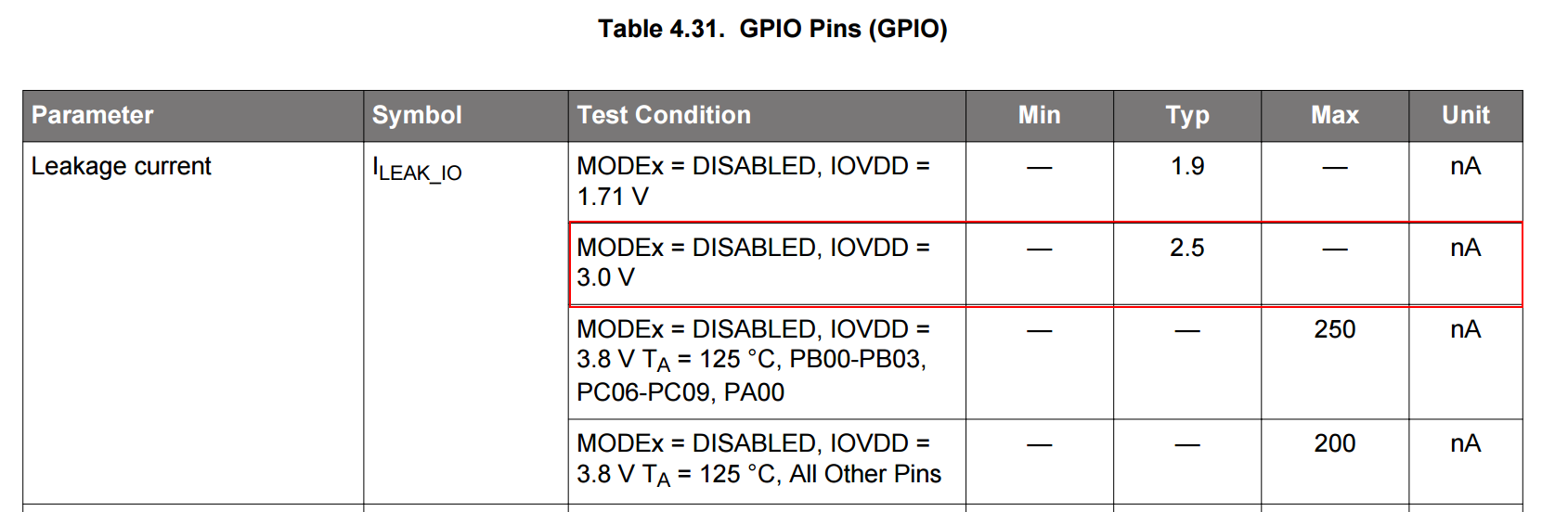
In the EFR32MG24 datasheet, there is a section on “Electrical Characteristics” Section 4 , 4.2 in your DATAsheet link or “I/O Characteristics” that specifies leakage current levels for GPIO pins in various configurations (e.g., when configured as an input with no defined level versus when pulled high or low). This section will note that leaving inputs floating can result in higher leakage currents. (as a Technician you know this)… and FYI…
The reference manual for the MG24 does also discuss recommended practices for configuring unused I/O to avoid unnecessary power drain. Look for sections that cover GPIO configuration or best practices for low-power designs.
Just look with your eyes at what you posted (3.0v IOVDD) what a dead battery, C’mon man! you see the OTHER numbers in that chart ? The MAX ones? Wouldn’t you saying it’s only 1 or 2 na, be NOT true, could go as High as 250na. just saying… LOL
it’s your chart.
I get you’re being funny with posing the same form and ? but YOU really should do your own homework first. Just like the life safety certs, they don’t HAVE!
There aren’t “bugs” per se that make Silicon Labs SoCs unusable in low-power designs, but there are several well‐documented challenges and nuances you need to be aware of. They are NOT on a NEON sign anyware, For example:
Floating Inputs and Leakage Currents:
The datasheets and application notes (for instance, in the EFR32MG series documentation) repeatedly emphasize that unused GPIO pins must be configured (for example, with internal pull-ups or pull-downs or set as outputs) because leaving them floating can lead to higher leakage currents.
DC‑DC Converter Configuration:
Some Silicon Labs SoCs are designed to work with an on‑chip DC‑DC converter to reduce quiescent current in low‑power modes. If the converter isn’t enabled or properly configured, the device may draw significantly more current than expected in sleep modes. Silicon Labs’ low‑energy design guides describe how to configure these regulators properly.
Peripheral Shutdown:
Not disabling unused peripherals (or leaving them in a default state) can lead to higher power consumption. Documentation and application notes recommend explicitly shutting down or reconfiguring peripherals that aren’t needed during deep sleep.
Errata and Silicon Revision Nuances:
Like all semiconductor products, early silicon revisions of Silicon Labs SoCs sometimes have errata that affect power consumption. These issues are documented in the “Errata” documents available from Silicon Labs. Have you ever looked at one? I’m betting NO, and you probably don’t know where to look either. “Users are advised to check the latest errata for their specific SoC revision to ensure that any known issues are accounted for in their design”. E101
Board-Level Design Considerations:
Sometimes the additional current draw isn’t just from the SoC itself but from supporting components on the board (such as voltage regulators, decoupling, etc. just ask seeed ).
Ok, NOW! You have my rhetorical answer. the horse is dead.
GL PJ
Now let’s see how long they take to fix reading the battery voltage.Tick/Tock
Hi tompesman,
Please refer to the measured current consumption of XIAO_MG24.
3.8V was applied to the battery pad and measured with pppk2.
Using ArduinoIDE2.3.4, BSP2.3.0, Protocol Stack “None”,
Current consumption was 453uA. When the onboard peripherals were explicitly turned off, the current consumption was 445uA.
//----------------------------------------------------------------------------------------------
// BoardBoard Library : Silicon Labs 2.3.0
// Board Select       : Seeed Studio XIAO MG24 (Sense)
// Plotocol stack     : None
//----------------------------------------------------------------------------------------------
// 2025/02/23

// ********************************
#define PERIPH_OFF
// ********************************

// on board Flush SPI_1 pins
#define CS1      PA6   // (21)
#define CLK1     PA0   // (17), D17
#define MOSI1    PB0   // (15), D15
#define MISO1    PB1   // (16), D16

// on board peripherals pins
#define IMU_EN   PD5   // (19)
#define MIC_EN   PC8   // (22)
#define VBAT_EN  PD3   // (25)
#define RFSW_EN  PB5   // (27)

// Flash commands
#define READ_DATA     0x03
#define WRITE_ENABLE  0x06
#define PAGE_PROGRAM  0x02
#define SECTOR_ERASE  0x20

// Flash functions
void sendSPI(byte data) {
  for (int i = 0; i < 8; i++) {
    digitalWrite(MOSI1, data & 0x80);
    data <<= 1;
    digitalWrite(CLK1, HIGH);
    delayMicroseconds(1);
    digitalWrite(CLK1, LOW);
    delayMicroseconds(1);
  }
}

void writeEnable() {
  digitalWrite(CS1, LOW);
  sendSPI(WRITE_ENABLE);
  digitalWrite(CS1, HIGH);
}

void setup()
{
  // builtin LED
  pinMode(LED_BUILTIN, OUTPUT);
  digitalWrite(LED_BUILTIN, HIGH);

#ifdef PERIPH_OFF
  // on board flash pins
  pinMode(CS1, OUTPUT);
  pinMode(CLK1, OUTPUT);
  pinMode(MOSI1, OUTPUT);
  pinMode(MISO1, INPUT);
  digitalWrite(CS1, HIGH);   // CS1 HIGH

  // on board peripherals OFF
  pinMode(IMU_EN, OUTPUT);
  pinMode(MIC_EN, OUTPUT);
  pinMode(VBAT_EN, OUTPUT);
  pinMode(RFSW_EN, OUTPUT);
  digitalWrite(IMU_EN, LOW);   // IMU Power OFF
  digitalWrite(MIC_EN, LOW);   // MIC Power OFF
  digitalWrite(VBAT_EN, LOW);  // VBAT Power OFF
  digitalWrite(RFSW_EN, LOW);  // RFSW Power OFF

  // on board Flash Deep Power Down
  writeEnable();
  digitalWrite(CS1, LOW);
  sendSPI(0xB9);
  digitalWrite(CS1, HIGH);
  delay(1000);
#endif
}

void loop() {
                                      //          PERIPH_OFF   default
  digitalWrite(LED_BUILTIN, LOW);     // LED ON     830uA       839uA
  delay(1000);
  digitalWrite(LED_BUILTIN, HIGH);    // LED OFF     59uA        66uA
  delay(1000);                        // Average    445uA       453uA
}
Did you ever get an improvement on this? I managed to get to 42uA in “sleep” mode, EM2, with a simple “bare metal” app but can’t get any lower.
Something is quite “power hungry” on the board…
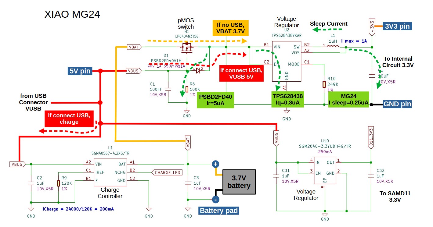
According to my experiments, the LightSleep current was 60.7uA and the DeepSleep current was 1.9uA. The on-board peripherals IMU, MIC, VBAT, RFSW, and Flash are explicitly turned off, and 3.8V is applied to the battery pad.
Possible onboard devices that are not controlled are the step-down converter TPS628438 (0.3uA) and the Schottky diode PSBD2FD40 (5uA). The diodes in particular are greatly affected by temperature and can easily double the leakage current.
For your reference!
‘Light / Deep Sleep Current Comparison of XIAO_MG24 and XIAO_nRF52840’
Thanks for that.
I’ve gone through your (excellent) post and since a standalone 'MG24 should draw <5uA in EM2 (light sleep) wanted to try find if there are any device/s causing additional power consumption (may even be the MG24).
I’ve used the same code and test setup on my own MG24 modules to get the 5uA value.
May have to remove the SAMD11
In my experiment, XIAO is not connected to USB, so SAMD11 is not powered. LightSleep current 60.7uA seems a bit high.
I may need to check how LowPower.sleep(2000) is working for LightSleep.
The current for LightSleep using sleep() is 60uA, and also 60uA when simply delay().
This is a far cry from the 5uA of EM2 LightSleep you got.
Maybe the Sleep() in the XIAO_MG24 BSP is not made with serious consideration of current. Or maybe it was designed to wake up from any trigger source.
hey guys, where can i find the Pin Layout? I only know the Layout form the Wiki site. PIN Layout WIki
In your code here and the turorials there are Pins like PD3 and PD4 and so on. What PINs are these? I try to understand this i’m pretty new in Arduino coding, sorry