I’m not sure there is one - some of the other devices have xlsx files shown on the wiki page…
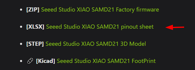
I just use the schematic.
I’m not sure there is one - some of the other devices have xlsx files shown on the wiki page…
I just use the schematic.
Hi everyone,
I’ve conducted some power consumption tests on the XIAO MG24 and wanted to share my results and methodology.
Test Setup:
Optimization Approach:
I focused on systematically disabling all onboard peripherals and putting the flash chip into deep power-down mode. Here’s the complete test code:
#include <Arduino.h>
#include "ArduinoLowPower.h"

#define CS_PIN PA6
#define CLK_PIN PA0
#define MOSI_PIN PB0
#define MISO_PIN PB1

#define READ_DATA 0x03
#define WRITE_ENABLE 0x06
#define PAGE_PROGRAM 0x02
#define SECTOR_ERASE 0x20

void sendSPI(byte data) {
  for (int i = 0; i < 8; i++) {
    digitalWrite(MOSI_PIN, data & 0x80);
    data <<= 1;
    digitalWrite(CLK_PIN, HIGH);
    delayMicroseconds(1);
    digitalWrite(CLK_PIN, LOW);
    delayMicroseconds(1);
  }
}

void writeEnable() {
  digitalWrite(CS_PIN, LOW);
  sendSPI(WRITE_ENABLE);
  digitalWrite(CS_PIN, HIGH);
}

void setup()
{
  //Serial.begin(115200);
  pinMode(PA7, OUTPUT);
  digitalWrite(PA7, LOW);

  pinMode(CS_PIN, OUTPUT);
  pinMode(CLK_PIN, OUTPUT);
  pinMode(MOSI_PIN, OUTPUT);
  pinMode(MISO_PIN, INPUT);

  //SW
  pinMode(PD3, OUTPUT);//VBAT
  pinMode(PB5, OUTPUT);//RF_SW
  pinMode(PD5, OUTPUT);//IMU
  pinMode(PC8, OUTPUT);//MIC
  pinMode(PA6, OUTPUT);//FLASH
  digitalWrite(PD3, LOW); //VBAT
  digitalWrite(PB5, LOW); //RF_SW
  digitalWrite(PD5, LOW); //IMU
  digitalWrite(PC8, LOW); //MIC
  digitalWrite(PA6, HIGH);  //FLASH

  //Serial.println("Deep sleep timed wakeup");
  writeEnable();
  digitalWrite(CS_PIN, LOW);
  sendSPI(0xB9);
  digitalWrite(CS_PIN, HIGH);
}

void loop()
{
  delay(10000);
  digitalWrite(PA7, HIGH);
  delay(500);

  //Serial.printf("Going to deep sleep for 10s at %lu\n", millis());

  // LowPower.idle(600000);        //EM1 TIM wake-up
  // LowPower.sleep(600000);       //EM2 TIM wake-up
  LowPower.deepSleep(600000);   //EM4 TIM wake-up
}
Key Implementation Details:
Results:
Conclusions:
The flash deep power-down command and peripheral shutdown are critical for achieving sub-2µA consumption.
Hello Critic,
Thank you for your test results.
I can’t reduce the current consumption below 100µA by using your code and a XIAO MG24 programmed with Arduino IDE and powered by battery.
I read that EM4 mode is not accessible with the ArduinoLowPower.h library.
Did you use another programming method?
Thank you for your reply.
Bests Regards,
Hi there,
I’m working on that topic too and I’m stuck at 82µA for now in EM2.
Regarding the discussion, there is one thing that I don’t quite understand. @msfujino @grobasoz , from what I read, you’re suspecting some onboard device to be responsible of the leakages that prevent your device to reach 5µm in EM2 mode. But in that case, how can you explain that a consumption as low as 2µA can be obtained in EM4? Except for the onboard buck, switching from EM2 to EM4 should only affects the MCU. Consequently, I was mainly focused on GPIO configurations and looking for badly configured peripheral/clock in my firmware.
By the way, disabling PA08 and PA09, respectively SAMD11_RX and SAMD11_TX, gave me an extra 100µA reduction.
Hi Matthieu_Charbonnier,
Can you post the EM2 and EM4 current waveforms you mentioned?
Sure
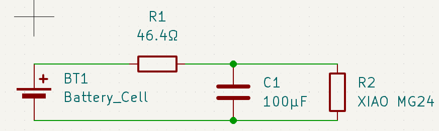
For that measurement I put a 46Ω resistor in series between the battery and the positive input of the XIAO MG24, see the schematic bellow. “Positive input” stands for either Vbat+ or VBus 5V, both gave barely the same results. For that measurement I have physically disconnected the debugger cable from the device.
The device is running an Sleepy End Device Zigbee firmware of my own that I post on gitlab.
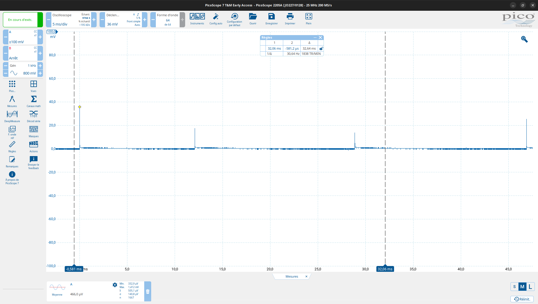
First, see the EM2 behaviour, recorded the average (“Moyenne”, sorry the software is in french) voltage on the resistor 2 full periods, 3.7mV on 46Ω: 80µA.
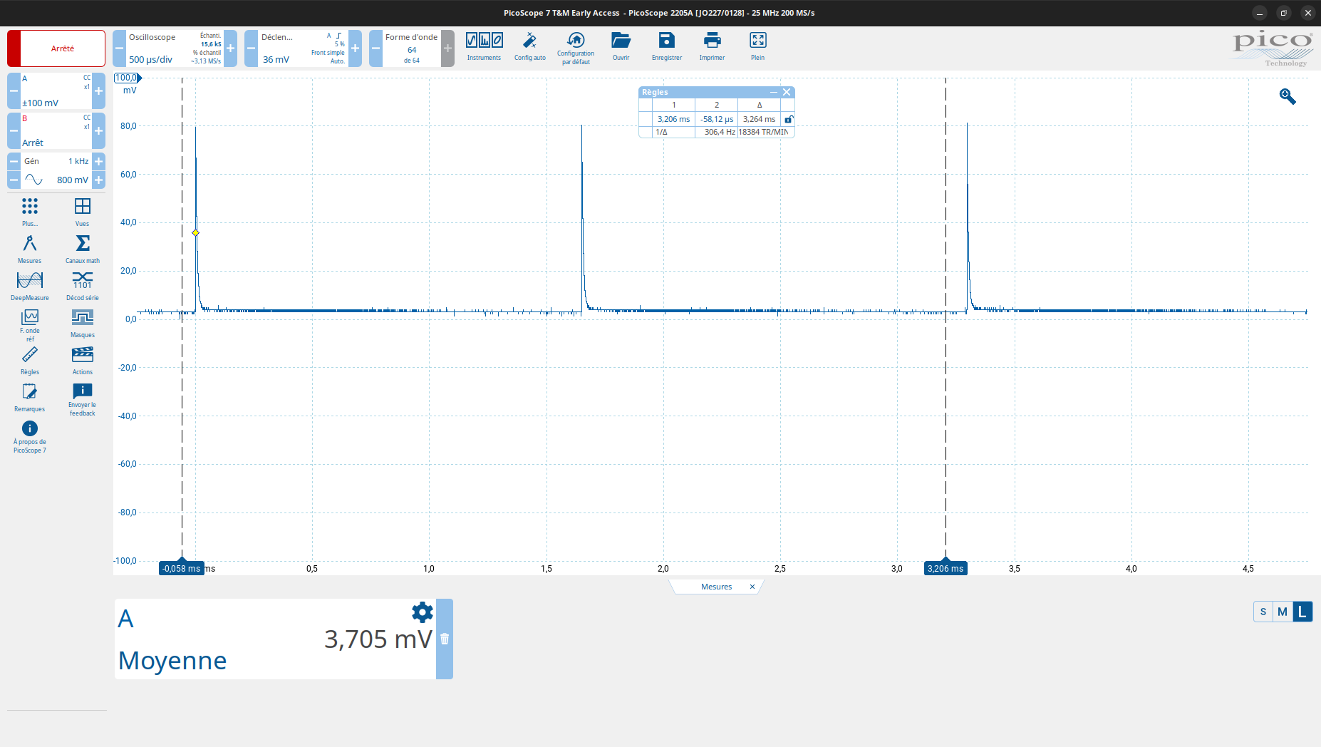
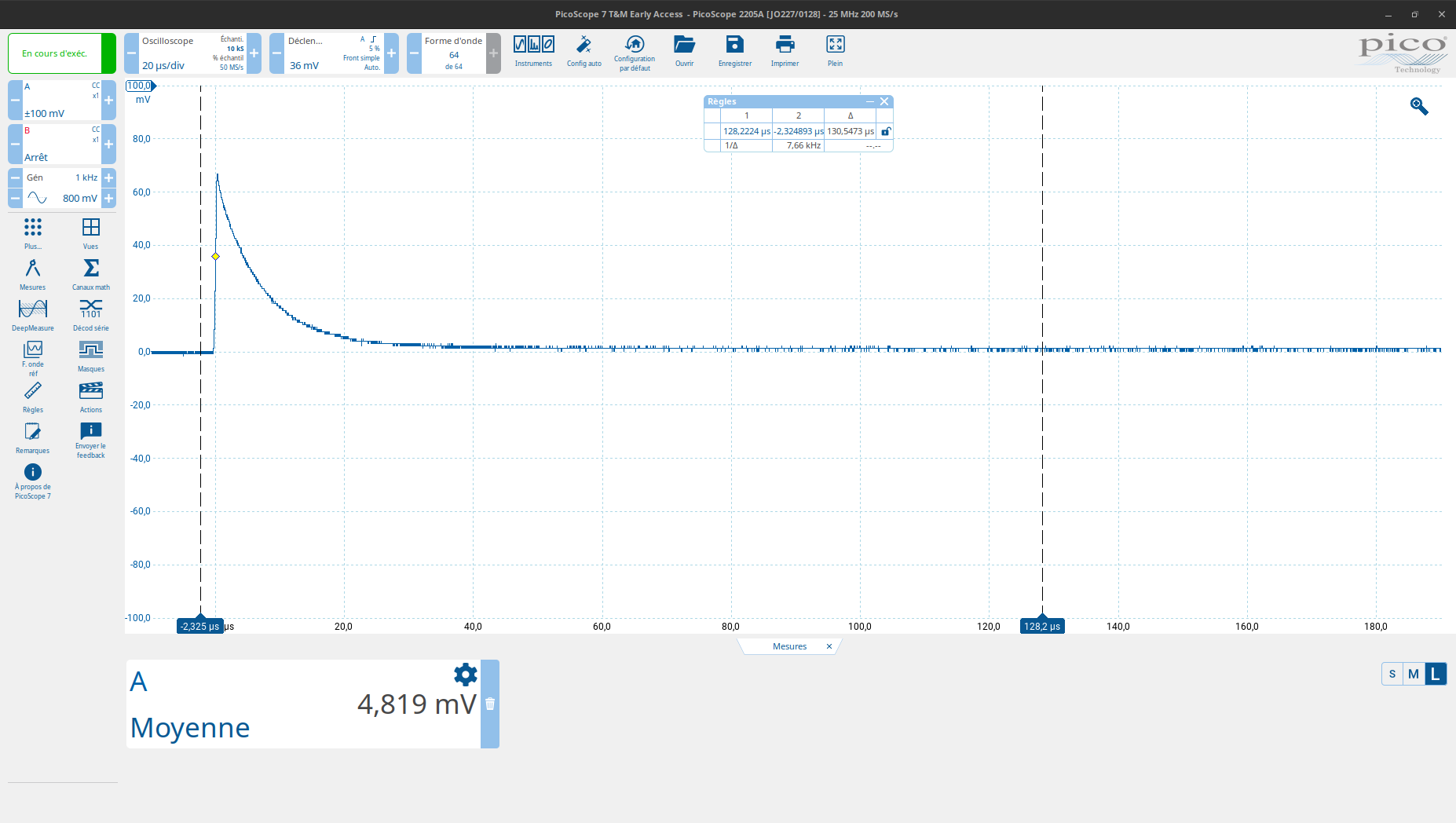
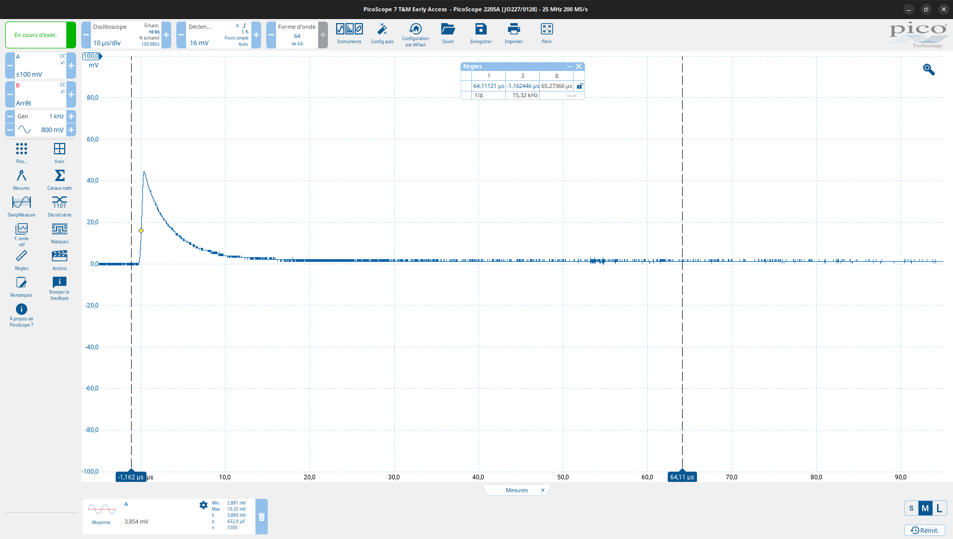
The same firmware is configured to reach EM4 on button press, just for debugging purpose, it’s not in my plan to use it in the … “product”. For a precise measurement I recorded the current pulse and the period separately, see bellow.
From that measurement I conclude that the average current drained in EM4 is 5mV * 128µs / 32000µs * 1/46Ω, 0.4µA. Very very small, but my measurement is probably not so precise, so let’s say, less than 2µA.
So, this make me think that it is really possible to reach the consumption specified in the EFR32MG24 datasheet.
Please refer to Post #13 and the link below.
First, in the case of LightSleep (E2?), a 1mA pulse current flows every 1.28mS, similar to your waveform, and the average sleep current is 60uA. Next, in the case of DeepSleep (E4?), a 1mA peak current flows every 112mS, and the average sleep current is 2uA.
In my opinion, the difference in sleep current is likely due to the varying frequency at which RealTimeOS operates during sleep mode.
‘Light / Deep Sleep Current Comparison of XIAO_MG24 and XIAO_nRF52840’
EM2 / EM4 are from the ERF32MG24 datasheet, Sleep/DeepSleep are misleading because in the datasheet, EM1 is Sleep, EM2 is DeepSleep, EM3 is Stop, EM4 … they didn’t named it, I saw Hibernate somewhere. But here in the forum Sleep is EM2 and DeepSleep EM4.
Anyway, below EM0, the Core is not running. In EM2 the datasheet states that it is possible to run peripheral on the low frequency clocks, such as timers, but still some peripheral may use the HFRCOM23 clock. The consumption observed in EM2 is consistent with HFRCOEM23 still running, though it could be something else of course. But, in my opinion we need to figure out which peripheral is keeping HFRCOEM23 running.
It’s a bare metal project built using Simplicity Studio, I’m not using any RTOS here, as far as I know, unless it is hidden in the Zigbee stack. Moreover, since the core is supposed to sleep in EM2, only timers and peripheral can consume power (And leakage through GPIOs, but I already set up all GPIOs). So, unless they are configured with a high frequency clock (HFRCOEM23), it should only drain a few µA in EM2.
Yes, I got it.
I have the bare metal blinking sample fro Simplicity studio runing at less than 10µA!
It’s just… as simple as disabling SWD pins:
GPIO->DBGROUTEPEN = 0;
Update:
To be more precise, the register is described in the erf32mg24 reference manual page 903. It is GPIO_DBGROUTEPEN bits SWDIOTMSPEN and SWCLKTCKPEN.
The solution also works on the Zigbee Device.