My project focuses on minimizing power consumption during small-capacity data communication between Peripheral and Central. Regarding the current consumption when transmitting data as ManufacturerSpecificData within Advertise packets without establishing a connection, I reported that XIAO_nRF54L15 does not demonstrate overwhelming superiority over XIAO_nRF52840.
“https://forum.seeedstudio.com/t/comparison-of-advertising-current-for-xiao-nrf54l15-nrf52840-and-mg24/294018”
This report compares the current consumption of XIAO board during the most common use case: when Peripheral and Central connect via BLE and exchange small amounts of data. Note that this comparison focuses on the total current consumption of XIAO board, including onboard devices, rather than just the MPU’s current consumption. In the text, each board is referred to as XIAO_52 and XIAO_54L.
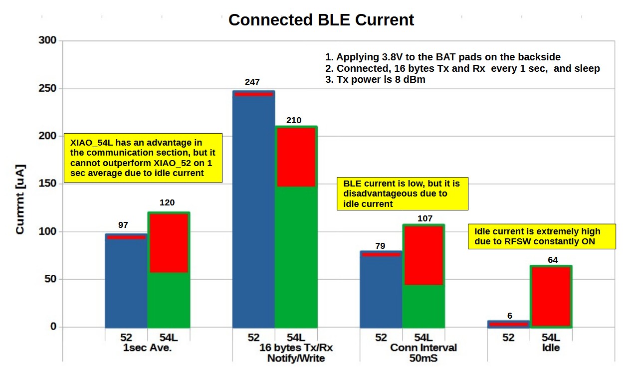
The experiment was conducted using a sequence where the devices transmitted and received 16 bytes of data at 8dBm transmit power once per second, then entered sleep mode. Central used XIAO_54L, while XIAO_54L and XIAO_52, Peripheral’s battery pad was supplied with 3.8V from PPK2 to compare current consumption. XIAO_52 uses an LDO to generate 3.3V, while XIAO_54L uses a buck converter, resulting in significantly different current waveforms. The comparison is based on average current. For the build, Zephyr+ncs was used for XIAO_54L, and the ArduinoIDE was used for XIAO_52.
Onboard device settings:XIAO_54L: The antenna switch is always ON, selecting the onboard antenna; VBAT circuit is only ON when necessary; IMU and PDM are OFF. XIAO_52: The onboard antenna is always used; VBAT circuit is turned ON only when necessary; IMU and PDM are OFF. Flash RAM is OFF.
Based on the experimental results, in my focus project, XIAO_54L:
Requires the antenna switch to be ON to maintain connection, consuming over 60uA of current constantly.
VBAT circuit is only turned ON when needed, but consumes 200uA via the voltage divider resistor, significantly larger than XIAO_52’s 3u.
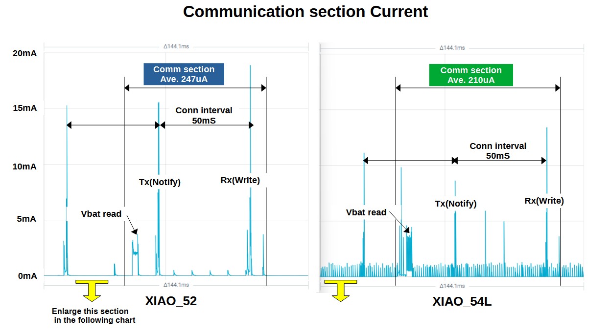
The wireless circuit is efficient and outperforms XIAO_52 when considering only the communication interval.
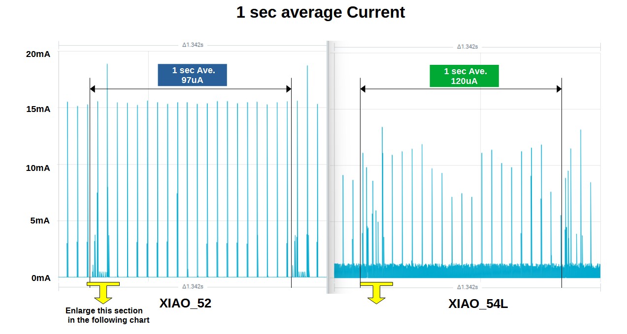
In conclusion, due to the antenna switch current, the average current over one second for XIAO_54L is 120uA, which cannot beat XIAO_52’s 97uA.
Of course, this does not apply to projects where the antenna switch is only powered when needed.
Solid results my Guy.
Not sure if the EXT antenna was worth the Squeeze
same with the Voltage divider. a real PMIC is what’s needed.
(the achilles heal of Xiao) imo for battery devices.
the external Flash delete was a bad move, IMO
I would have prefered a design, closer to an Upgraded Nrf52 Xiao with a Nrf54 core glued in. I’m feeling even on the Nordic end it wasn’t fully cooked. with the LM20 dropping right after, with proper USB and more of the RAM and Flash(rram).
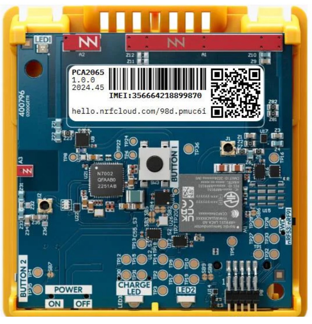
I suspect the chip antenna wasn’t cutting it, the one on the Thingy91x (cellular modem) with the internal nrf54l15 is bigger.
I do in my testing feel like the Nrf54L15 Xiao is connecting faster and in the case of the Central role hears the adverts better indoors. Do you have any S/N data?
you can comment on?
The old pair would never go past office to Lab area(doors, Glass, Metal all of the obstacles, the new set is easily double the distance. I have ordered some additional backup units so more tests forth comming.
I was under the impression that These Xiao’s were more of an Engineering Sample POC to see what was possible. I didn’t expect a Home run at first bat. Add in the Software Dev part, WOW folks don’t want to not have at least a minimal Arduino support. Now I suspect the future there will none for NoOne.
bottom line for me is the nRF54 core is Good.
but the VAR’s implementation can make or break the overall success and acceptance. this device proves it. It appears to me they took away more than they gave on this. Some like the RGB LED was XIAO unique.
I say get back to Basics and look to make sandwich boards for the B2B to get the Options on there. seems like a no brainer Modularity on a low, low level.
For hobbyist in the 2.54mm world, building custom boards is difficult, so I have no choice but to make full use of the XIAO board provided by Seeed. My motivation is to report on the weaknesses and missing features of the XIAO board so they can be addressed in future product designs. Ideally, I’d like to see an improved version like XIAO_nRF54L15X.
As a hobbyist, learning Zephyr+ncs is enjoyable, but the inability to experiment as easily as with Arduino is a major obstacle.
EDIT: The RSSI is about 5 to 10 dBm better on XIAO_nrf54l15.
Thank you both for your love of XIAO and for the detailed testing. This is very important to us—thank you so much!
We hear you loud and clear:
Software: We understand that while Zephyr/NCS unlocks the full power of Nordic chips, the learning curve is a real barrier compared to Arduino. We are actively exploring ways to bridge this gap for hobbyists to make prototyping easier.
Hardware: Your feedback on the “weaknesses” and the idea of a “XIAO_nRF54L15X” is incredibly valuable. We are recording these points to influence our future hardware definitions.
Performance: It’s encouraging to see the RSSI showing a 5-10 dBm improvement in your tests!
Please keep the feedback coming—it directly helps us build better tools for Makers.
In this report, to compare with XIAO_52, XIAO_54L also selected the onboard antenna via the antenna switch. To maintain BLE connection, the antenna switch consumes 60μA of current.
If the external antenna is selected, 140μA is consumed, resulting in a significant disadvantage.
Hi, have you tried not to use the buck converter of the XIAOI_54L and compare the figures with the XIAO_52 ? If possible, it will give you intrinsic performances of both siliciums.
So, I’m kinda perplexed Why wouldn’t you look at the Nrf52 design and Know the next one should meet or exceed the specifications for low power and Battery use.
They should use the Best case Test Scenario for Xiao Nrf52840 BLE
" Those values should be the BASE-LINE.. Period ". No new design should have WORSE numbers than that , Instead it’s WAY worse..
I brought the Technical info to the forefront on here the Specifications for the Silicon.
How they manage to snatch defeat from the jaws of Victory baffles me.
I thought it would be the addition of the Samd11 for the SWD and USB port would be an issue (it’s not).
Well I guess , It’s all on SANTA Now. He needs to bring us a nice new xmas present and it should have an RGB LED Please Lord!
FIX : iMo , LOSE the External Antenna & Switch… PUT the RGB LED back and the External Flash. (I’m not a fan of the Voltage divider, (NOTE 1)).
Now we have the New and IMPROVED - Nrf54L15X Xiao.
Seasons Greetings
GL PJ
Note:1
The battery read voltage divider, is a Bandaid not a fix, Users deserve a PMIC , heck even a MAX chip in (reTerminal) on a daughter card like the Logger or through a B2B connector option on the bottom. Stacking is the future for XIAO IMO.
I would like to see the Seeed engineers investigate using a UFL connector with a “passthrough” option (eg MM8130 from Murata). No need for an active semiconductor RF switch. The price may be an obstacle but the benefits would be huge.
So, I get what you mean no need for the Active part, However
NoT that part…
it’s basically “internal antenna until someone physically jacks in coax.” Great for lab work and factory testing, not so great as a default RF architecture for every user.
" The MM8130 (and similar) are “antenna test / connector switches” that let you:
Use the on-board antenna in normal operation
But when you plug in a test cable, a mechanical RF path diverts to the coax port for measurement "
They’re mostly meant for:
RF test points during development & production
Temporary connection to a VNA / spectrum analyzer / test receiver
NOT as a general-purpose external-antenna port for end-users in the field
They have their place… just not here.
they are NOT good for Battery-oriented nRF54L15 Xiao
“passthrough” U.FL switching connector:
Adds series and shunt parasitics in the antenna path
Degrades matching if not absolutely perfectly designed
Costs you link budget (in both TX and RX)
Makes it harder to achieve a tight band-limited match on a tiny onboard antenna
For a low-power SoC like nRF54L15, you fight for every dB.
Throwing in an RF “test switch” in the main path for every customer is the opposite of what you want. (this external switch we have is this nightmare)
If you really want dual-antenna or selectable antenna behavior, a proper RF switch (like the one used in Nordic’s ref designs for external antenna options) gives you:
Predictable insertion loss
Known isolation
Clean control (GPIO or bias) Fumble IMO
The ability to power it down or choose the optimal path
The MM8130-style part is a production test / bring-up convenience, not an RF architecture.
The XIAO nRF54L15 is aimed at:
Very low power IoT
Tight PCB real estate
Makers who often never touch RF layout and just want it to work like me & you.
Best choice for that world:
One really good on-board chip antenna, well matched
Possibly a second variant SKU with U.FL for external antenna if they want to serve enclosure / high-gain use cases
Maybe a pro version (bigger board) with RF switch and selectable onboard/external paths
Putting a “test passthrough connector” into this adds:
Cost (you guessed it BIG time)
Loss
Layout complexity
Board space
More ways for users to mis-use it
And doesn’t actually make life easier for Seeed or normal users. For a tiny XIAO-class board, a single, high-quality chip antenna is often better than a compromised dual-path kludge we got currently.
I’ve had a chance to read through all the information you supplied above and had a revisit some of the Murata tech docs.
Cost - the current UFL + RF Switch combo is about the same price as a MM8130.
Application - while primarily for testing, the MM8130 (and other smaller connectors MM8030 etc) can be used in commercial devices with a suitable antenna/connector.
Insertion loss - the RF switch on the current XIAO NRF54L15 has a higher insertion loss than the MM8130.
The NRF54L15 DK has an MM8130 installed so I can grab an antenna and do some testing at a later stage. NB. Standard XIAO UFL antenna won’t work.
From a supplier and production point of view, having two devices, one for each of UFL/Chip antenna can be more difficult, logistically, and more costly than having a single solution.
From a user and developer’s perspective, I prefer the single product, dual antenna approach. I can purchase higher volumes of a single device and configure accordingly.
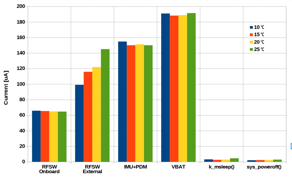
I measured the current consumption of the onboard devices of XIAO_nRF54L at room temperatures ranging from 10°C to 25°C. With the exception of RFSW (External antenna), the values remained nearly constant. The issue arises when RFSW is set to ‘External antenna’, as it consumes a current that exceeds the values stated in the datasheet. Furthermore, it exhibits extremely high temperature dependency. When housed in a case or used outdoors, the current consumption could potentially exceed expectations. In any case, this combination seems unsuitable for the energy-efficient nRF54L15.
Perhaps it would be good for you to check first… Its a testing part NOT production.
Period!
External antenna defeats the Low power Goal.
I don’t think YOU have ever used one, seriously AI or NOT, It sounds GREAT!
I have in radar testing.. IF Chassis, If you don’t plug it in just right it’s broken easily, anyone with experience will tell you it’s for testing NOT for production.
Users have enough trouble installing the standard Xiao antennas, look at the number of posts to that effect.
not for production bro…look again you would have to buy Tape&Reel and Mass quantity , you see the lead times too? " C’mon man…" ESPN
"
Dear Santa Seeed Please Give US an XIAO Nrf54L15 LP (Low Power) for Christmas I don’t even care if it’s a
**re-Gift! ** Remove the External ant connector and switch, adjust (raise, increase) the resistor values for the Battery reading Voltage divider so they fit the LowPower profile. The new SKU # will save you money and increase sales.
" Xiao nRF54L15 LP "
IMO it’s the easiest solution to get all the way there. a couple DNP’s (Do Not Populate) and 2 resistor value change is a NO brainer. The feedback is IN.