My idea for implementing the two antennas is to use small solder pads instead of an RFSW and switch them using solder bridges. However, I’m unsure how much the pads and solder bridges will affect impedance matching.
1 Like
Hi msfujino,
your graph pretty much sums up the power consumption I see on my board,
thanks for the nice overview!
Did you make any effort tracking down the power consumption of the IMU/PDM any further?
With IMU power enabled and the PDM turned off I also get 150uA power consumption, with power peaks occuring at 2.5kHz.
According to the datasheet, the IMU itself should only be consuming few uAmps itself in powerdown mode, any Idea where the power is lost here?
My suspicion is that the CS Pin of the IMU leaks, as it is continously driven via 3V3 when enabled, but as of now I do not see a good possibility to confirm…
BR
Lukas
Hi lahn,
- I believe it’s being measured with ppk2, but what voltage is being applied where? I’m applying 3.8V to the battery pad.
- When IMU&MIC3V3 is enabled, the current consumption becomes 150uA, but I’m not sure if Zephyr is initializing the IMU and MIC. Try explicitly putting the device to sleep to clarify.
- Generally, input currents on pins like CS are typically only a few uA at most.
- You mention a 2.5 kHz peak, but if you measure the current at the battery pad, it might simply be the switching effect of the regulator.
- If you could post the measurement data, we might be able to figure something out.
Hi,
-
I’m also measuring with PKK2 at 3.7V connected to the battery pins.
-
I explicitly set the XL and Gyro to power down mode (odr set to 0 at CTRL1_XL and CTRL2_G) and I do see the expected increase in current to ~160µA when setting XL to 12.5Hz, indicating the running accelerometer.
-
This is my understanding as well, although I do not have a single LSM6DS3TR lying around to check…
-
That may also be, also there seems to be a problem with the buck converter, which I also see in my measurements when I go near/below 3.5: xiao-nrf54l15-with-a-coin-battery
I assumed that to be a problem only for specific power ranges?
As I have not setup any component running near 2.5kHz it indeed has to be some internal switching freuqency of either the IMU, the PDM or the Buck converter
- Here is the measurement in detail, with the 2.5kHz peaks visible. The IMU is in sleep mode, which produces the expected peaks at 12.5Hz as seen below as the areas more dense.
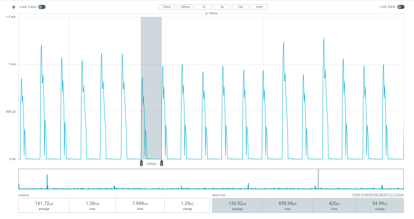
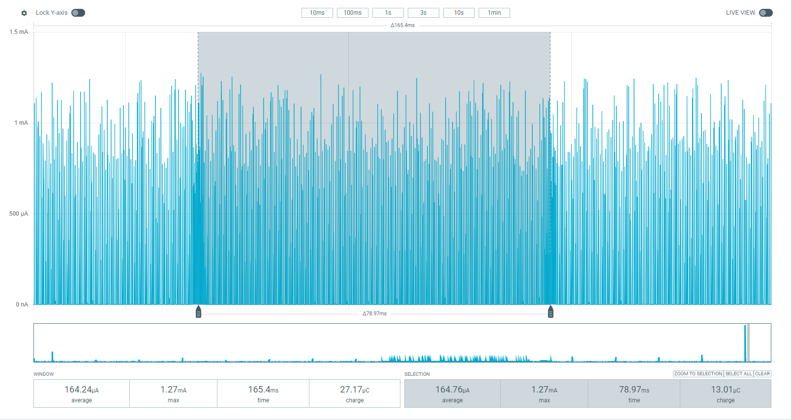
The peak visible around 2.5 kHz is likely due to the buck converter operating in Pulse Frequency Modulation mode under low load conditions. The frequency should vary with the load current.
1 Like
As I haven’t seen anyone mention it , I will:
When exactly 3.3V is applied at the battery pads of nRF54L15, power consumption grows quite a lot, decreasing back at 3.2V. This is due to the voltage regulator. but very bad for battery projects, where voltage can go a lot lower.
A LDO with small power consumption would probably be better, same like the nRF52840 would probably work better.
The voltage doesn’t have to be held at 3.3V. Most of the time, I keep my board under-volted , and power consumption drops significantly.
And powering from a 3V coin-cell battery works for a longer time!
1 Like
Here’s an update. I’ve posted the results of my BLE current evaluation using ArduinoCore below. Please take a look if you’re interested.
1 Like