The XIAO nRF54L15/LM20A features a USB-to-nRF54L bridge based on the SAMD11. If, for any reason, the firmware on the SAMD11 becomes corrupted, the COM port will disappear, and the board may become “bricked”. We can restore the board to its factory-default state using the SWDIO2/SWCLK2 pads on the back of the board. I created a rescue tool that uses an inexpensive STLink (clone) or DAPLink (built using a XIAO SAMD21) as the debugger, together with OpenOCD, which is included in the Seeeduino board support package.
As described in the datasheet, the SAMD11 has a feature called BOOTPROT that protects the flash memory from being overwritten, preventing unintended firmware overwrites. Unfortunately, this protection feature is not enabled by default. With this rescue tool, we can enable the protection feature after flashing the firmware by running flash_prot.bat.
The factory-default firmware may be available from Seeed, but the attached file was downloaded directly from my SAMD11 using backup.bat.
If you plan to build a DAPLink, please refer to the instructions in the appendix.
SAMD11_RescueTool.zip (635.5 KB)
Flashing Firmware to the SAMD11
1.1 Open the folder corresponding to the debugger and XIAO nRF54L target you are using. SAMD11_L15_DAPLink, SAMD11_L15_STLink, SAMD11_LM20A_DAPLink, SAMD11_LM20A_STLink
1.2 Open the appropriate .bat file in a text editor, modify the PATH settings to match your environment, and save the file.
backup.bat : backs up the target’s firmware.
flash_prot.bat : flashes the firmware and enables flash protection.
flash_unprot.bat : flashes the firmware without enabling flash protection.
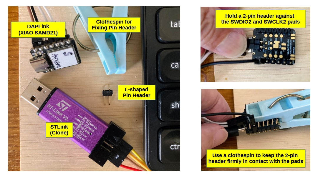
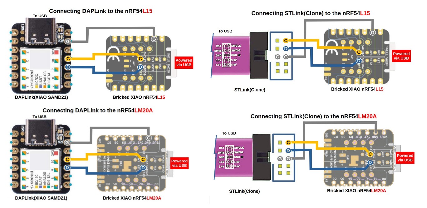
1.3 Connect the debugger to the target as shown in the connection diagram in the connection folder. Soldering the connection is the most reliable method. Alternatively, you can place a two-pin header on the SWDIO2 and SWCLK2 pads and secure it with a clothespin. This method works well for short-term use.
1.4 Be sure to power the target via USB.
1.5 Connect the debugger to the PC.
1.6 Double-click the appropriate .bat file to execute it.
Appendix
Build a DAPLink (Windows 10)
2.1 Open the DAPLINK folder.
2.2 Connect the XIAO_SAMD21, which will be used as the debugger, to the PC.
2.3 Quickly reset twice to enter bootloader mode. The orange LED will flash slowly, and an Arduino drive will appear on the PC.
2.4 Drag and drop the simple_daplink_xiao.uf2 file onto the Arduino drive. Once the UF2 file has been successfully uploaded and DAPLink is established, two blue LEDs will light up.
Build a DAPLink (Windows 11)
3.1 Open the DAPLINK folder.
3.2 Right-click the Start icon on your PC and open Device Manager.
3.3 Connect the XIAO_SAMD21, which will be used as the debugger, to your PC. Note the COM port number of the USB serial device that appears in the Ports list (for example, COM9).
3.4 Quickly reset twice to enter bootloader mode. The orange LED will slowly change color, and an Arduino drive will appear on the PC. Note the COM port number of the USB serial device that appears in the Ports list (for example, COM10).
3.5 Reset the device and confirm that it has returned to the original COM port number.
3.6 Open bossac_flash.bat in a text editor and modify the NORMAL_PORT and BOOT_PORT values on lines 3 and 4. For example:NORMAL_PORT=COM9 , BOOT_PORT=COM10
3.7 Similarly, modify the PATH settings to match your environment on line 11 and save the file.
3.8 Double-click bossac_flash.bat. If the upload is successful and a DAPLink connection is established, two blue LEDs will light up.
I referred to the link below
’ Build a DAPLink Deivce using Seeed Studio XIAO SAMD21 | Seeed Studio Wiki
’ Use Arduino Borads as DAPLink Device | Seeed Studio Wiki
’ How to unbrick a dead XIAO using a XIAO(DAPLink) and OpenOCD
’ How to unbrick a dead XIAO using ST-LINK and OpenOCD