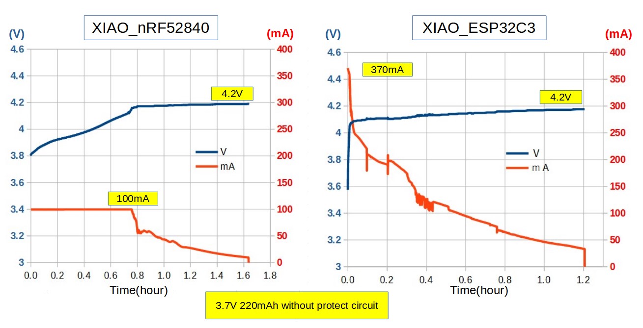
XIAO_nRF52840 and XIAO_ESP32C3 have a built-in charging function, but since the circuit diagram was not disclosed, I assumed that they have the same circuit. I was curious and measured the charging characteristics. They are completely different, XIAO_nRF52840’s charging current can be set to 50mA or 100mA by firmware, but XIAO_ESP32C3’s is fixed and very large at 370mA, so I need to be very careful when using small capacity batteries.
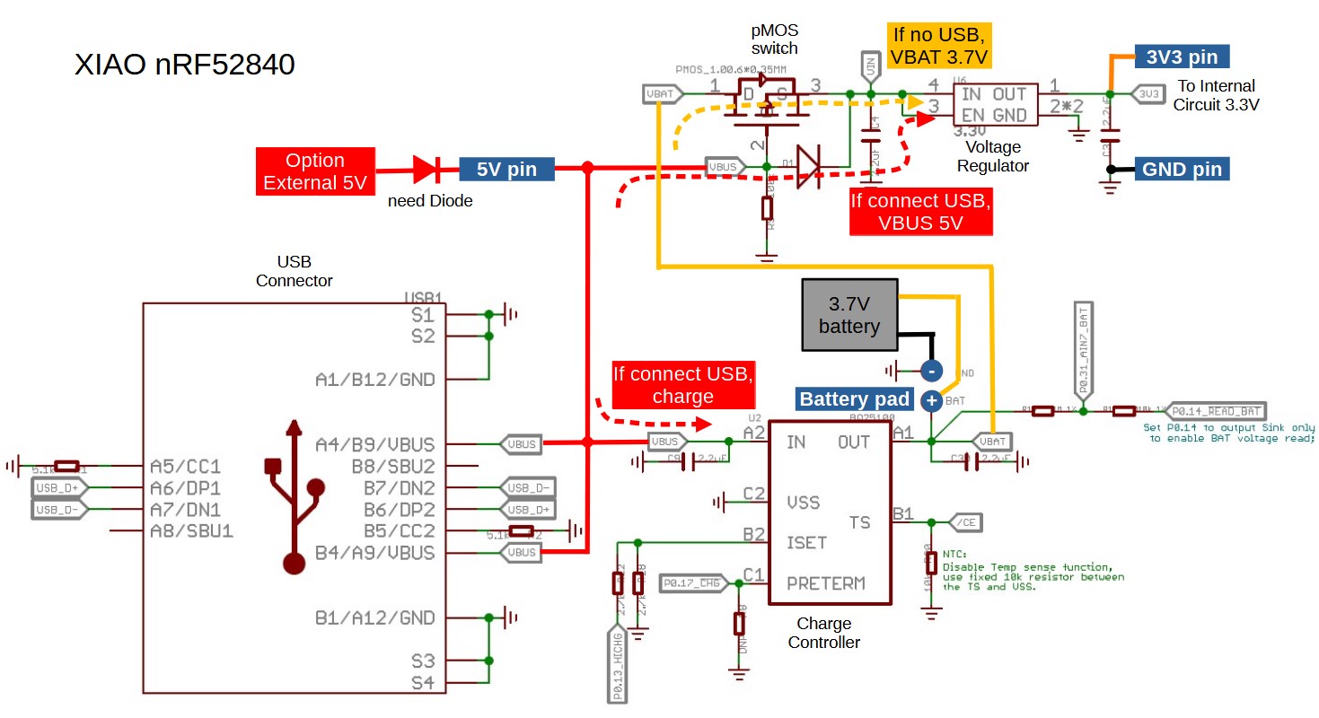
I have extracted the power and charging circuit parts from the published schematic.
I hope this will be helpful when troubleshooting.

Thank you, that is interesting. For XIAO ESP32C, the U1 battery charger chip is assumed to be Torex XC6802A42XMR-G XC6802A42XMR-G Torex Semicon | C160463 - LCSC Electronics
The datasheet is here: Microsoft Word - XC6802_ETR2501_009.doc (lcsc.com)
Regarding charge current, here is how it is set:
The charge current can be set by connecting a resistor between the ISEN pin and the VSS pin. The battery charge current, IBAT,
is 1000 times the current out of the ISEN pin. Therefore, the charge current, IBAT, is calculated by the following equations:
IBAT = (VISEN / RSEN) x 1000 (VISEN = 1.0V (TYP.): Current sense pin voltage)
Therefore, 1 / 2700*1000 = 0.37A or 370mA maximum charge current.
To protect the battery, we can see that ESP32C3 should not be used with batteries less than 370mAh unless the battery has an external protection circuit that takes care of over-current charging.
Your suggestions are all excellent!
Request to the Seeed Studio team :
- Is it possible to update the ESP32-C3 module schematic by adding the chip model for U1 (LiPo Battery charge chip) ?
- Is it possible to update the Wiki “Battery Usage section” by adding the charge current of the built-in chip and the recommanded LiPo batteries (min/max capacity) ?
Regards
Thanks @msfujino for this detailed schematic.
Reading it, I’ve understood that one could connect 3V3 external power supply directly to 3V3 pin et GND pin.
I’ve tried this but it doesn’t work.
Is there a way to achieve this?
I have missed something?
I’m talking about XIAO ESP32C3.
Hi n47h4n,
I’ve tried this but it doesn’t work.
Please be specific.
Is USB or battery connected?
How many volts are on the 3V3 pin?
Neither battery, nor usb are connected.
Only an external 3V3 power supply.
I was sure it would be sufficient, but the test blink app does nothing.
If USB is connected alone, the app works fine.
Edit: there are 3.5V exactly
Why don’t you try setting the external voltage to 3.3V.
I’ve just tried it.
It was easy as it’s an ajustable power supply.
3.3V exactly, but it doesn’t work better.
Current is sufficient. I use a LM317T. It can go up to 2.2A
There must be a protection somewhere…
As new user I can’t reply more than 3 times.
So I edit this one hopping it will be seen.
Oh yes, I know.
My test app uses an external LED on GPIO10.
To be sure, I’m going to upload an app that writes to serial, and connect an UART adapter on RX and TX, and see what happens.
Bingo!
You are the best!
After removing while(!Serial); it works fine.
So it’s not a power issue.
And the XIAO can work with external 3V3…
Thanks for your help and the time you spent.
Just to let you know:
- Serial.print goes to USB, nothing is visible on RX and TX
- upload is not possible using esptool + TX/RX. Only esp-builtin via USB is possible
But that’s not a problem for me.
XIAO ESP32C3 has no user LED. When connected USB, charge indicator is blinking.
If you can show me your “stuck” sketch, I can try it out on my XIAO.
I have a feeling that Serial.print() has something to do with it. Is there “while(!Serial);”.
This thread reminded me (because it says so, nonchalantly, on the webpage about the seeed xiao esp32c3 board) that the on-board LED is not a power indicator. It is only telling you that it’s trying to charge a battery. If no battery connected, it freaks out and blinks fast. If a battery is connected and needs charging, it will be solid. When the battery is full, the LED is dark. One other behavior I noticed is if the battery is connected backwards, the LED will blink. The blinking speed changes over time and eventually becomes solid.
Hi there,
Yea, they mark it under "it’s not a bug it’s a feature " ![]()
![]()
C3 is on it’s own, must have been created between the shift change at Espressif ..
SPi, Memory, wifi, there is a whole lot different than the rest of the Fam for sure.
I think the C5 is the better of ALL them. IMO.
HTH
GL ![]() PJ
PJ ![]()