I’ve built a weather station using a Grove BME280, and Grove base with ESP32C6. I need it to run in lower power mode so that a battery can power it for several weeks or months on a single charge. I read (and found out the hard way!) that the Grove BME280 board can draw significant current even when the chip itself and the ESP32 are in deep sleep mode. I also read that the way to fix this is to power the BME280 from a GPIO pin and turn it on only when the station periodically wakes up to broadcast readings using BLE. I prized the GND and 3.3V lines from the Grove cable on the I2C for the BME280 and connected them to another Grove plug which goes into GPIO 0.
The problem I’m having is that the BME280 gives quite different readings when powered from GPIO. (humidity reading doubles, pressure reading down by ~30%). The software, including BLE and deep sleep mode, all works perfectly. The problem goes away if I revert to the original cabling so it’s definitely an issue with the GPIO power. I had two thoughts:
The BME280 needs time to stabilize after power on. I’ve tried values up to 5ms but it makes no difference
The combination if I2C comms but power from GPIO has some gotchas that I’m not aware of and can’t find any online references to
Does anyone have any ideas or experience with this setup that might help?
The BME280 has a mode that stays asleep until triggered, so it should keep power consumption low even without turning off the power supply. The link below shows a similar approach, so it might be helpful.
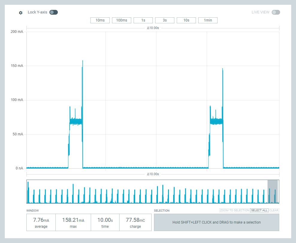
Thanks for the reply. Yes, the BME280 chip has a sleep mode but the Grove board itself continues to draw power. My sketch wakes up for 30ms every 5 seconds so that’s just 0.6% of the time. It’s draining a 1100mAh battery in ~100 hours so that’s 11mA average consumption. I read that it’s not the BME280 chip itself but the Grove board circuitry that is the problem, so some sort of explicit on/off power management is needed. I did that quite easily, but I can’t figure out why the BME280 gives such different readings depending on the power source.
The BME280 board is here: Grove - Barometer Sensor(BME280) | Seeed Studio Wiki
It’s supposed to work on 3.3V, which is what the GPIO should give. The whole station also works fine on 3.7V LiPo rather than USB power, The wiki says operating current is 0.4mA but I’m seeing far higher than that.
Again, everything works 100% OK with just I2C cabling except that power drain is unexpectedly high. The principal issue seems to be figuring out why the sensor readings are different on GPIO power.
I suppose it is just possible that the Grove shield itself draws current even when the ESP32 is in deep sleep, but I can’t find anything on this one way or the other.
Per Pin Limit: The maximum recommended continuous current draw for a single GPIO pin is typically around 20mA, though the absolute maximum can be up to 40mA depending on the specific chip and software configuration.
However, in your specific scenario, the current limit is unlikely to be the root cause of the wildly inaccurate readings, but rather a factor in how power is delivered and stabilized
Try increasing the delay after applying power to the GPIO pin to 100ms or 200ms before initializing the I2C bus or sending any commands. This is a common requirement for complex sensors like the BME280.
for those following along,
The BME280 sensor itself is extremely low power:
Sleep Mode: As low as 0.1µA (microampere).
Active Measurement: It typically consumes less than 1mA (milliampere, or 1000µA) during measurement and communication.
AI ,
Added this ;
The problem you are experiencing is likely due to the quality of the power signal and the startup sequence, not the maximum available current:
Inrush Current/Capacitor Charging: When you first switch the GPIO pin HIGH, the sensor’s onboard decoupling capacitors need to charge instantly. This creates a very brief inrush current pulse that can be much higher than the average operating current (potentially 100mA or more for a moment).
Voltage Sag: The GPIO pin might experience a momentary voltage sag during this inrush, preventing the sensor’s internal circuitry from starting up correctly or causing its internal power-on-reset sequence to fail.
I2C State Issues: As previously mentioned, the “back-powering” issue through the SDA/SCL lines is a major source of erratic behavior when the VCC pin is switched off but the I2C lines are not properly managed.
To fix your reading issues, focus on the software sequence and potentially adding a small decoupling capacitor as suggested in the previous response, as the current limit of the pin itself is sufficient for the BME280.
HTH
GL PJ
BTW, The standard Grove BME280 breakout board might draw slightly more (around 0.4mA to 0.6mA typically, according to Seeed Studio specs) because of onboard components like pull-up resistors and, sometimes, an LED indicator.
I’ve tried delays up to 500ms but the problem persists. It also looks like the incorrect readings are fixed and don’t change, which suggests that the sensor readings are silently failing. I’ve checked that the values are not simply from uninitialized variables in my code so they must be coming from within the BME280 library itself. (This library is the Grove library(“Grove - Barometer Sensor BME280”, v 1.0.2 by Seeed) . There are no errors returned from the init() call and no exceptions thrown by the sensor reading methods.
I also tried initializing the BLE modem before initialising the BME280 but, again, the problem is still there.
Again, if I revert to just I2C cabling everything works fine but that leaves me with the power drain problem.
The AI response you posted mentions the decoupling capacitor but I don’t see any details in the text.
If I might add…. I think MS is saying it takes a little time for the sensor to warm up to the correct reading, so you man need to give it that time, similar to a GPS unit, you cant just turn it on for a second and expect the readings to be correct maybe you write the code to power longer period for startup, or analyze until the readings stabilize
Can you post a photo of your wire… the ground in the grove connector can remain
You could connect directly to the 3v3 and ground Data-A and Data-B or you could connect 4 GPIO and bring one up and one down… that reminds me pull up resistors enabled in logic, could be a problem
The female can press right into the XIAO pins
also the product data page says it can be 5v or 3v3… so i dont know if it has an onboard power regulator… or if it can tolerate both
Hardware Overview
SPI soldering pads, a voltage monitoring circuit.
I guess those three transistors are the level shifters
you should be able to probe the pads at the spi to check voltage, also the capacitor could go between power and ground here
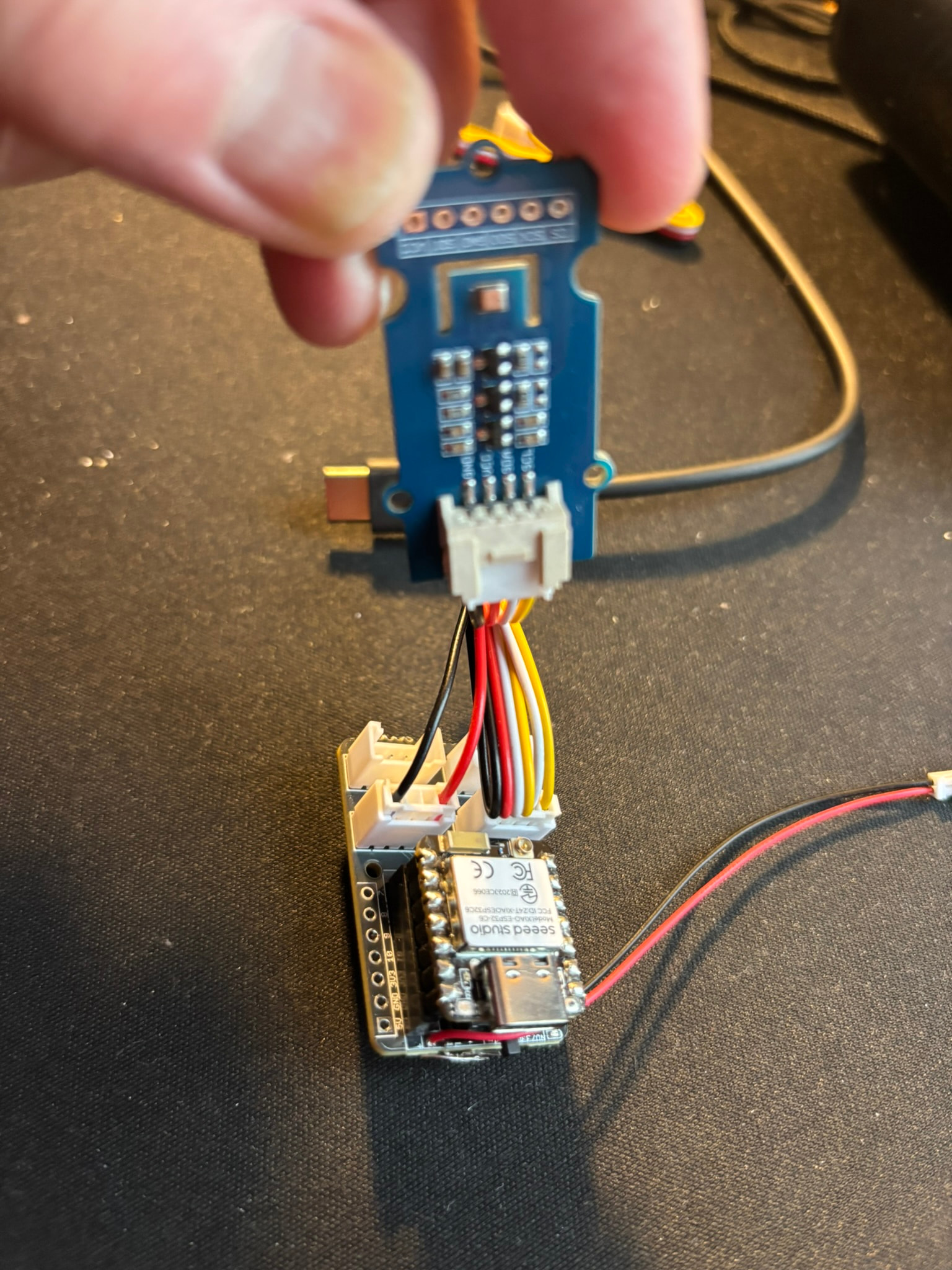
So here’s a photo of the device including wiring. It’s a bastardized Grove cable: the SDA and SCL connectors on the I2C are left in place. The GND is connected to GND on the first GPIO connector and VCC to GPIO 0. (Leaving GND connected to the GND on the I2C makes no difference.) I’ve checked connectivity and the hacked cable is OK. My meter is pretty basic so I can confirm that the GPIO pin does reach ~3V and give 47.5 mA with just C6, but trying to measure current with BME280 is hopeless
Thanks. I’m not entirely convinced that the problem is due to settling in after power-up. On just I2C connection, the device works instantly and correctly, by which I mean it gives same readings as an indoor, USB-powered version of the same device. I’m guessing there is some complexity in cabling power and data from two different places.
P.S. I’ve also dived into the Seeed BME280 library and the init() call won’t proceed unless it successfully detects the chip via chip ID register, and retries 5 times at 100ms intervals if it can’t. The data readings use the same code as that for reading the chipID register, so I can’t see why one would work while one fails. Again, I have to emphasise that everything works 100%OK on just vanilla I2C cabling.
why does it look like you have double wires going to everything?
also can you be clear what you mean by failing
If I remember correctly you initially said the sensor value returned was incorrect
I see you said 30% error but can you give exact examples
Why do you need to sample data so frequently… for a weather station once every 5 minutes would be more than adiquate
With IIC communication you are reading regesters. so for the data to be corrupt the regester has to be corrupt… its not like you are interpolating a analog signal
the only way the regester read could be corrupted on the recieving side is some type of bit rounding
this is why i am saying the regester corruption has to be happening on the sensor side, and as you have stated, the only change is the power and ground setup.
So you are using D0 as your power pin
I like your red and black 2 wire on one grove… on the other I would say do either 2 wire only white and yellow or three wire, Black, white and yellow
The double wires is just an illusion because the Grove connector wire is folded over. The wiring is simple: the data wires (white and yellow) go from the I2C connector on the Grove shield to the SDA and SCL connectors on the BME280. The GND and 3.3V from the GPIO connector on the Grove shield go to GND and VCC on the BME280 respectively. Basically, I prized the red and black wires from one end of a Grove connector and inserted them into another Grove connector so that I could connect to GPIO. I did originally try with GND remaining also on the I2C connector, i.e just moving the red wire to a separate connector, but it made no difference. Yes, it’s GPIO D0. My primitive meter does show power coming on every 5 secs as expected.
By failing, I mean that it reports incorrect values for temperature, pressure and humidity.. Here is what I see with the device connected by straight I2C:
These value are in agreement, to within device accuracy, to both a USB-powered device and an old Oregon Scientific weather station sitting about 20cm away.
(ignore the ID Xffff line as that’s just a minor cosmetic bug)
Here is what happens if I use the split I2C/GPIO cabling:
I got ya… what the picture is showing is totally not that, so can you show a
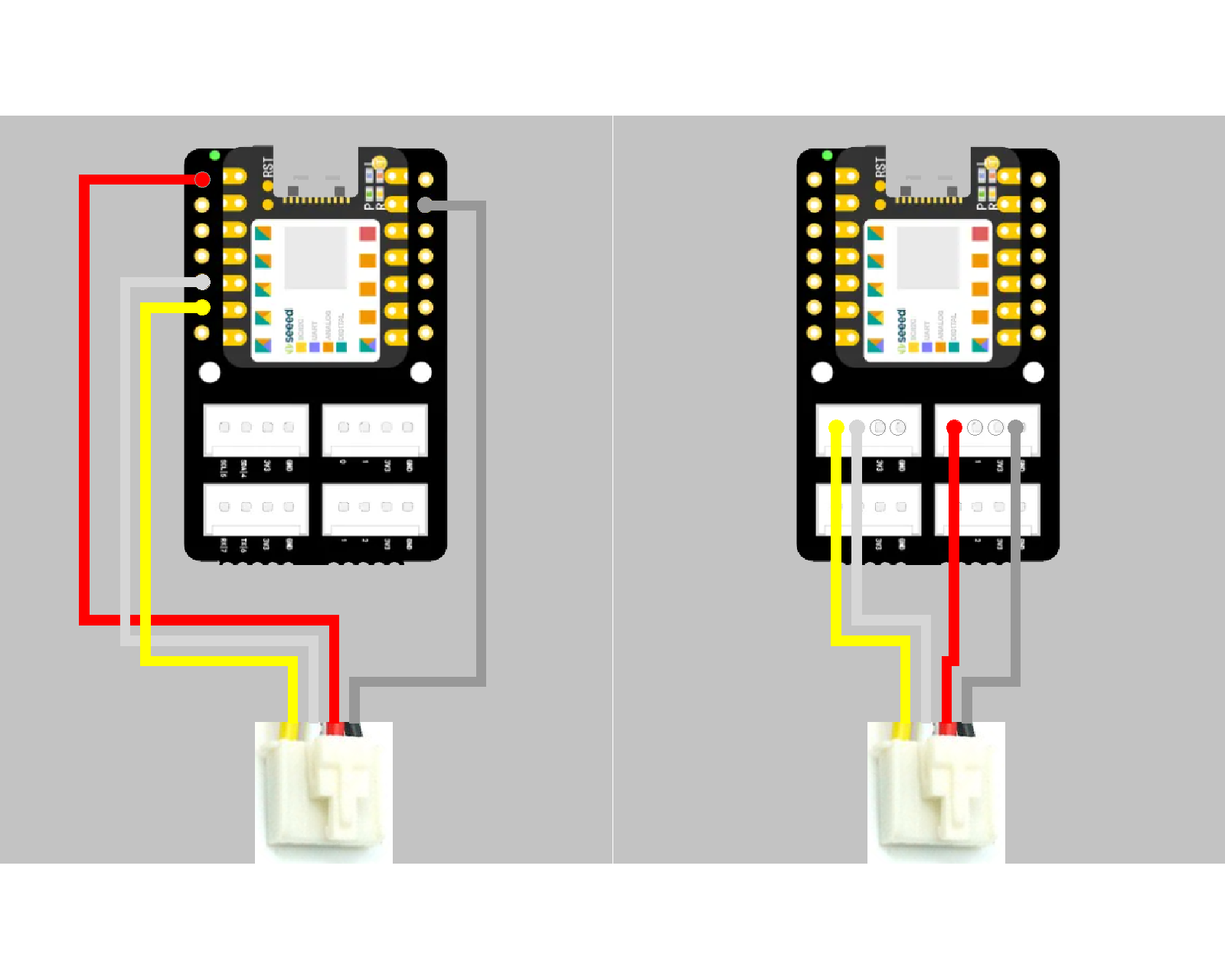
picture with only 4 wires… black and red from the #0 Grove Port and Yellow and White from the #5 Grove Port. Thats what you would be looking for, as far as setup