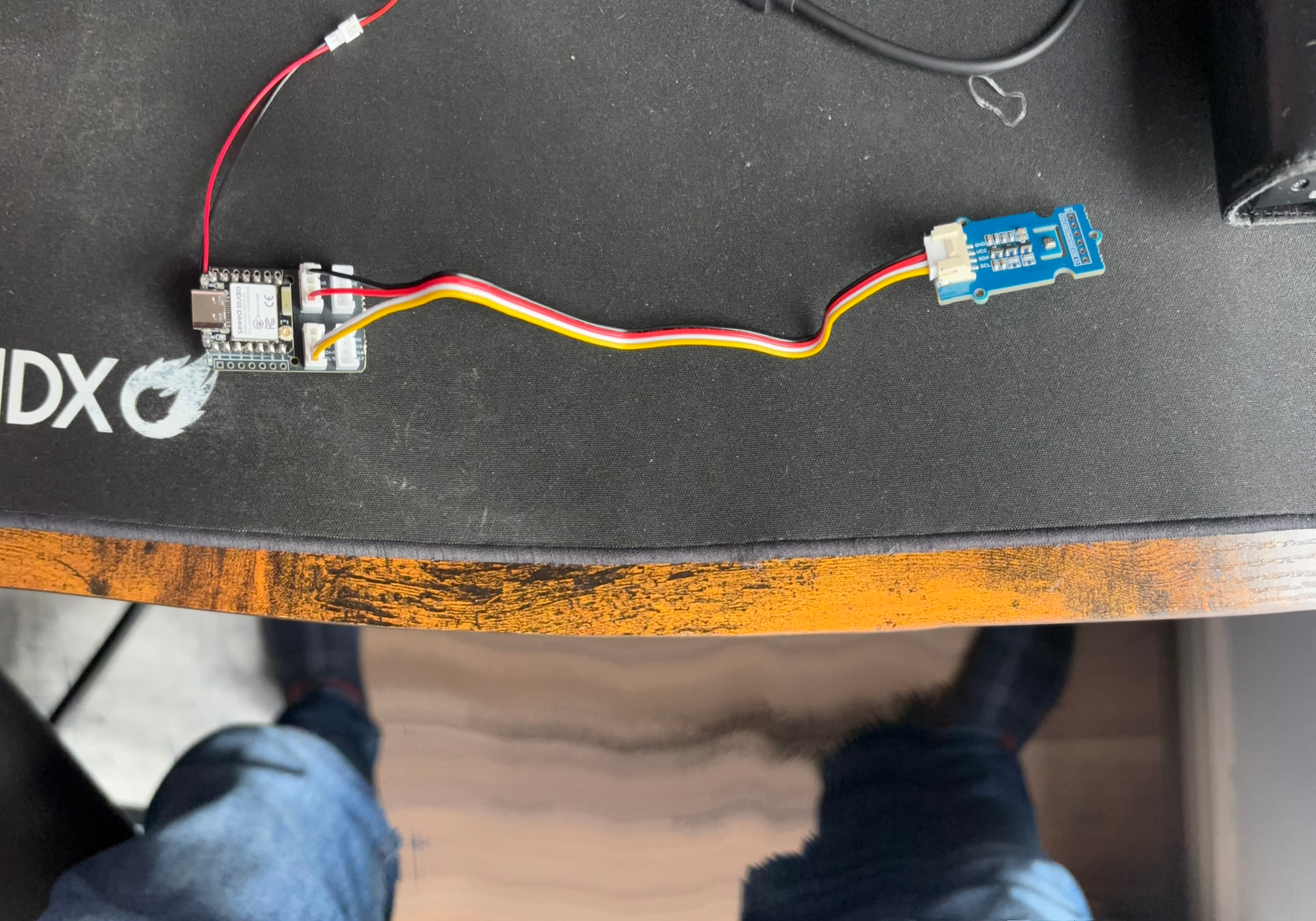
Improved photo here:
1 Like
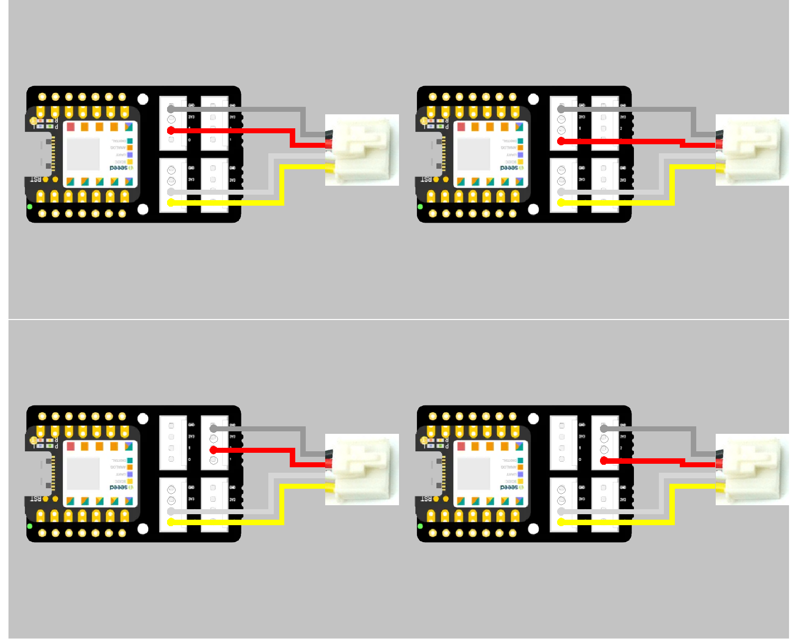
In this configuration you can use D0-D1-D2 as power pin based on the position

I call the data pins Data-A and Data-B where A is the lower of the 2 numbers and B is the Higher of the 2 numbers
So for example, ifyou construct 2 grove cables… One with red on Data-A(Yellow) and One with red on Data-B(White) you can accomplish the following combinations
Grove Connector and Cable
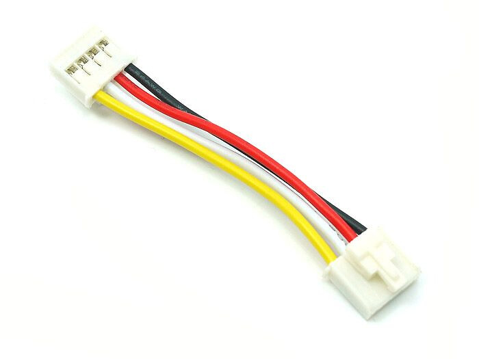
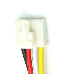
So for naming convention, according to this diagram, the connector will be oriented so the Black is to the left with the wires exiting to the bottom…. The clip connector (if equipped) will be on the top face this also matches the readable direction on the silk screen
The colors will be Black-Red-White-Yellow
The Pins will be GND-3v3-Data W-Data Y
So for naming convention, according to this diagram, seeed standard is to name the port buy the number of the data pin in the right most position in the grove connector, (Yellow Wire)
Typically the (white pin #) is = (yellow pin #+1), But this is not always true as UART and IIC are backwards
for example
the top row of grove ports are 0-1-2-5
the bottom row of grove ports are 5-7-8-9
as you can see… ports 5 are identical because they are an IIC bus
The unique of the IIC Bus is that multiple devices can communicate on this bus structure, as opposed to UART and others that are one port to one device configuration
I call the data pins Data-A and Data-B where A is the lower of the 2 numbers and B is the Higher of the 2 numbers
so for example.. at Grove Port 0, the Pins will be GND-3v3-Data B(1-White) and Data A(0-Yellow)
BUT for Grove Port 5 (IIC), the Pins will be GND-3v3-Data A(4-White) and Data B(5-Yellow)
AND for Grove Port 7 (UART), the Pins will be GND-3v3-Data A(6-White) and Data B(7-Yellow)
I’ve tried both ways of connecting to D1 (altering the cable and using the second Grove port) and both have no effect. My meter shows ~3V appearing on D1 both at the C6 pins on the Grove shield and at the SPI on the BME280. GND is continuous throughout. All sockets & wires are clearly labelled on the shield and on the BME280 so it’s pretty trivial to check that the wiring is correct.
The point is we have seen bad solder joints, in this case on the D0 pin may be limiting the voltage/current also be altering the connectors, it is possable something is not connecting correctly
by correctly i mean good physical connection
Did you say you tried connecting to Port 5, Port 0 and Port 1 and you got the same results?
You have a connection from the XIAO to the pins to the board to the grove to the other grove to the sensor and back… this is the pathway to check
this is also why i offered connection scenerios to the D0, D1 and D2 pins to see if they may function the same or different
The last option would be to power thru 2 pins by constructing a cable that combines the red on both Data-W & Y
The only other options i can think of is to try another XIAO chip type SAMD always takes back to basics and to try the Ardiono IDE and just use the basic code example to ensure something is not going wrong with the whole Bluetooth mess
This is a fun question, because we cant figgure it out… but it shows the beauty of the XIAO grove system… I need to see if i can dig up this sensor somewhere, and controlling power with pin… I am thinking some tests need to be done with and without pull up resistor and in analog and digital pin modes
When powering the BME280 from D0, the sleep current is 13μA. The current consumed by the BME280 is estimated to be 400 - 13 = 387μA.
1 Like
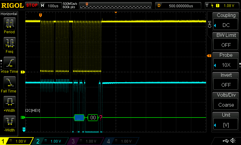
I am conducting experiments with C6 and the BME280 breakout mounted on a breadboard. When powering the BME280 from D0, data is obtained but shows no change whatsoever, and your issue was reproduced. D0 initially rises to 3.3V but then spikes down to around 1V after 500μs. This phenomenon may be affecting the BME280.
I’ll analyze it a little more.
EDIT:
To stabilize the VDD voltage, a capacitor was added. To simplify the sketch, the BLE portion was removed, and only the BME initialization function is running, observed with a digital oscilloscope.
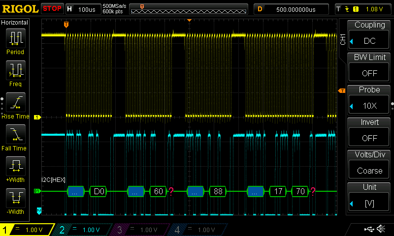
When powered from the 3V3 pin, C6 reads register 0xD0 and the BME returns ID data 0x60. When powered from D0, C6 reads register 0x00 and there is no response from the BME. Based on the waveform, initialization is not succeeding.
Proposals:
Try BME280 libraries provided by vendors other than Seeed
Use sleep mode instead of BME ON/OFF
EDIT:
Using Adafruit_BME280.h, you can power the BME from D0 and turn it ON/OFF. However, before initializing the BME, you must initialize I2C with:
Wire.end();
Wire.begin();
#include <Wire.h>
#include <Adafruit_BME280.h>

#define GPIO_BME280 0

Adafruit_BME280 bme280;

void setup() {
  Serial.begin(115200);
  while(!Serial);
  Serial.println("BME280 test");

  pinMode(GPIO_BME280, OUTPUT);
}

void loop() {
  digitalWrite(GPIO_BME280, HIGH);
  delay(100);

  Wire.end();
  Wire.begin();
  if (!bme280.begin(0x76)) {
    Serial.println("Could not find a valid BME280 sensor, check wiring!");
    while (1);
  }

  float temperature = bme280.readTemperature();
  float pressure = bme280.readPressure();
  float humidity = bme280.readHumidity();
  Serial.print(temperature); Serial.print(" "); Serial.print(pressure); Serial.print(" "); Serial.println(humidity);
  delay(100);
  digitalWrite(GPIO_BME280, LOW);

  delay(1000);
}
3 Likes
Yay! Solved! I can’t thank everyone enough for your help with this.
In summary:
- Yes, you can power the BME280 from a GPIO pin
- Use the Adafruit libraries, not the Seed libraries
- Toggle the I2C bus between raising GPIO and initializing the BME280.
Proof of solution:
Eddystone-UID beacon detected
Device: 98:88:E0:7C:71:B6
RSSI: -55 dBm
TX Power: -29 dBm
ID: X00b6
Temperature: 19.1
Humidity: 41
Pressure: 0983
…which is in agreement with my other devices.
3 Likes