XIAO S3 low performance voltage regulator

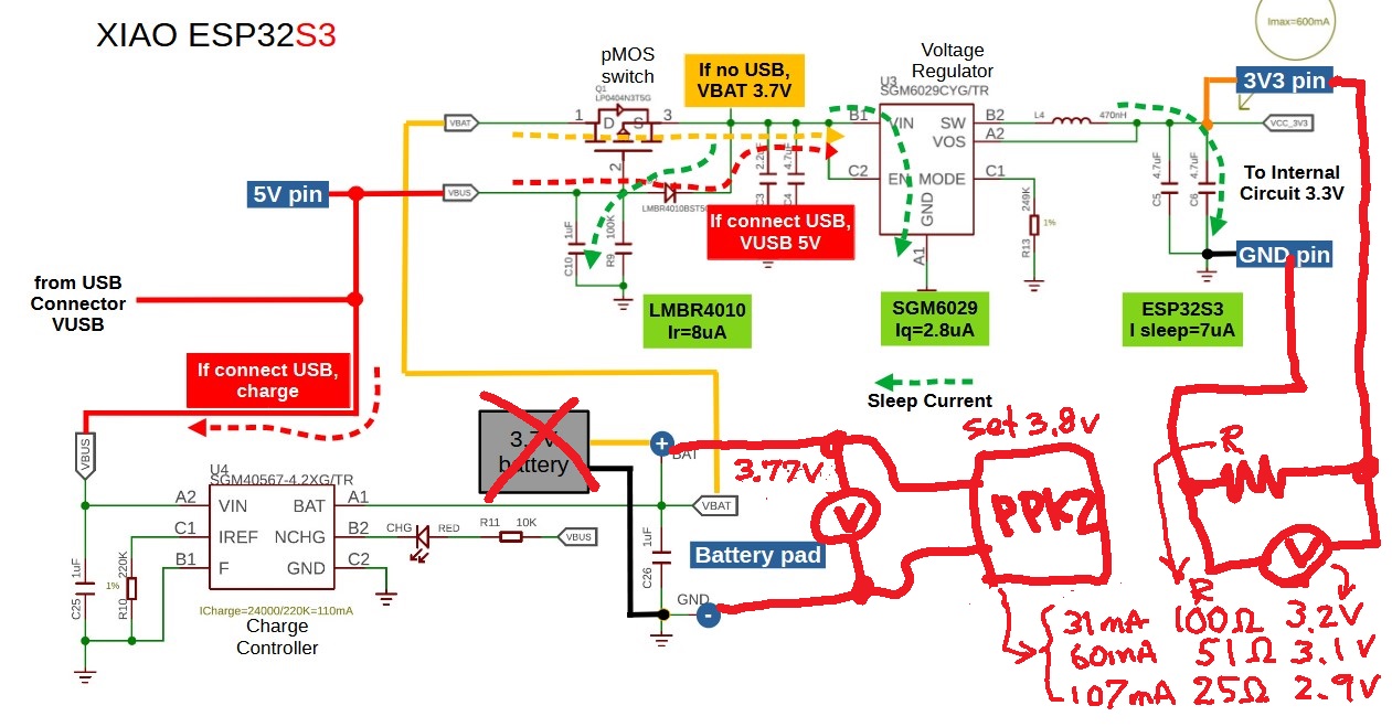
The Xiao S3 comes with a sgm6029 buck converter whose datasheet promises a 90% conversion efficiency.

However, that doesn’t seem to be the case, at least with my particular board when the power consumption isn’t very low:

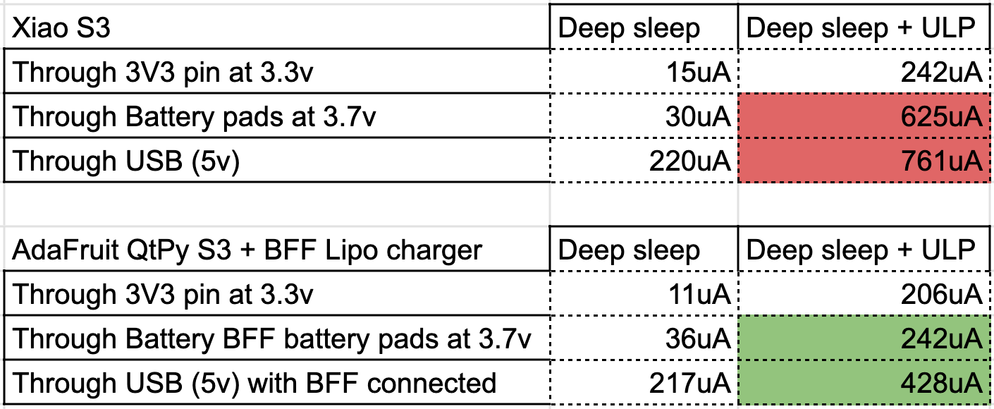
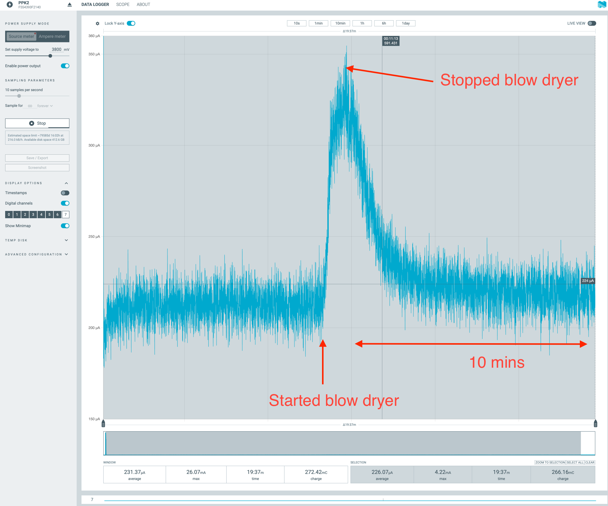
I measured the power consumption with the a Nordic PPK2:

  1. on the battery pins when supplying 3.7V .

  2. when injecting 3.3V directly to the Xiao’s 3V3 pin, which will give us the board’s load (it skips the regulator and will let us infer how much the regulator is consuming).

  3. And for extra reference, I also measured the power consumption through USB (which will have the overhead of the battery charger).

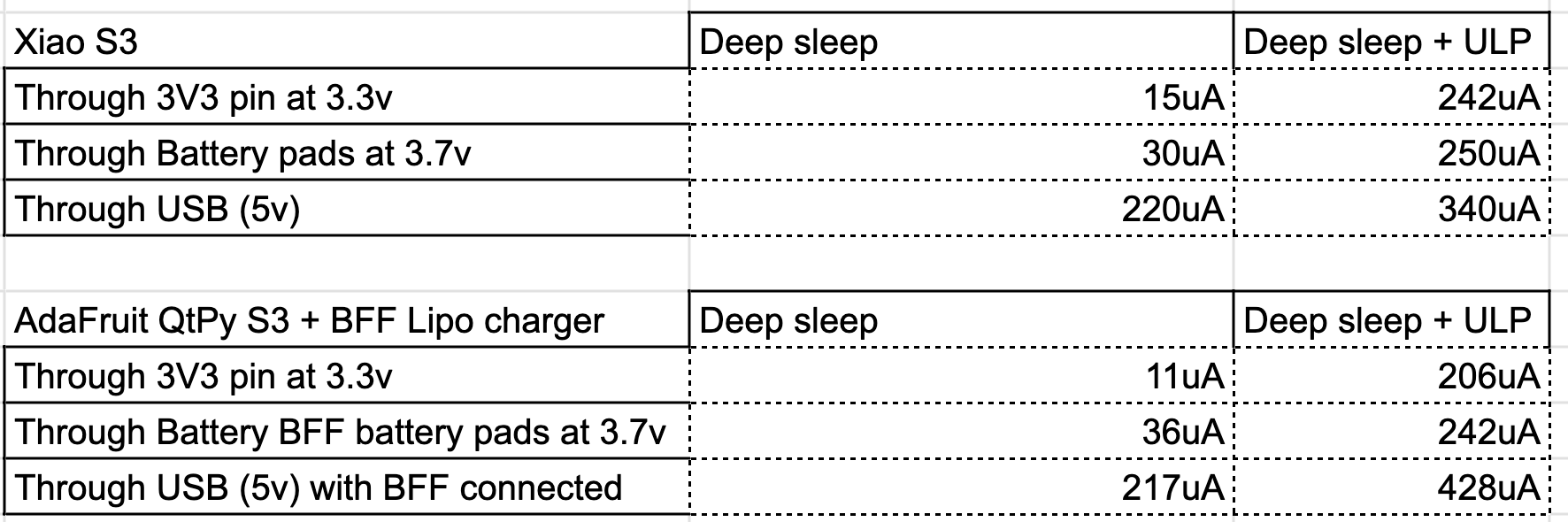
In deep sleep I get 30uA, which seems reasonable although it contrasts with the 11uA mentioned by msfujino at Comparison of Sleep Currents for XIAO ESP32C6, S3, and C3 and the 15uA I measured when I skipped the regulator.

But, when using the ULP during deep sleep (gathering ADC measurements) I get a whopping 625uA which isn’t reasonable (I get 242uA when skipping the regulator).

I get a similar behavior when measuring power through USB (although I get higher measurements due to the charger being on).

For comparison, I made the same measurements on an Adafruit QT Py S3 with a BFF Lipo charger attached. The Qt Py uses an a completely different LDO and charger but it helps to provide a ballpark comparison.

The QT Py has a behavior much closer to what I would had expected on the Xiao. However, I would love to use the Xiao since it’s cheaper and doesn’t require an external board for battery charging.

Any ideas of what could be wrong? I really hope I am doing something wrong or that my S3 board is faulty because I ordered a bunch of C6s which use the same regulator.

1 Like

@msfujino sorry to ping you directly, but since you created the original post, I thought you may have some insights on what could be wrong.

I am new to the forum, so I could only post two links in the post. Here is how I soldered the battery and the performance graph of the sgm6029. As you can see the performance should be > 90% with a load of 250uA and an input voltage of 3.7 .

1 Like

Hi there,
and Welcome here… :+1:
Nice work and breakdown… very good
I’m looking and can’t help think it’s because the 3.3V pin, injection is the issue here.
@msfujino is the power Ninja :ninja: so I’m certain he will reply. He’s as thorough as you are and we/I am lucky to stand on these shoulders of such giants.

GL :slight_smile: PJ
:v:

1 Like

Hi fons,
What is “ULP”? Where and how is it connected?
I’ll think about the efficiency of the regulator, but I need some time.

First, why don’t you see if you can reproduce my measured DeepSleep current? It should be noted that the measurements were taken with 3.8V applied to the battery pad and at a room temperature of about 25C. Diode leakage current is greatly affected by temperature.

1 Like

fons,

To answer your question, I connected a resistor to the 3V3 pin and measured the power supply input current. I observed that as the load current increased, the 3.3V dropped much more than expected.

The power supply input was 3.8 V from ppk2 to the battery pad, and a constant voltage of 3.77 V was confirmed with a digital multimeter. 100, 51, and 25 Ohm resistors were connected to the 3V3 pin, and the current was measured with ppk2, and the voltage on the 3V3 pin was confirmed with a digital multimeter. The result was that when I connected a 25 ohm resistor, for example, the 3V3 pin dropped to 2.9V, which no longer seemed to be the output voltage of the 3.3V regulator.
I wish I could check the voltage between the regulator and the PMOS switch, but I cannot access it under the can.

If possible, could you please check if the voltage drop is reproduced there as well?

edit
It may be that the regulator cannot output a large current without cooling the heatsink pattern on the backside of the board.

1 Like

It is important to remember that this is a small device… it cant be expected to do heavy lifting

Thanks a lot for your answers @msfujino !

It’s the Ultra Low Power co-processor (present in eps32’s s2/s3 and c6). It runs in parallel with the main CPU and can run during deep sleep. But for the sake this question, you can just consider it as some load (<1mA) which exists during deep sleep.

See ULP RISC-V Coprocessor Programming - ESP32-S3 - — ESP-IDF Programming Guide latest documentation for details.

I can share the full esp-idf project if you are willing to test it. If you could measure the current during deep sleep while running the project we could conclude whether there is a problem with my hardware.

I did! :slight_smile: (although with 3.7v), it’s on the power consumption table I shared above (Through Battery pads at 3.7 + Deep sleep entries indicate: 30uA for the Xiao and 36uA for the AdaFruit).

I measured again at 3.8v but I didn’t see a considerable difference. So, there is a 3x current difference with what you measured in deep sleep.

This is what I get from PPK2 when injecting 3.8v on the battery pads with a 100ms zoom:

There are peaks every 12ms, I was attributing those peaks to the regulator, but now I am not sure. 12ms seems too wide, so clearly something’s up.

I could attribute it to a software problem but that doesn’t explain why the same view (with exactly the same code), when injecting 3.3v (actually, injecting 3.38V) directly to the 3v3 PIN is:

15uA seems very reasonable.

Note also that, unlike my other boards, the Xiao seems to be using a 0.1 version of the chip (as shown by the flashing tool) as opposed to the Adafruit board (and another Waveshare board I have) which use version 0.2 of the chip. Maybe this has something to do with it? Could you share your chip revision?

Sure I just did! Here are the results:

Note that a variable resistor was used (since I didn’t have fixed resistors for all the values you supplied and I don’t own an electronic load) so the results won’t be super precise:

I added an extra measurement with a 1971 Ω resistor

I get a steady voltage of ~3.75V from the PPK2 during all the tests except for when the 1971 Ω resistor is used, where I get 3.796V

1 Like

Sure thing! In fact my use case entails using the ULP during deep sleep, which should consume very little power. Honest question, why did you infer I expected to do any heavy lifting from the device?

Hi there,
Bringing the receipts he does, :ninja: LOL :+1:
I can add that if you attach with a clamp to the bottom it will indeed reduce the heat felt on the MCU when using the camera I feel extending the life and improve the performance as well.
I also think it’s under designed for the expected performance we need from this MCU IMO…
seems as soon as you LOAD it down things go Toasty pretty fast. :face_with_peeking_eye:
HTH
GL :slight_smile: PJ
:v:

more current = more voltage drop

Forget this, my XIAO S3 has a revision 0.2 chip, I mistook it for the revision of the QT Py.

Also, I now realize that I mistakenly measured the deep USB power while the charging LED was on (it turns off after a few seconds).

Leaving us at

However, that still doesn’t explain the difference when using the battery pads (which should result in the charger being off) if anything, it should be consuming less than 340uA and definitely not 625.

1 Like

OK, mystery solved. I redid the battery pad soldering and the power consumption went down to a reasonable value. I triple checked it when I did it the first time, but my guess is the cables may have been touching the GPIO pin pads. This is the final result:

I wish that the battery pads were on the top side of the board and I also wish I had reched the soldering earlier. I spent a week trying to figure this one out.

Anyways, the conclusion is that the Xiao has a great power consumption during deep sleep, comparable to the QT Py S3 but way cheaper in both space and price since it comes with the charger bundled in.

1 Like

HI fons and every one,
I am glad that the problem was resolved while I was sleeping!.

I would like to review a few things.

OK, mystery solved. I redid the battery pad soldering and the power consumption went down to a reasonable value. I triple checked it when I did it the first time, but my guess is the cables may have been touching the GPIO pin pads.

I actually suspected the wiring problem when I first saw the photos of fons soldering, but I decided that fons was experienced in electronics and didn’t point it out. I regret that. Here is a picture of my soldering for reference. I use thin leads and glue them in place so they don’t move.

However, that still doesn’t explain the difference when using the battery pads

I think the reason why the sleep current is 30uA when powered from the battery pad is due to the leakage current of the LMBR4010. According to the datasheet, it is 8uA at 25C, but it easily doubles if the temperature rises even slightly. There is also a large individual variation (confirmed with 3 pieces). If the current increases significantly when the can is warmed by warm air, I think the diode is the cause.

I started the experiment with a large load current because I saw the efficiency graph posted by fons and mistakenly thought that there was a problem with the efficiency at mA load. However, I am glad that I recognized the problem of heat generation in the ESP as a result.

1 Like

I’ve also realized that temperature is playing a big role.

During my tests I was turning on the main CPU periodically and connecting to Wifi. This raised the temperature of the CPU (or other components like @msfujino has pointed out), which apparently causes the board to consume more power.

To isolate the issue I have let the board cool, modified the code to stop waking up the CPU periodically (but leaving the ULP on) and hit the board (very unscientifically) with a blow dryer to raise its temperature. This is the power consumption profile:

It’s interesting how the power consumption doesn’t recover further after 10 mins (I guess that before hitting the board with the blow dryer it didn’t reach the baseline).

After having the board on for a while (with the periodic wakeups of the main CPU) the “Deep-sleep + ULP” consumption raises to 340 from the 250 I meassured at XIAO S3 low performance voltage regulator - #12 by fons

I still need to investigate, but it would suck if the diode is to blame for the extra 90uA

I think the only way to confirm this is to open the can and replace the diode.
I have replaced the diode as shown in the link below.

Shutdown current of LoRa-E5 mini, from 72uA to 3uA by replacing LDO and Diode - #2 by msfujino

I am still mastering TTH soldering but … so SMD is going to be a challenge, but I will see what I can do.

I just happen to have ordered a cheapo heat station from Aliexpress which should be here in about a month.

BTW, do you also recommend the GS1010 for the S3?

There is a comparison of the leakage currents of diodes. If the current does not flow enough to worry about forward voltage drop, it is better to use a silicon diode than a Schottky diode. As you can see from the characteristics table, the characteristics of the GS1010 silicon diode are overwhelming. If you want to use a Schottky diode, you may choose SBR1U200, which is called SuperBarrierRectifire with low leakage current.
I think GS1010 is available, but there is no reason to stick with it.

The link below has a picture of the inside of an ESP32C3, not of an S3 or C6, but it may help. The Schottky diodes are marked “KV”.

XIAO ESP32C3 and I2S. How to? - #21 by Rob_Fowler