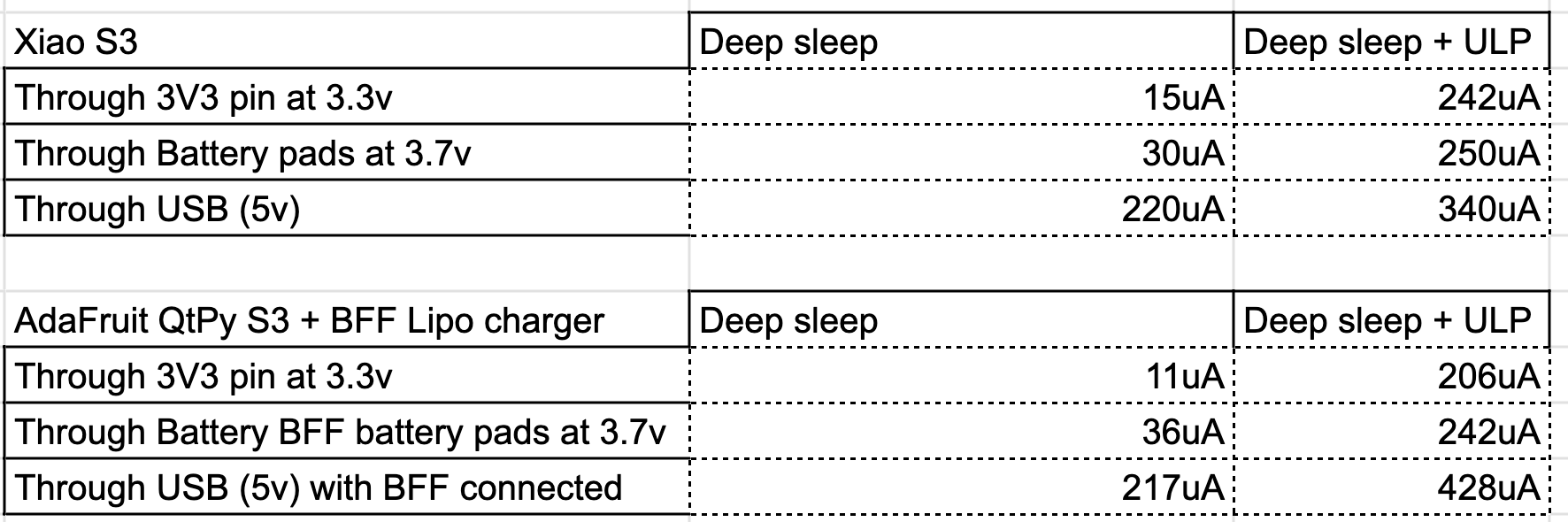
OK, mystery solved. I redid the battery pad soldering and the power consumption went down to a reasonable value. I triple checked it when I did it the first time, but my guess is the cables may have been touching the GPIO pin pads. This is the final result:
I wish that the battery pads were on the top side of the board and I also wish I had reched the soldering earlier. I spent a week trying to figure this one out.
Anyways, the conclusion is that the Xiao has a great power consumption during deep sleep, comparable to the QT Py S3 but way cheaper in both space and price since it comes with the charger bundled in.