I’ve been doing extensive low-power testing on the XIAO nRF54L15, and overall it’s a very impressive board—especially now that the nRF54L15 has Arduino support. It has the potential to be one of the best ultra-low-power platforms available.
However, I’ve run into a significant limitation related to the onboard voltage regulator.
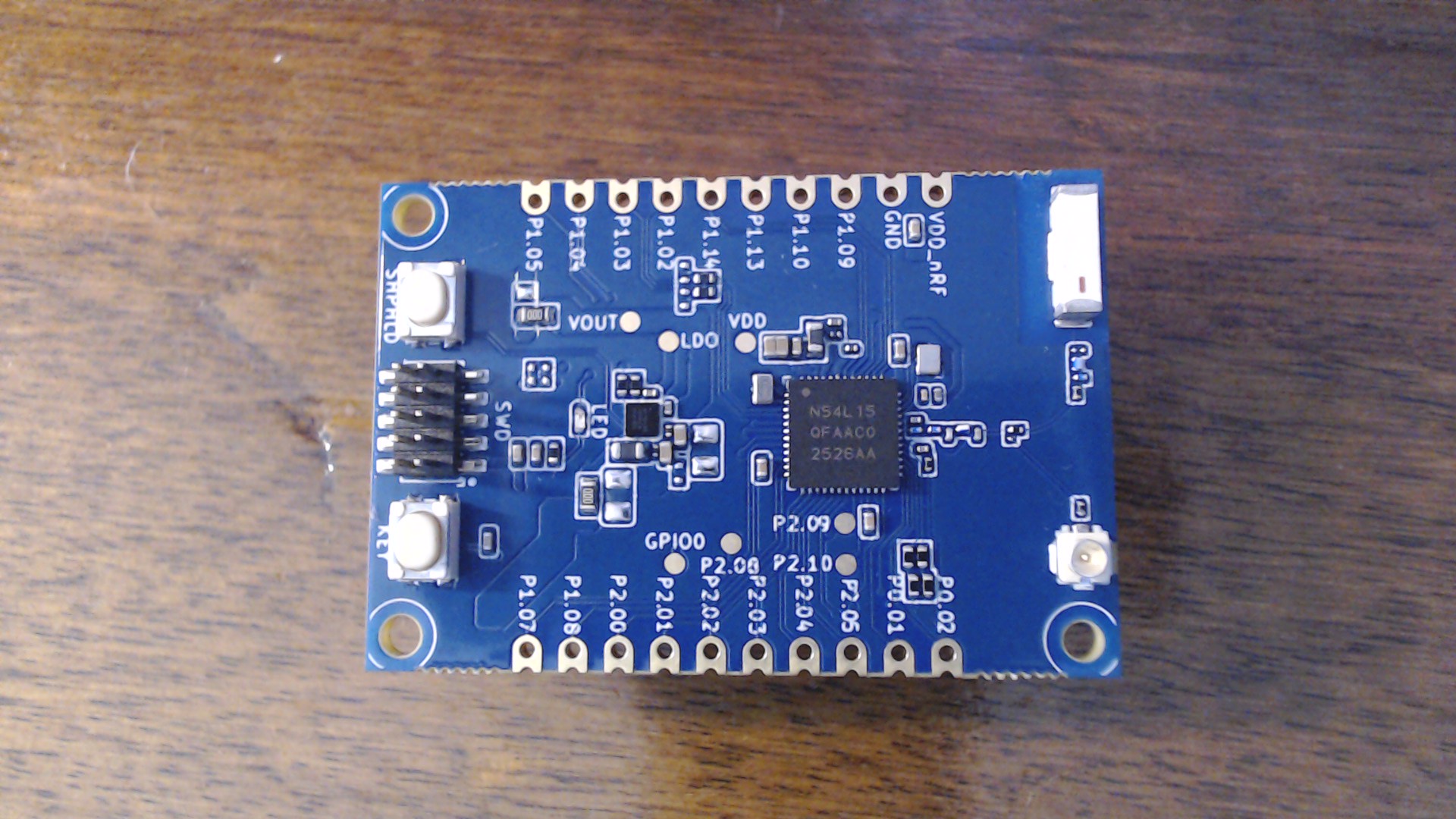
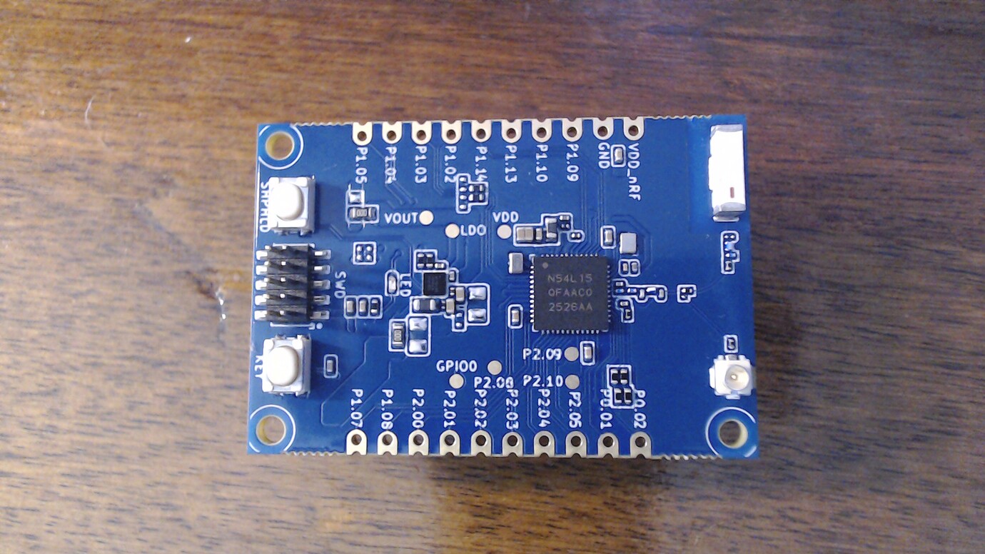
The board uses the TPS62843, which is a high-quality step-down (buck) converter and works very well when VBAT is higher than 3.3V (e.g., LiPo scenarios). In that region, efficiency is excellent and current consumption is very low.
The issue appears when VBAT is around 3.3V—exactly the range used by coin-cell batteries. At this point, the regulator enters a near-dropout region, and current consumption increases significantly. Below 3.3V it improves slightly, but remains higher than expected for ultra-low-power applications.
This behaviour makes the current design difficult to use with coin cells or other low-voltage sources, where minimising quiescent current is critical.
Suggestions for Future Revisions
To make this already excellent board more flexible and suitable for ultra-low-power designs, I’d suggest:
Use an ultra-low quiescent current LDO instead of (or alongside) the buck
The antenna switch design is good, but adding solder jumpers or easier power gating would allow users to fully disable it when not needed
Buck converters are excellent for many scenarios, especially with higher input voltages. However, for ultra-low-power, low-voltage applications (like coin cells), they are not always the best choice—particularly near dropout.
Thanks for the great work so far—this board is very close to being ideal for ultra-low-power development.
So, The present XIAO nRF54L15 power choice is a TPS62843 buck regulator, and that part is a very good fit when the input is comfortably above 3.3 V. TI positions it as an ultra-low-IQ step-down converter for 1.8 V to 5.5 V input, with strong light-load efficiency.
But Yours and others , minne too, complaint is also valid: for coin-cell / near-rail sources, a buck-only board is not the ideal universal answer. A buck can only regulate downward; it cannot boost a sagging primary cell back up to 3.3 V. So once you are designing around CR2032-class or other low-voltage primary cells, you are in a different regime than “LiPo into a 3.3 V rail.” That is exactly the problem Nordic is targeting with the nPM2100, which they market specifically as a PMIC for primary-cell batteries with an ultra-efficient boost regulator, ship/hibernate modes, and fuel gauging.
Agree:
the SGM2040 is also reasonable. The XIAO nRF52840 schematic shows an SGM2040-3.3 regulator, and the SGM2040 itself is a very low-IQ LDO with about 1 µA typical quiescent current and low dropout. For low-current designs near 3.3 V, that can be a better behavioral match than a buck stage that is being asked to live close to dropout. PMIC again ..
Thank you for the reply! I am happy others feel the same way.
Also, I’ve never heard of nPM2100, but looking at the specs, it sound amazing! I am tempted now do create my own, since both IC are in stock in JLCPCB(no advertising intended).
I will wait now for a nRF54L15 module I’ve ordered, so I can test different programmers chips (like the Raspberry Pi Pico, and after i will create a board with both nPM2100 and SGM2040 to perform tests on it.
Absolutely , and the Link has the schematics and board stuff too, they built this for SEEED to show how the Power Management IC could improve the design, No worries about JLPCB either I used Easy EDA for all of them,they have a parts list that is off the chain, if you look on here I have many boards made and shipped successfully with XIAO in the driver seat maybe one or two that are just grove accessories. My hope is the 15L and roomerd:man_detective: 20M will be the Lowest power and best Xiao for battery powered devices. Those Seeedineers are pretty crafty , so I would expect GOOD things to come.
HTH
GL PJ
Ps ,You can order one of the test boards above for yourself too from JLPCB the info is in the links. BTW - for Less than what a MOthrFOkn Can of Coffee (stupidity that is tariffs) costs. The BLE implementation alone is worth it, the code included is very sleek and works better than any I have seen to date. shipping current 15-45 na. Vikings RULE
A 3.7V coin cell would be a good option for you. Do you have charging turned off. Is the XIAO charging your 3.0V coin cell at 4.2V when usb is connected?
I have been learning about MCUs, Zephyr and Zigbee in order to complete a simple project to build an occupancy sensor using a simple digital hall switch that is battery powered and integrates with my Home Assistant via Zigbee. This small project is a way for me to learn more about embedded development.
Current equipment
nRF54l15 DK
Power Profiler Kit 2
Seed Xiao nrf54l15
drv5032 hall sensor (wrote a driver for this)
I have been working with the nRF54 DK up to this point and have managed to get the power usage down to around 20 µA.
At this point I moved to getting the code working on the Seeed Xiao nRF54l with the goal of achieving a similar power usage to the DK. I have struggled with this and I’m seeing things I don’t understand.
For example the voltage supplied to the Xiao seems to make a big difference to how much power is drawn. Setting the PPK2 to supply ~3v increases the consumption of the Xiao compared to ~3.4v where it uses roughly the same as the DK.
Am I doing something wrong with the way I am measuring the power draw on the Xiao or using the PPK?
Are there alternatives to the Xiao e.g. I’ve seen WROOM module used in other projects I have learnt from?
Eventuially I want to create a PCB to hold the Xiao (or an alternative), battery cradle for a CR2450 or similar and the digital hall sensor.
This is a journey for me to learn new skill and produce something useful that I can be proud of.
Hi. You cannot use 3v with Xiao nrf54l15 board. Anything from 3.3v down will make the current spiral out of control. This is due the wrong design, as they used a buck converter for power.
If you choose to go for a Xiao nrf54l15, or even a basic nrf54l15 board , you can use Arduino IDE for programming. It’s a bit hit and miss with Zigbee at the moment, but support will get better. BLE works as it should.
So , all of what you want is available, however te Xiao has some caveats to say the least in it’s present form. Have a look at the superior reference design nordic made for seeed, You will learn some things if you can read the schematic , et al..