You measure board current, not chip sleep. XIAO includes charger and regulator circuits. These consume milliamps even in sleep. BAT pin powers charger section continuously. This explains the approximately 10 mA reading.
If you’re getting 10mA while in sleep, you’re not actually going to sleep. My XIAO nRF52840s idle around 40uA and in deep sleep go down to below 10uA. This is measured board power using a external current shunt, not chip power.
TL;DR: you’re doing something wrong. Try disconnecting any peripherals and doing an erase-flash and re-flashing the deep sleep example script and measuring again in the PPK. even at full load, my 52840s don’t go above 10mA so either your module is horribly broken, your code is horribly wrong, or your ppk isn’t accurately measuring things.
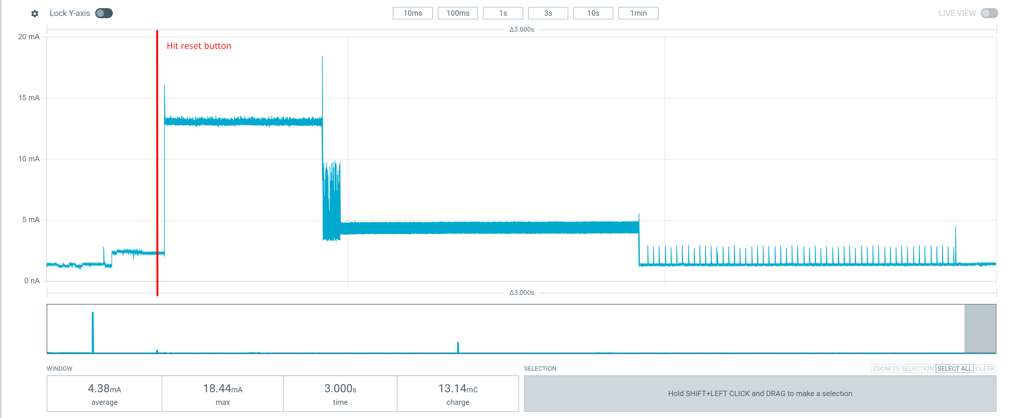
I’ve tried erasing the flash, and uploaded the code again, I see some improvements, but still not the expected.
What I did:
Downloaded zml_clear.uf2 from Bootloader · joric/nrfmicro Wiki · GitHub and put it on the folder from xiao nrf52840. The device then rebooted. Then I uploaded the code from msfujino example. First I got a compiler error:
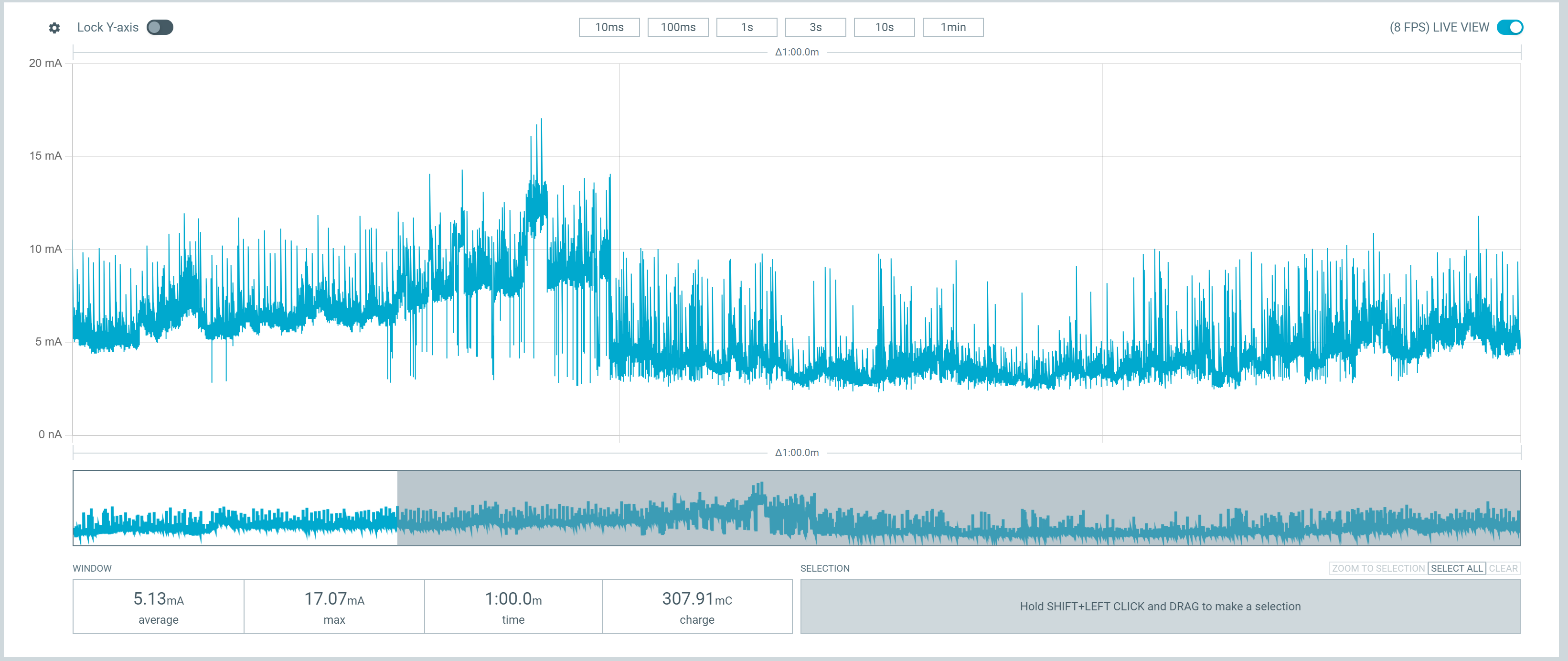
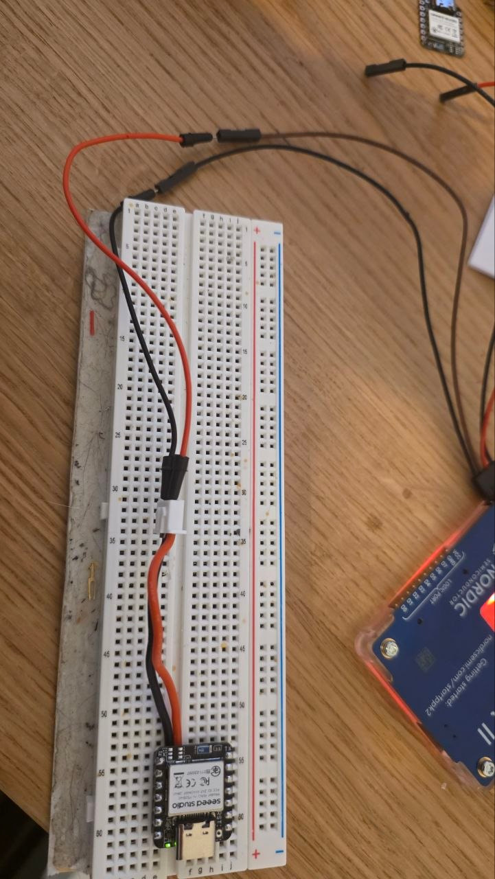
To measure power, I put PPK2 on Source meter, and set it to 3.3v, and linked the pins to 3v3 + GND on XIAO nRF52840. I noticed that if I used the battery pins instead, the current usage would always be 10mA (in Ampere Meter mode of PPK2).
Keep in mind, I don’t have anything connected to the XIAO nRF52840 beides the PPK2 for measuring the power consumption. No USB too.
I am still new to this world of XIAO, so I don’t know if I’m missing a step or doing something wrong. My only goal for now is to get the lowest power consumption possible, since I’m trying to achieve something that will be battery powered.
Please try the sketch for the nRF52840 available at the link below. At the very least, it should not produce any compilation errors. Please use BSP version 1.1.12.
Connect the brown lead of the PPK2 to the + terminal of the battery pad and the black lead to the – terminal of the battery pad, then apply 3.8V.
Is there a while(!Serial) statement in the sketch?
Why not start by testing whether the XIAO is working properly using Blink.ino?
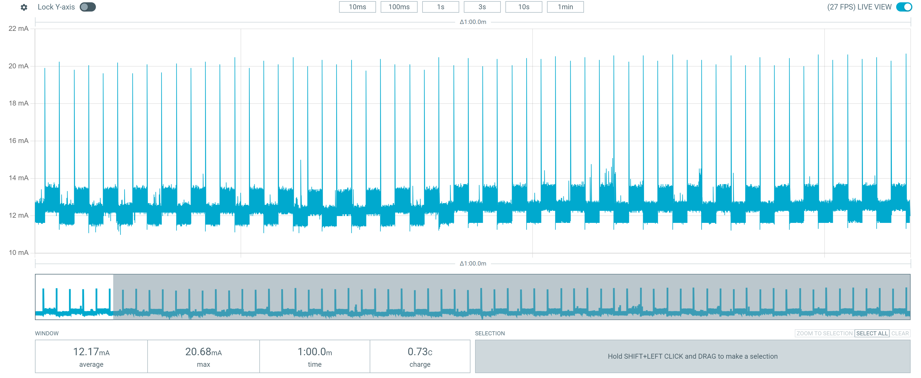
Hello, I’ve uploaded the blink program, and it works. For reference, the measured current is ~12mA (measuring exactly how you mentioned, using the battery pads, and applying 3.8v).