I have a little « issue » regarding power supply for a XIAO ESP32-S3 board.
I made a little weather station which fetch datas from openweathermaps and display them on a 2 inches TFT screen connected via SPI. Connected to the the Xiao are (beside the screen):
2 push buttons. One is for navigating between different cities (4 in total) and the second one is to access a page to display datas coming from an outdoor station in my garden
A temperature and humidity sensor connected via I2C for indoor measurements
A LED strip (ws2812b addressable leds) they change color according to the local temperature in the 4 cities I am monitoring and a 5th LED as an indicator of the connection with the garden station.
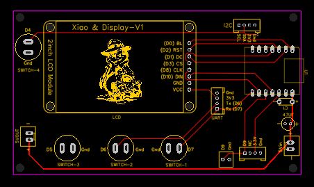
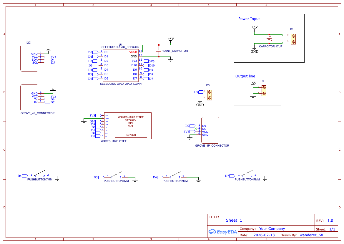
The whole system is on a little PCB I designed for this. On this PCB, for power supply, I have a « 5V in » screw terminal which routes to the 5V pin of the XIAO.
Now to the « issue »:
When powering the board through this 5V line (I use a 5V 2A power adapter) the system stops after a couple of hours of use. The Xiao becomes unresponsive and if I try to reset it (either via the reset button or by unplugging it and plugging it back again), it stays unresponsive for a couple of minutes. The only option is to wait for a moment and powering back on via the USB socket.
The other think I have noticed when the XIAO freezes:
When powering via the 5V pins: the tension at the 3.3V lines is up to 4.3V
if powering through USB I only get 2.4V on the 3.3V lines.
This last for a little while, then all goes back to normal.
If I only use the USB socket for powering, no issues at all, the system is running smoothly without an issue.
Is it something some of you experienced when using the 5V pin for powering a system? And most importantly any idea why this is happening?
Thanks in advance for your answer
Have a beautiful day
Alain
Oh and when using the 5V pin, I always make sure I keep the the USB socket unplugged…
Yes the 3.3V line is referring the the XIAO’s 3V3 pin…
I will try to post later the schematics (I don’t have currently access to the Harddrive where it is stocked). Anyway, the pcb is pretty simple it is much more an extension board than anything else, I will look into posting it later on
But then why the probleme only occur when powering via the 5V line and not if powering via the USB?
If I may add, Based on the information you provided, this looks much more like a power-path issue on the PCB rather than something related to sleep or firmware.
The biggest clue is that your system works perfectly when powered through USB, but eventually freezes when powered through the 5V pin. That strongly suggests something happening in the external power path or board layout.
A few observations stand out:
1. The 3.3V rail reading 4.3V is not normal.
The 3.3V rail should never exceed about 3.3–3.4V. If you really see ~4.3V, that indicates something is being back-driven or mis-referenced, or there is a power path issue somewhere on the board.
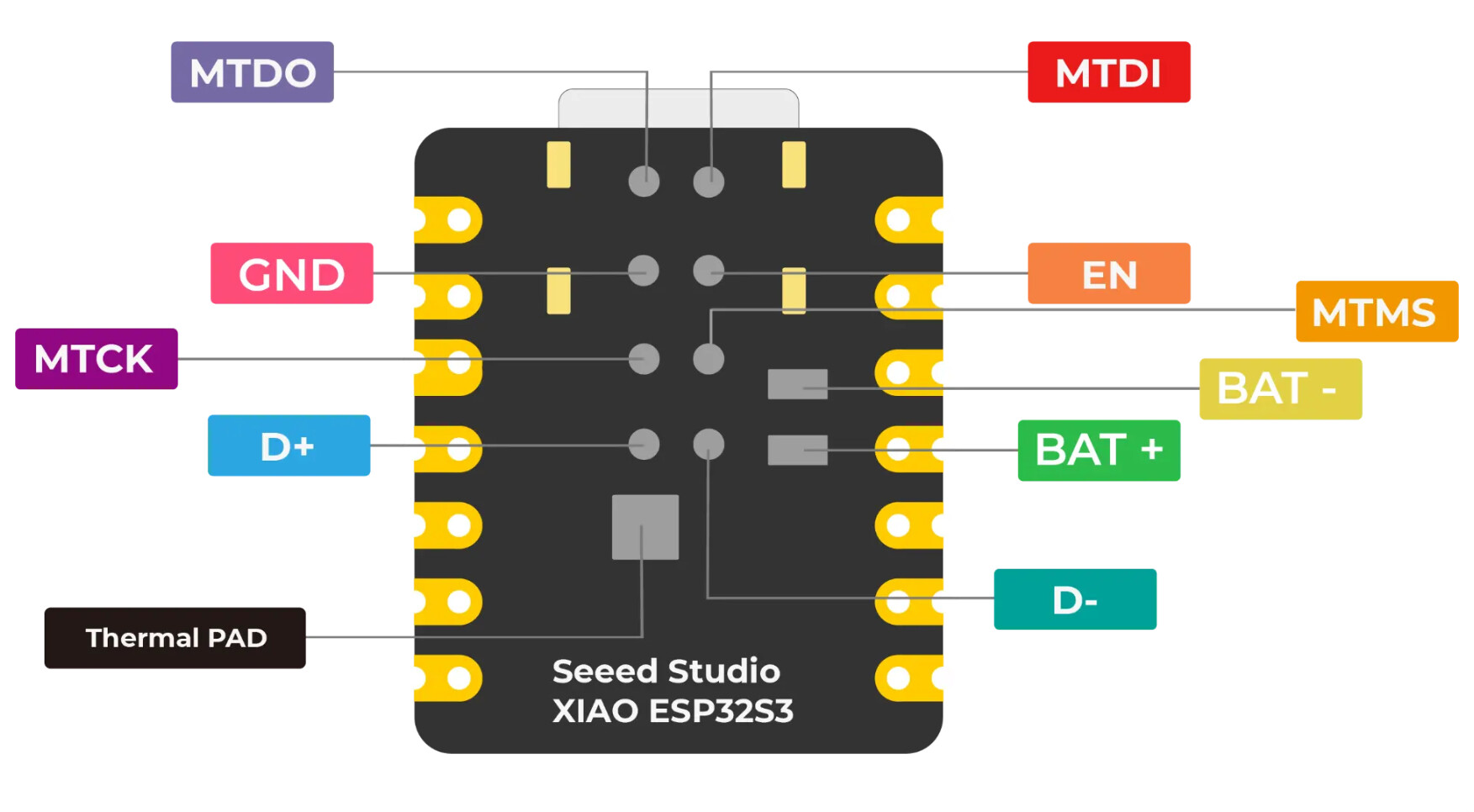
2. The XIAO 5V pin is essentially the USB 5V rail.
When using the 5V pin as an input, Seeed recommends placing a diode between your external 5V source and the 5V pin. This prevents current from feeding back into the USB power circuitry and avoids strange power-path behavior.
3. External peripherals can backfeed the MCU.
In your case there are several devices connected that could influence the rails:
WS2812 LED strip (common source of backfeeding)
SPI TFT display
I²C sensor pullups
Custom PCB power routing
WS2812 strips in particular can sometimes feed power through the data line if their supply and the MCU power do not rise/fall together.
4. Current spikes may be stressing the supply.
WiFi + TFT + LED strip can create short current spikes. Even with a 5V/2A adapter, poor decoupling or thin PCB traces can cause voltage dips that eventually lead to a lockup.
Things I would try first
Add a Schottky diode between the external 5V supply and the XIAO 5V pin.
Check the LED strip wiring
Ensure common ground with the XIAO
Add a 330–470Ω resistor in the data line
Add a large electrolytic capacitor (470–1000µF) across the strip power rails
Measure the rails during operation
5V at the XIAO 5V pin
3.3V at the XIAO 3V3 pin
If possible, use an oscilloscope to see transient drops or spikes.
Test with the LED strip disconnected Do this one first IMO.
If the freeze disappears, the strip or its power transients are likely involved.
Inspect the custom PCB power routing
Especially check that nothing is accidentally tied between 5V and 3.3V nets, and that the TFT or other modules are not injecting voltage into the 3.3V rail.
Given that the board works reliably when powered from USB, the ESP32-S3 itself is likely fine. The evidence points toward external power routing or backfeeding somewhere in the system.
If you can share the power section of your PCB schematic, it would probably make the root cause easier to identify.
Hope this helps — it sounds like a nice little weather station project!
Hello,
First thank for you thorough and detailed answer earlier.
So to answer your questions
About the of the diode: it supposed to be placed between the screw terminal (5V in) and the 5 V pin correct? I totally fail to understand its role: “This prevents current from feeding back into the USB power circuitry” this is the part I dont get… I am not challenging anything here, it is just I cannot wrap my head around its function… If the diode is between the screw terminal and the 5V pin, it will prevent the current going back along the line between the 5V pin and the 5V power supply no? I don’t understand how it will prevent feeding back in the USB?
“Does the Power out (5V) go to the LED strip ?” → Yes exactly, and the signal is coming from one of the remaining free pin (D9)
“Are you initializing any Pull up Resistors ?” you mean for the press button? Yes I use the internal ones… something like: “pinMode(BUTTON_HOME_PIN, INPUT_PULLUP);”
As for putting the code here I don’t know how to do it, I use tabs when writing the sketch and there are a lot…
And no I don’t have tried without the strip, I am a little wary to damahge the board using the 5V in… so not really keen to run any trials to be honest
I have a XIAO ESP32-S3 running non-stop using a very similar setup to you, a 5V power supply (in my case a DC-DC converter from a 12-15V input), no series diode. I don’t have the USB connected.
I’m not sure about the 4.3V on the XIAO 3V3 lines? I use WS2812 with 5V supply and driven by 3V3 (from XIAO) and haven’t seen any problems with power fed through the data line
Since you don’t notice any heat buildup, I’d start with checking the code works 100% from 3V3 supplied to the XIAO and no USB.
If you use the </> tab you can add your test code.
Great… So the Diode is protection from a second source or the 5V it was intended to be an output BTW. for powering small sensors that didn’t draw a lot of current. It’s only by way of th schematic the common point could be injected a 5V besides what is created from the USB being plugged in. The DIode then would allow that as input is all.
Further , Since we can’t see the code so just feeling around in the dark…
just unplugging the status LED string certainly wouldn’t hurt anything but WOULD indeed verify the Strings current and switching is NOT affecting the operation. DO that and test again.
Hello,
Thanks for your answer.
“I’m not sure about the 4.3V on the XIAO 3V3 lines?” → When the XIAO freeze, the screen switched off (no backlight anymore) so I wanted to be sure it was still powereed, and when I measured the tension at the 3.3V lines I got 4.3V. But then after letting the board resting for a couple of minutes and re-powering it through USB, the tension was back to 3.3V.
“I’d start with checking the code works 100% from 3V3 supplied to the XIAO and no USB.” → you mean powering the XIAO with 3.3V? And having a separate power supply for the LEDs?
Have a nice day
Alain
Hello,
Thanks for the explanations regarding the role of the diode.
“just unplugging the status LED string certainly wouldn’t hurt anything but WOULD indeed verify the Strings current and switching is NOT affecting the operation” → I will do it, but I need to have time ahead of me to sit by the board and keep an eye on it as the issue happen after a while and I have no clue how long it takes from the moment I plug the whole system and the issue occurs. I just hope that the problem isn’t somewhere else and I will not fry the board then…
As for the code I will try to merge all the xxx.h and xxx.cpp files which constitute my sketch in a single one, to post here but it is going to take me a while …
I wish you a good day
Hello,
Thank you for your answer…
There are few things I don’t understand how to implement:
“add additional ground return paths to the power supply, external to the XIAO” → Do you mean having a wire “outside” the PCB from the LEDs strip to the power supply?
“check switching logic… sourcing or sinking current thru the GPIO Pins and duty cycle of led power” → I am not sure I fully understand how I am supposed to do that? Would you mind elaborating?
“if you had a thermal camera” → I don’t have one so I guess I can’t really do any measurement there…
“can you limit the current at the power supply? (Variable Power Supply try 1Amp max)” → I will have a look if I have one which only provide 1A Max…
“you may have to design a parrallel power supply for the led system”-> but isn’t it already the case? I mean the 5V out on my PCB is directely connected to the 5V In, so I was in the assumption that it was acting a bit as a power distribution board… Do you mean I should have one 5V power supply for the Xiao and one for the LEDs?
As for batteries and heatsink I do not have any of those with me so I will have to put that on the “to order list”
Have a nice day
I will try find the reason for the 4.3V by connecting similar devices to what you use (though I don’t have the same LCD).
The 5V pin on the XIAO (Pin 14) is just routed to VBus (from USB). So essentially the inline diode would be to prevent VBus feeding back into your 5V supply. If you don’t used USB and 5V at the same time then there is no need for the diode.
I might have found the culprit, I just noticed I forgot to solder the Gnd pin of the XIAO on the PCB, such a stupid mistake
I am now running the system with a 5V 1A power supply and without the LED strip and we’ll see what happened…
I have noticed that the 2 pins where the push buttons are connected (I am pulling up the internal resistor in my sketch for those) have a 3.8V tension? regardless of the power supply (external 5V or USB). Those pins are D6 and D7 is it normal? All the other ones are at 3.26V…
if you have some type of gethub or something you can PM PJ and get it to him directly
I know as far as code… some timer code will internally lock up due to hitting the 16 bit limit… but because you were stating power issues my vote is still thermal/current related