So appears your making progress, Good keep testing and observing and Documenting, Props to you for going right to PCB, most folks are too chicken to do it
As stated , the diode is ONLY needed if you plug both the EXT 5V and the USB at the same time.
The GNDS need to be Common. that will nerf things up in a hurry. Use your Ohm meter or continuity tester and check all the VCC’s and GND’s
If you are using the WIFI, it will require a strong power supply and good filtering as well. the 2A. should be enough to do the job well.
Keep going you will get it nailed down, it looks very good.
Hey there,
Thank you so much for your kind words of encouragement, they mean a lot…
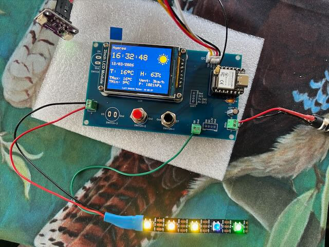
So I think I nailed the problem, it was a missing blop of solder on the Gnd pin (it was for the female headers where the XIAO is sitting). I somehow forgot to solder it…
So thanks to @cgwaltney for mentionning addding a ground line, it is while trying to figure out how to do it that I noticed the misssing solder…
I have corrected the mistake and I got the project running one time without the LEDs as you told me to do so. There was no issues after 3 Hours of constant run, then I plugged back the LED strip (that was 4 Hours ago) and since then the whole system as been running very smoothly without a hiccup…
A big thank you to all of you for your insight, you allowed me to learn a lot…
Have a beautiful day
Alain
PS: Here is
It looks like you’ve solved your problem, but I noticed something in comparing the schematic/connection diagram to the circuit board. in the connection diagram, there is a 100 nF capacitor between VBUS and ground. However the board traces seem to have that capacitor between the VBUS and 3V3 pin, rather than VBUS to GND. Perhaps the pcb is showing a connection to the ground plane that isn’t shown or a via that I didn’t notice.
That voltage spike on the 3.3V rail (4.3V vs the expected 2.4V via USB) sounds like it could be related to the onboard regulator handling the 5V input differently than USB’s regulated 5V — worth checking if your adapter’s output is truly clean 5V or if there’s ripple/noise under load that the regulator isn’t filtering properly, especially since you’re driving WS2812B LEDs which can cause current spikes that affect the rail momentarily.
A few things worth testing:
Try a different 5V power adapter (preferably a well-regulated one) to rule out supply quality as the cause
Add a decent-sized capacitor (100-470µF) close to the 5V input on your PCB to smooth out any transients
Check if the freeze correlates with LED strip activity — inrush current from WS2812B strips is a common culprit for these kinds of intermittent freezes
Also, if you haven’t already, it’s worth double-checking your screw terminal and adapter’s connector are a solid, low-resistance connection — a marginal connection under load can sometimes mimic exactly this kind of intermittent behavior. Here’s a good reference on power connector types/considerations if useful: Power Plug Connector Types


 the EXT 5V and the USB at the same time.
 PJ
PJ