I just love seeed… can you say again what you are talking about… what product exactly?
Hey there, been a while.
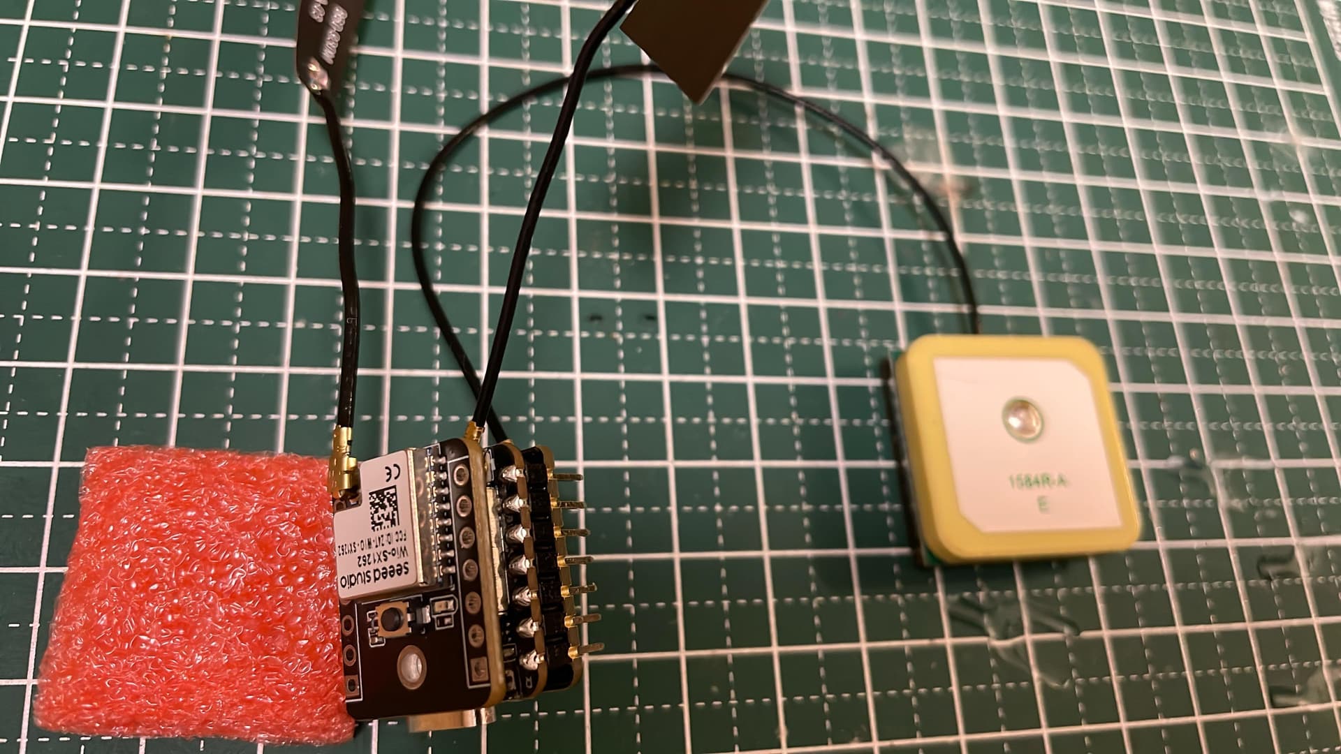
So, this kit seems somewhat superior to a Heltec rig, based on my experience in the field and home.
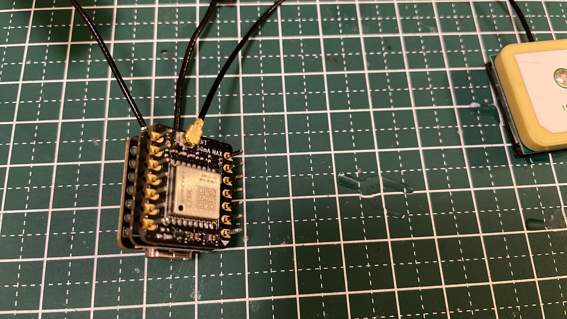
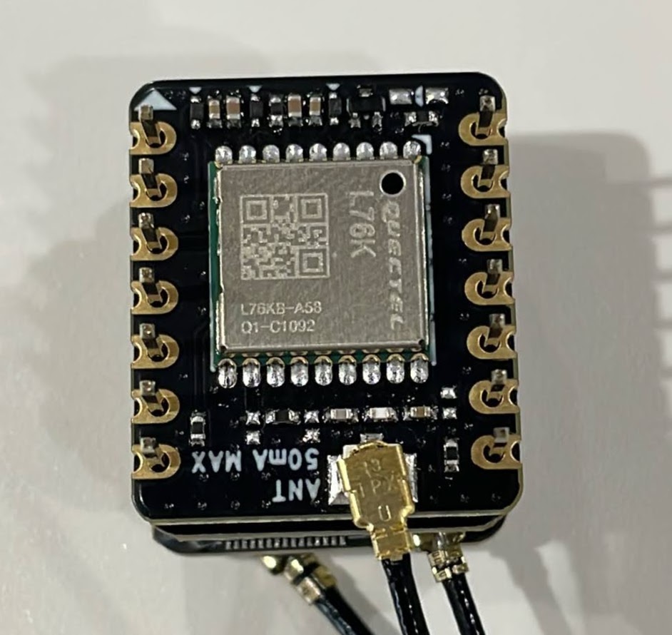
One problem though. Even though disabled in M3shtastic, an attached L76K GNSS module is constantly kicking out a TELEMETRY_APP onto the local mesh, every thirty seconds. Pretty annoying.
Some details elude me in re powering and the L76. Any pointers would be appreciated.
Hello, thank you for the post. I learn a lot from you.
I am fabricating a node for Meshtastic. I have a problem with my battery.
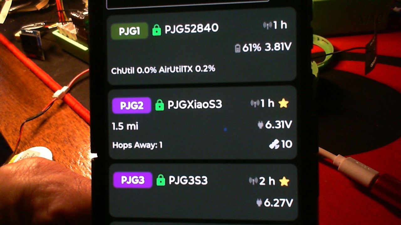
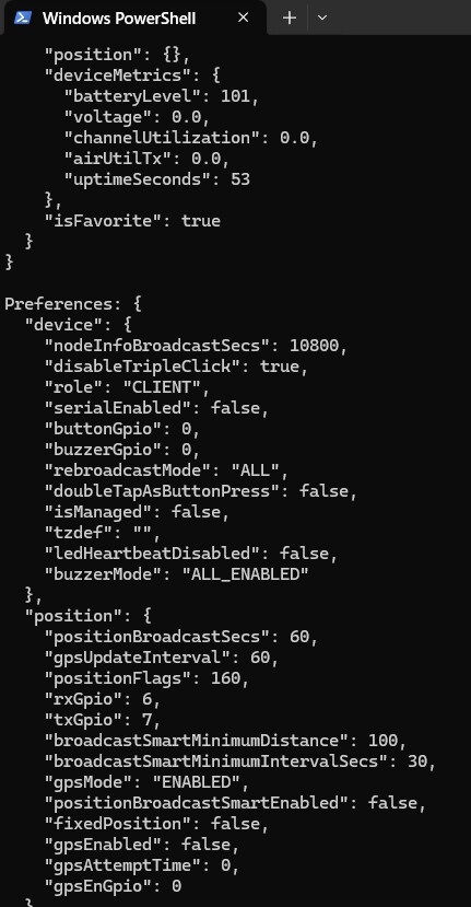
I soldered at the 2 recommended points under the esp32s3 board for the battery, and it works well for power and charging with USB is also fine, but in the Meshtastic app, it always shows 0.00 V and the plugged-in icon.
The firmware I am using is 2.6.10.9ce4455 Beta for XIAO ESP32S3 and Wio-SX1262.
What could be the problem?
Thank you.
The XIAO has no voltage sensing capability… this is frustrating… I do not know how to solve the problem
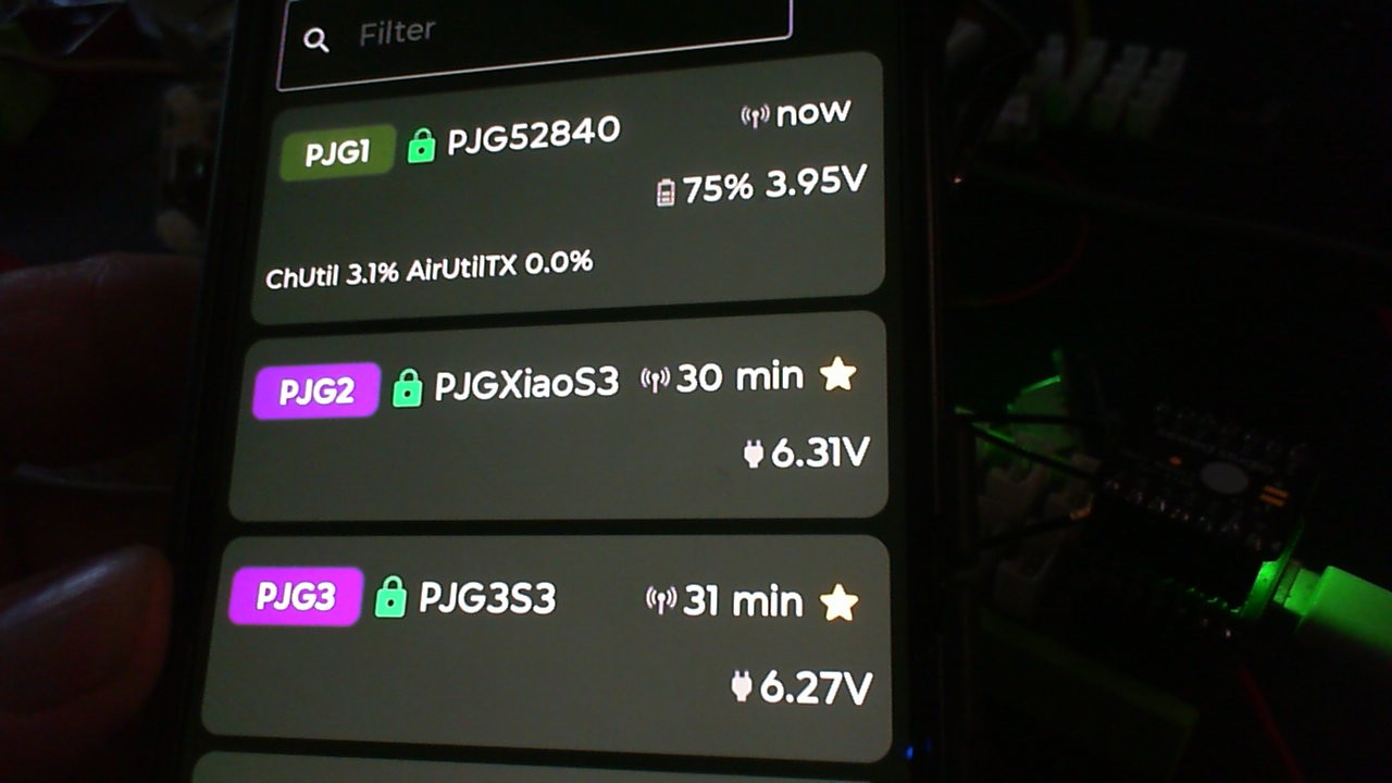
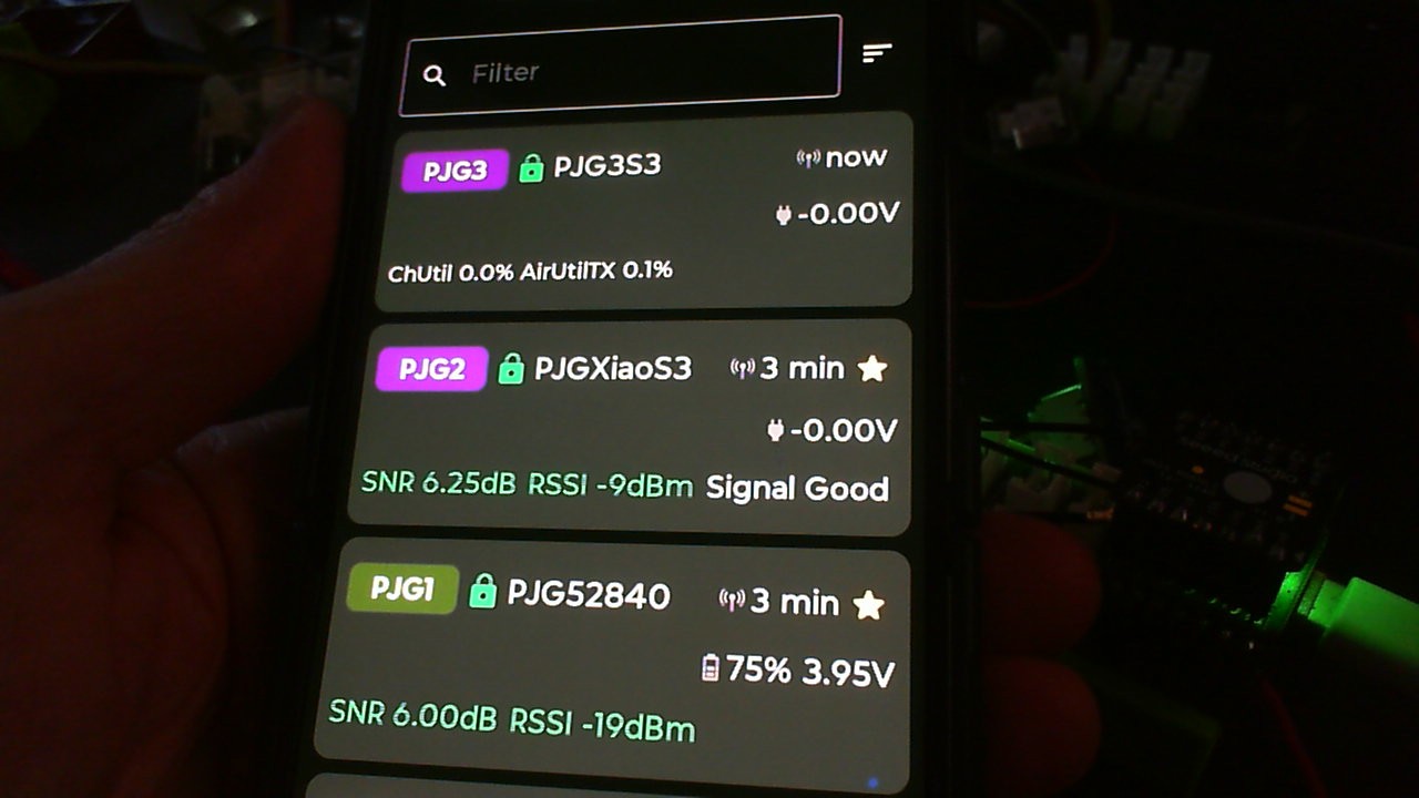
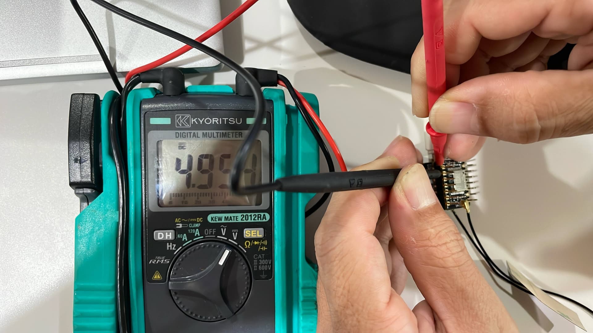
It’s like second image
I have changed the firmware several times, I have left it for several days but still the same problem persists. Right now I am resetting it to factory settings to test.


check your solder joints
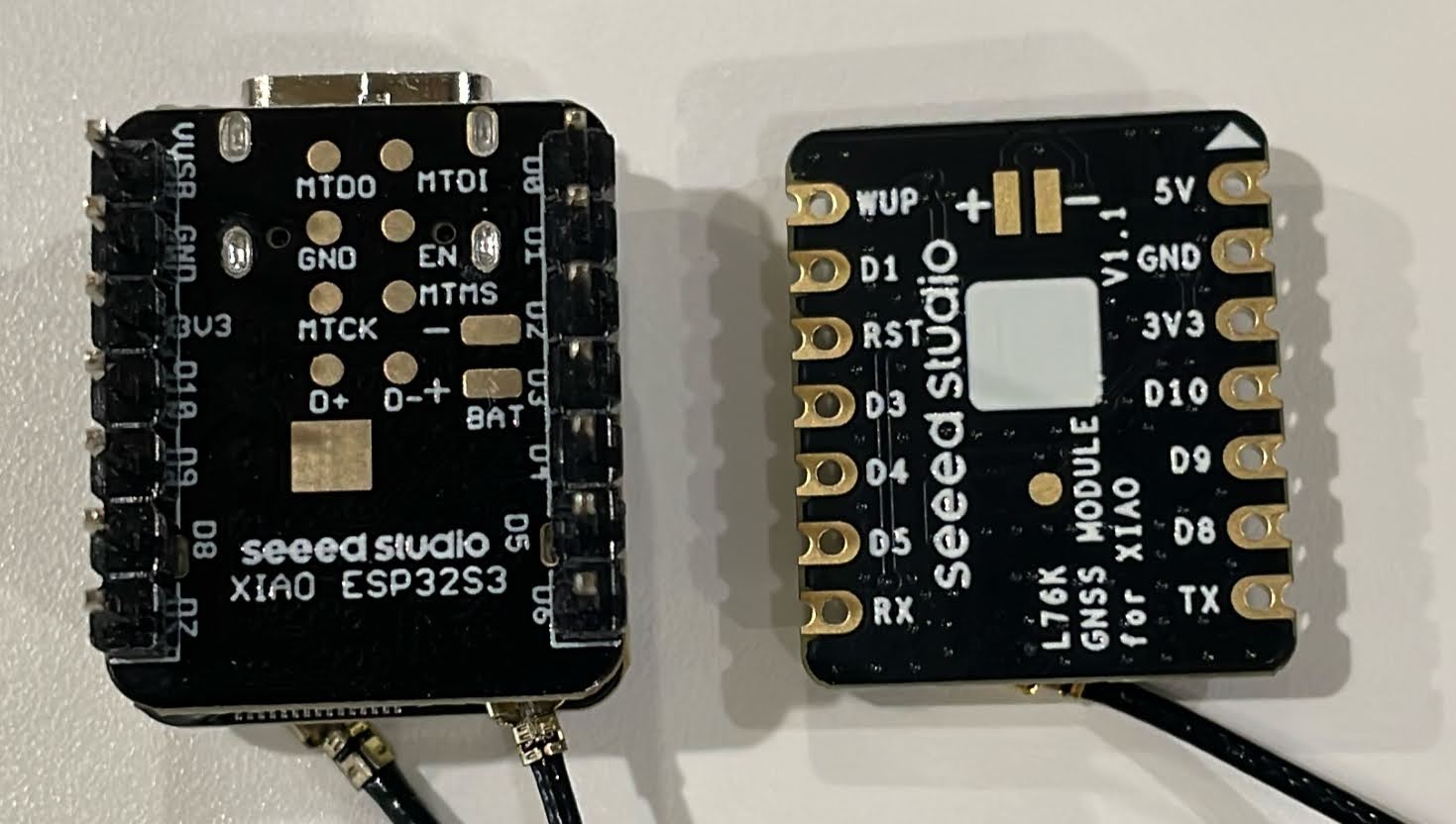
i think you may have it installed up side down
make sure the upper right corner is the 5V GND and 3V3 pins aligned
actually I think they had a problem that some of the pins were not compatable with multiple sandwitch… i an sending it to my guy
it is still hard to say… i am not trying to be difficult the ground pin should mate to the ground pin… 3v3 and one board call it 5 the other says VUSB or someting… I have some seeed engineers checking into it as well
I am sure you understand you have to solder the pins
Hi itaru, a small arrow on the edge of the PCBA indicates the orientation of the Type-C interface after assembly. You can align the module according to this arrow. Your connection is correct.
I have no idea what to test or how to proceed anymore.
(Since even new boards can be defective, I test them before soldering.)
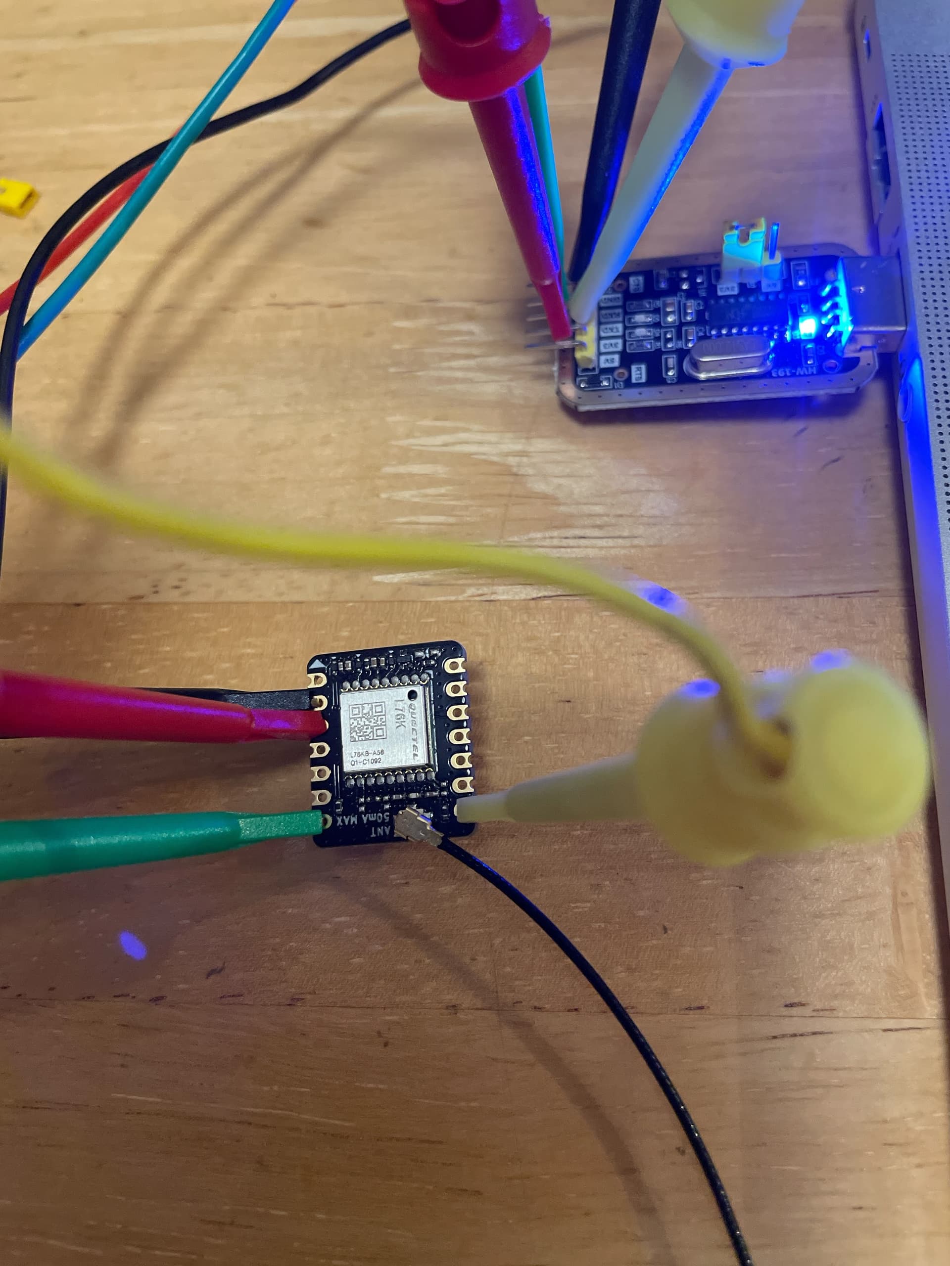
I purchased a USB to TTL converter and tried it out.
Does not work
USB Jumper Pin 3.3V
USB– 5V → L76K - 5V
USB– GND → L76K - GND
USB– TXD → L76K - RXD
USB– RXD → L76K - TXD
L76K-GND <-0.3V-> L76K-3.3V
LED does not light up
Satellite received!
USB jumper pin 3.3V
USB– 3.3V → L76K - 3.3V
USB– GND → L76K - GND
USB– TXD → L76K - RXD
USB– RXD → L76K - TXD
LED does not light up
Without disconnecting the L76K connector
Does not work
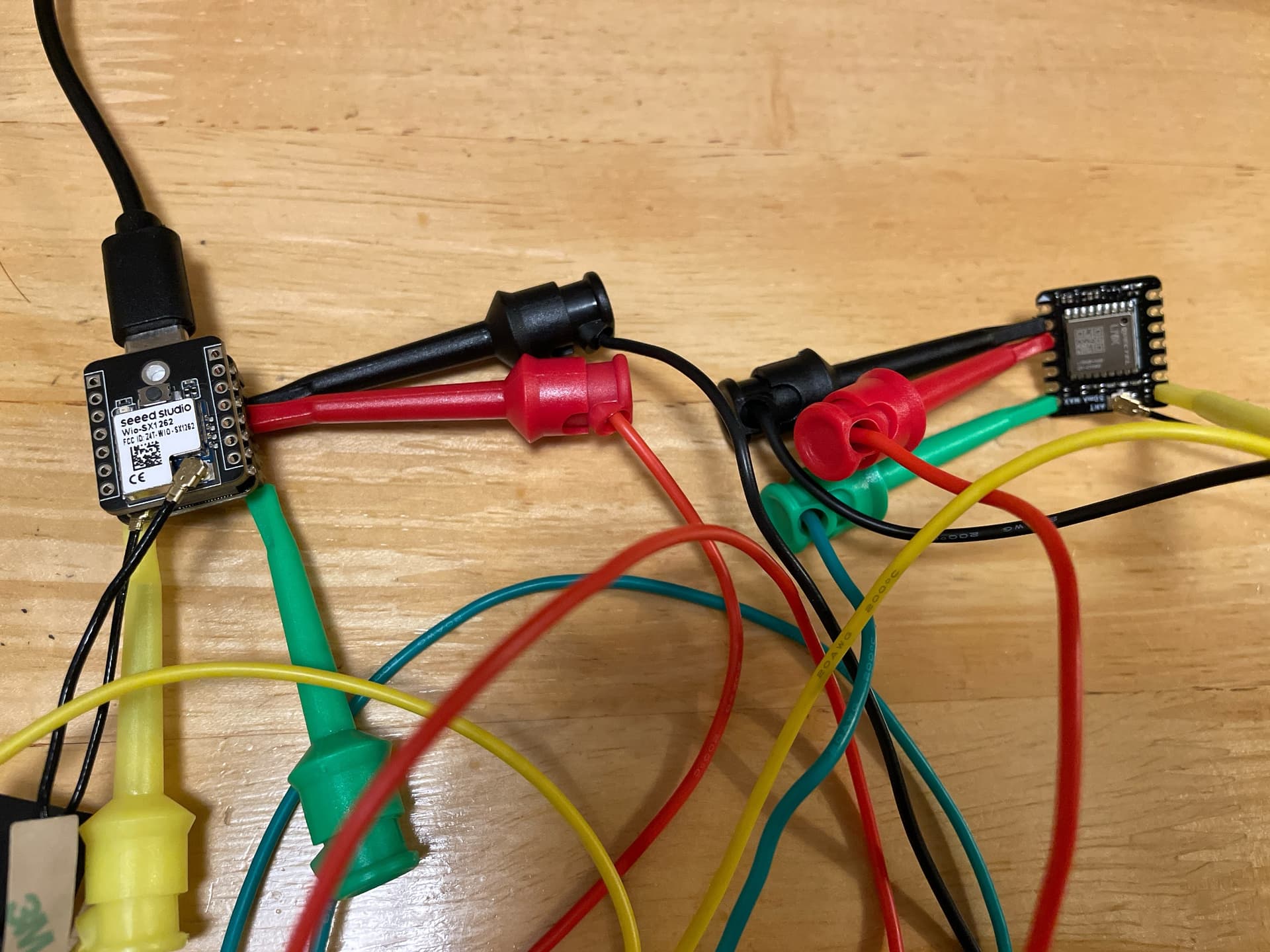
ESP32S3-3.3V → L76K - 3.3V
ESP32S3– GND → L76K - GND
ESP32S3– D6 → L76K - RXD
ESP32S3– D7 → L76K - TXD
LED does not light up
GPS is not recognized
Satellite received!
Does not work
Hi David,
I know it’s connected correctly.
I think even the minimum connections are right.
But it just won’t recognize it.
The L75K’s LED won’t light up.
I don’t even know how to check it with Meshtastic.
can you see a version number on it?

did you bring the wakup pin high to wakeup?
did you bring the reset pin high to normal?
also you should connect 3v3 and ground and not 5v and pull up pins to 3v3… not sure if it is 5v compliant
new version does not have an indicator led to save power
Note Change Record
2024/12/6, Fix the RST pin from D10 to D2.
2025/3/31, Remove the fix status indicator
Thank you.
I didn’t know the new version didn’t have LEDs.
I haven’t tried wake up or reset.
That’s because it says to just connect it.
So, I simply connected the four wires and confirmed serial communication started.
That means just connecting it isn’t enough; I think it might be a Meshtastic configuration issue.
I tried three patterns for the Meshtastic firmware: factory default, static, and the latest version.
meshtastic is definatly a different animal… you should be able to use arduino tinygps+ to read the sandwitch of the XIAO
After configuring meshtastic, it suddenly recognized the GPS.
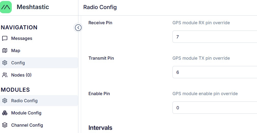
I had to change the settings in meshtastic for device postion precision in channel, usePreset region in lora, GPS.
Even while recognizing GPS,
“gpsEnabled”: false
remained unchanged—a mystery.
Thank you for everything.
Now I can move forward.