Do you think the XIAO_C5’s load switch TPS22916 is turned on?
How do you think power is supplied from the expansion board to the XIAO_C5?
Hi There,
Here is how I see the power delivery and why it’s working:
-
Power Path from Expansion Board:
- When unplugged, the Expansion Board draws from the LiPo cell connected to its JST port. Its power path feeds both the battery rail and powers the board’s 3V3 rail directly through the header pins to the XIAO_C5.
-
The TPS22916 State:
- If the battery is present, the switch’s
ONpin is already satisfied/pulled high via the battery power circuit (or the 3.3V rail is being supplied directly from the carrier board’s regulator), so the C5 receives stable VDD.
- If the battery is present, the switch’s
-
The Proof:
-
As you can see in my photos with the timestamps, the board boots, runs, and stays active on battery alone for 15+ minutes with zero drops.(still running as we speak)
-
The initial lockup everyone was experiencing wasn’t a dropped power rail—it was the software stalling in the
USB CDC On Bootserial handshake when USB detached. With CDC disabled, the power-up sequence and Wi-Fi scanning complete smoothly every time on pure battery.
-
HTH
GL  PJ

I am examining the circuit diagram in detail.
- To turn on the load switch TPS22916, a voltage must be present at +3V3.
- +3V3 is generated from VSYS.
- VSYS is selected from either VBUS or VBAT by the TPS2116 power supply multiplexer.
- However, the expansion board is only supplying 3.3V to +3V3_OUT; it is not supplying anything to either VBUS (USB) or VBAT (battery pad).
I’m puzzled as to why the load switch is ON.
It looks like I’ll need to get my hands on C5 to figure this out.
EDIT:
I figured that the 3.3V signal, which loops through the I/O and I2C pins from the expansion board, pulls up the internal 3.3V line on the XIAO, turning the load switch ON, and after that, power is supplied via the load switch.
YOU  are the Ninja


Battery is on expansion board’s JST connector and NOT in backwards.
Battery is already fully charged to 4.1V.
The answer is No, and by the schematic, it should Not work. So …my bad from the git-go.
I’m only posting this for others to have a factual account that a XIAO ESP32C5 has a different power path and it will not operate from the battery power on the XIAO Expansion Board nor the XIAO Round Display. If you want a hard switch, you’ll have to put it inline and connect to battery pads on the bottom of the C5 module. Otherwise, use sleep mode.
what are the wires going under connect to?
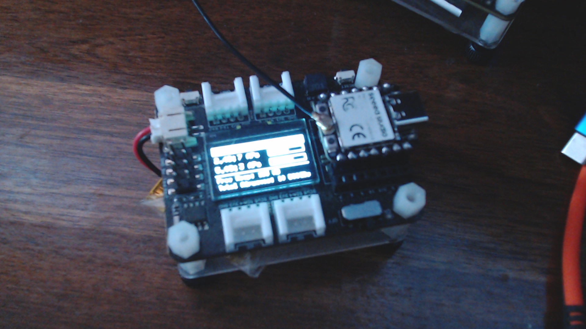
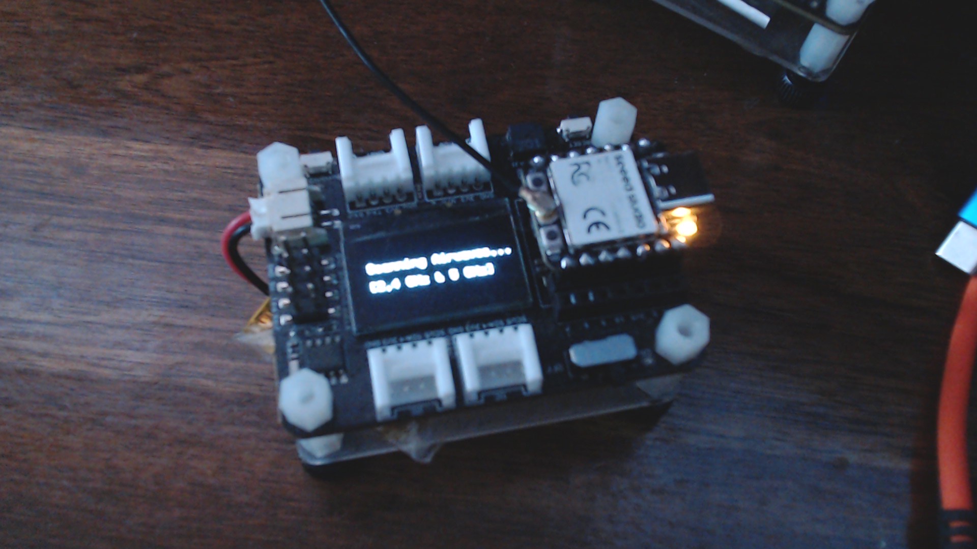
Hi there,
And…So, Please Don’t besmirch my Round Display .
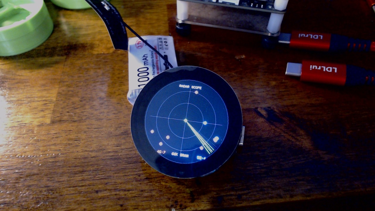
or
https://vimeo.com/1238894147?fl=pl&fe=sh
HTH
GL PJ
Built with, Both CDC boot and PsRam disabled in tools…
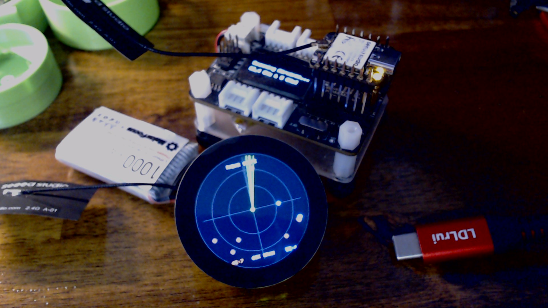
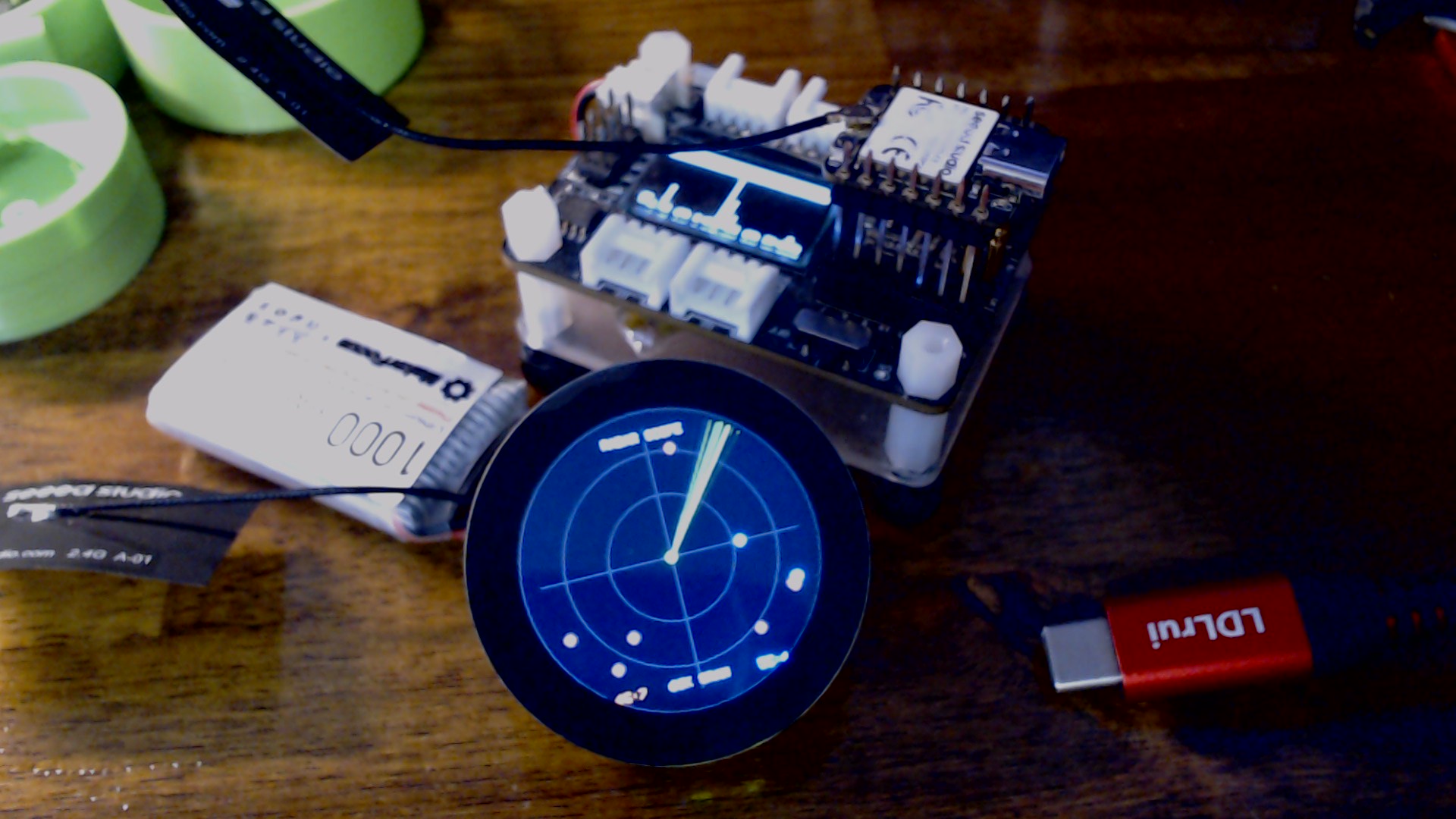
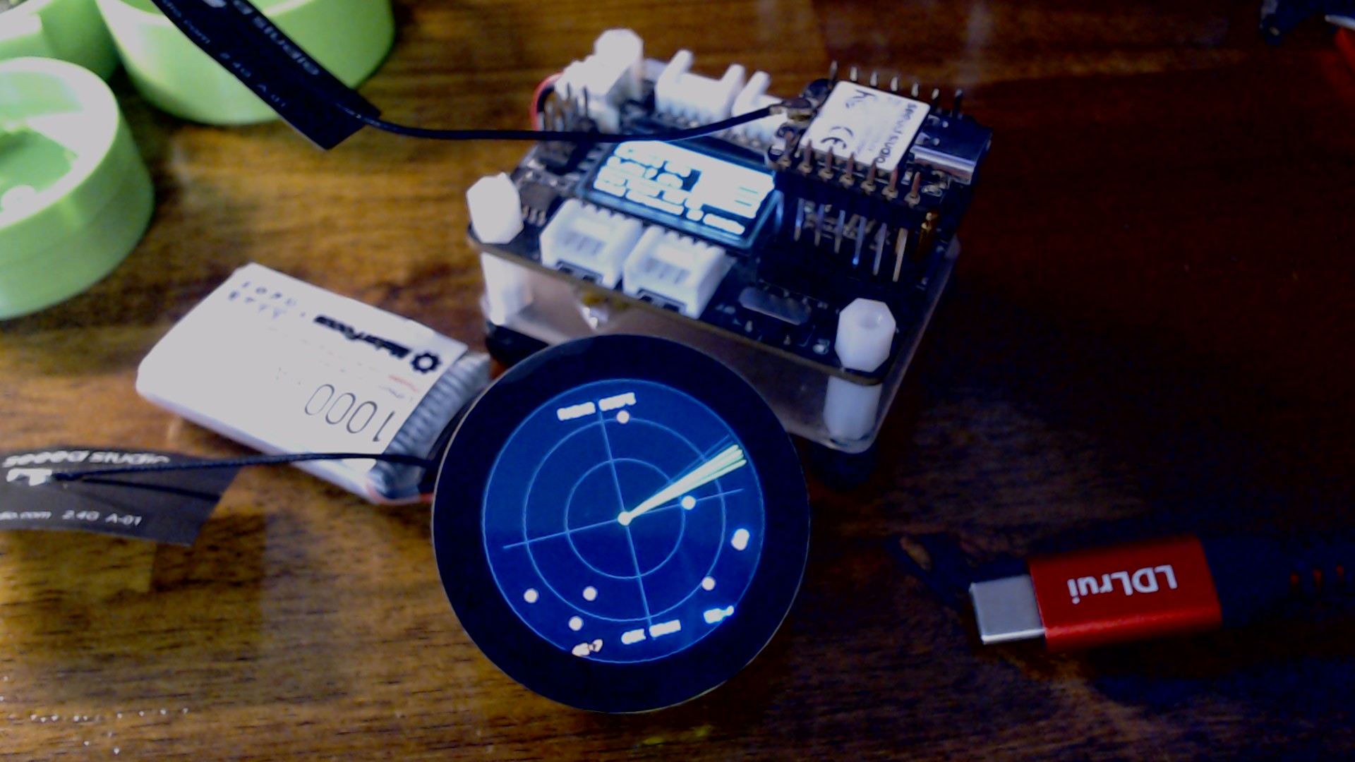
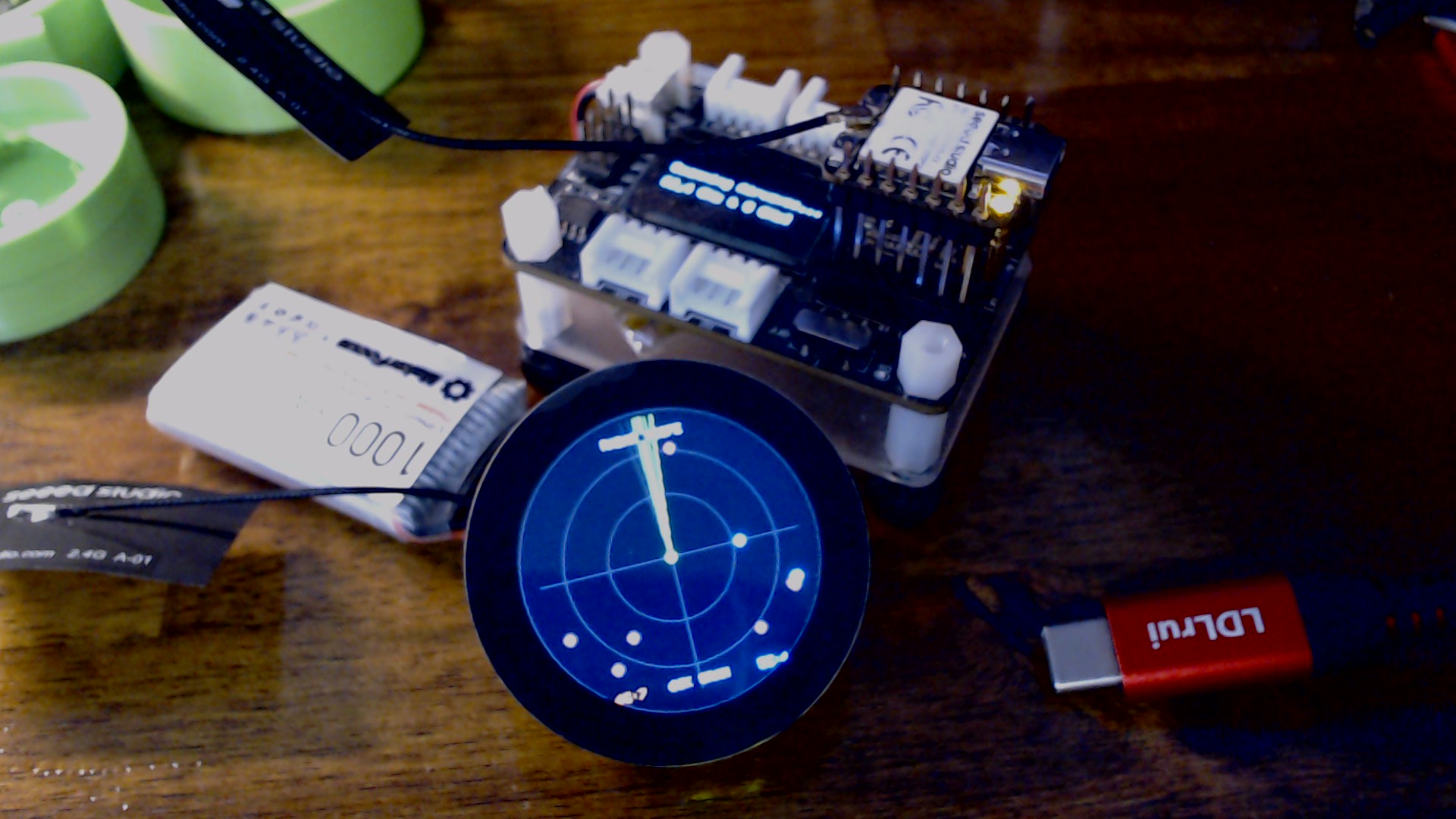
Batteries Included… 
apologies for the Potato like Camera photos…
TI engineers have confirmed that while the load switch has a back-current prevention circuit, it does not function at currents below IRCB=500 mA. Therefore, once the load switch is turned ON, it appears that 3.3 V will be supplied to the XIAO from the 3V3_OUT pin.
Here is my hypothesis.
On the expansion board, three SPI lines—pulled up with a 4.7k resistor to the 3.3V generated by the JST battery—are connected to the XIAO. The 3.3V passes through the ESD protection diodes on the XIAO’s ports and energizes the internal 3.3V lines within the XIAO.
If the current consumption inside the XIAO is low, the voltage drop across the 4.7k resistor and the diode will also be small, and the load switch’s EN pin will reach Vih=1V or higher, turning it ON.
If the current consumption inside the XIAO is high, the voltage drop will also be large, and the EN pin will not reach Vih=1V or higher, so the load switch will not turn ON.
In other words, whether the load switch turns ON depends on the magnitude of the current consumption during power-on and XIAO initialization.
https://e2e.ti.com/support/power-management-group/power-management/f/power-management-forum/1267955/tps22916-tps22916cn
Hi @jrgert,
What happens if you turn on the expansion board’s power switch while resetting the XIAO_C5?
Hi there,
So , for anyone keeping Score

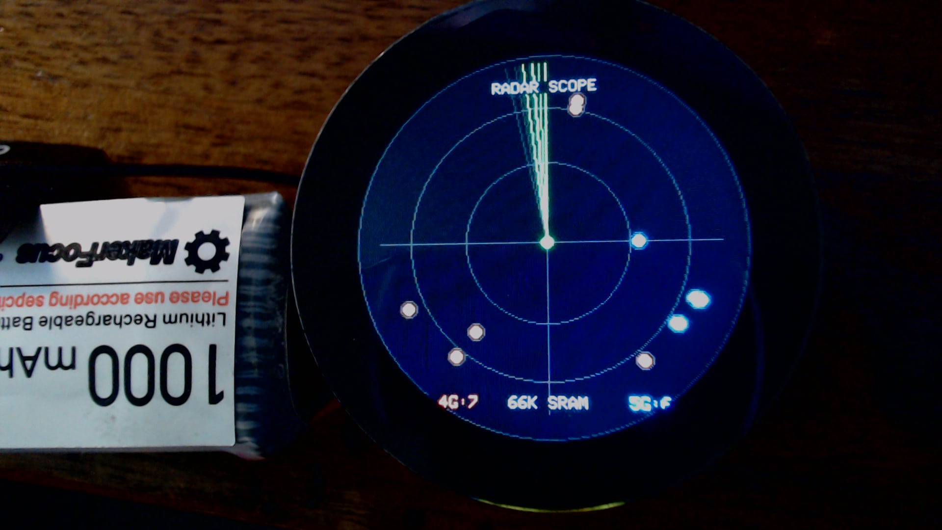
HTH
GL PJ
CDC-BOOT Disabled is FIX…
I have 3 Expansion boards, 2 Round displays, (5) C5’s 3, I purchased and two Seeed sent original eval units, There is NO problems with that MCU, other than the dual bands require JUICE a lot of it. PERIOD.

Hi there…
So, here is the technical explanation for those who asked, I checked with Seeed & Expressif, & FWIW it is how it works.
The Software Trap: What “USB CDC On Boot” Actually Does
On modern ESP32 chips with native USB (ESP32-S3, C3, C6, C5), the silicon does not use an external USB-to-UART bridge chip (like a CP2102 or CH340). Instead, the microcontroller has an internal USB Serial/JTAG controller peripheral built directly onto the die.
When you compile in the Arduino IDE with:
Tools -> USB CDC On Boot: "Enabled"
the compiler passes the build flag -DARDUINO_USB_CDC_ON_BOOT=1.
Under the hood, before your setup() function is ever reached, the ESP32 core runtime calls an early startup constructor (initArduino()). Because that flag is set to 1, the runtime executes:
Serial.begin(); // Initializes the native USB CDC peripheral as the default hardware console
It binds Serial directly to the chip’s internal USB CDC endpoint rather than a physical UART pin.
Why Untethered Battery Boot Causes a Deadlock
When the MCU boots on a LiPo battery with no USB cable connected to a host computer:
1. The Missing Enumeration & Ring Buffer Saturation
USB CDC is a negotiated bus protocol. An endpoint needs a host (PC/Mac) to supply $V_{\text{BUS}}$, perform USB bus enumeration, set up IN/OUT packet pipes, and service interrupts.
On pure battery:
-
There is no host to send USB
SOF(Start-of-Frame) packets. -
There is no host pulling data packets out of the hardware FIFO.
-
The internal USB Serial TX ring buffer (typically 64 to 256 bytes) fills up almost instantly on the very first few log lines or boot messages (
Serial.printor early ESP-IDF core system prints).
2. The Blocking Write Call
In traditional UART, if no cable is plugged in, the UART FIFO just shifts bits out into empty air on the TX pin and discards them; the CPU never waits.
In native USB CDC drivers, if the internal buffer is full because no USB host is reading from it, the low-level write function:
esp_vfs_dev_usb_serial_jtag_write(...)
enters a blocking wait loop (or yields to a FreeRTOS task that never resolves). The driver assumes: “A USB connection exists, so wait until the host clears the buffer before returning.”
If no host ever connects, the timeout either lasts several seconds per character or locks up indefinitely. If setup() or your libraries contain even a single Serial.print() statement, the MCU halts permanently right at that line.
3. The while (!Serial) Trap
Even if the driver doesn’t hang inside the ring buffer, many sketches include the standard idiom:
Serial.begin(115200);
while (!Serial); // Wait for terminal connection
When USB CDC is enabled, the expression (!Serial) evaluates the DTR (Data Terminal Ready) or RTS (Request to Send) control line signal from the PC host. On battery, DTR never asserts true. The program becomes trapped in an infinite while loop before setup() can complete, leaving displays blank, radios uninitialized, and peripherals off.
Why People Misdiagnose It as a “Hardware/Power Defect”
When a developer unplugs their board from USB and plugs in a 3.7V LiPo:
-
The 3.3V rail measures rock-solid with a multimeter.
-
The onboard power LEDs or charging status lights are active.
-
The display or sensors remain completely dead.
Because it runs fine on the PC but appears completely dead on a battery, the instinctive conclusion is: “The carrier board has a power gating issue, a blown LDO, or needs an external diode mod to fool the power path.” 


In reality, the hardware power tree is working as intended—the CPU is executing instructions, but it is halted inside a software spinlock waiting for a host terminal packet that will never arrive.
What Setting It to “Disabled” Fixes
When you set:
Tools -> USB CDC On Boot: "Disabled"
-
The runtime skips auto-binding the console to native USB CDC at power-on.
-
Early boot logs are directed to the internal hardware UART, which shifts data out into open silicon without waiting for an ACK or handshake.
-
Your sketch immediately executes
setup(), initializes SPI/I2C buses, powers up the display, and entersloop()without ever looking for a USB host.
NOW, YOU KNOW
and BTW, just tried to order 2 more Round one’s BACK order.. worth the wait.