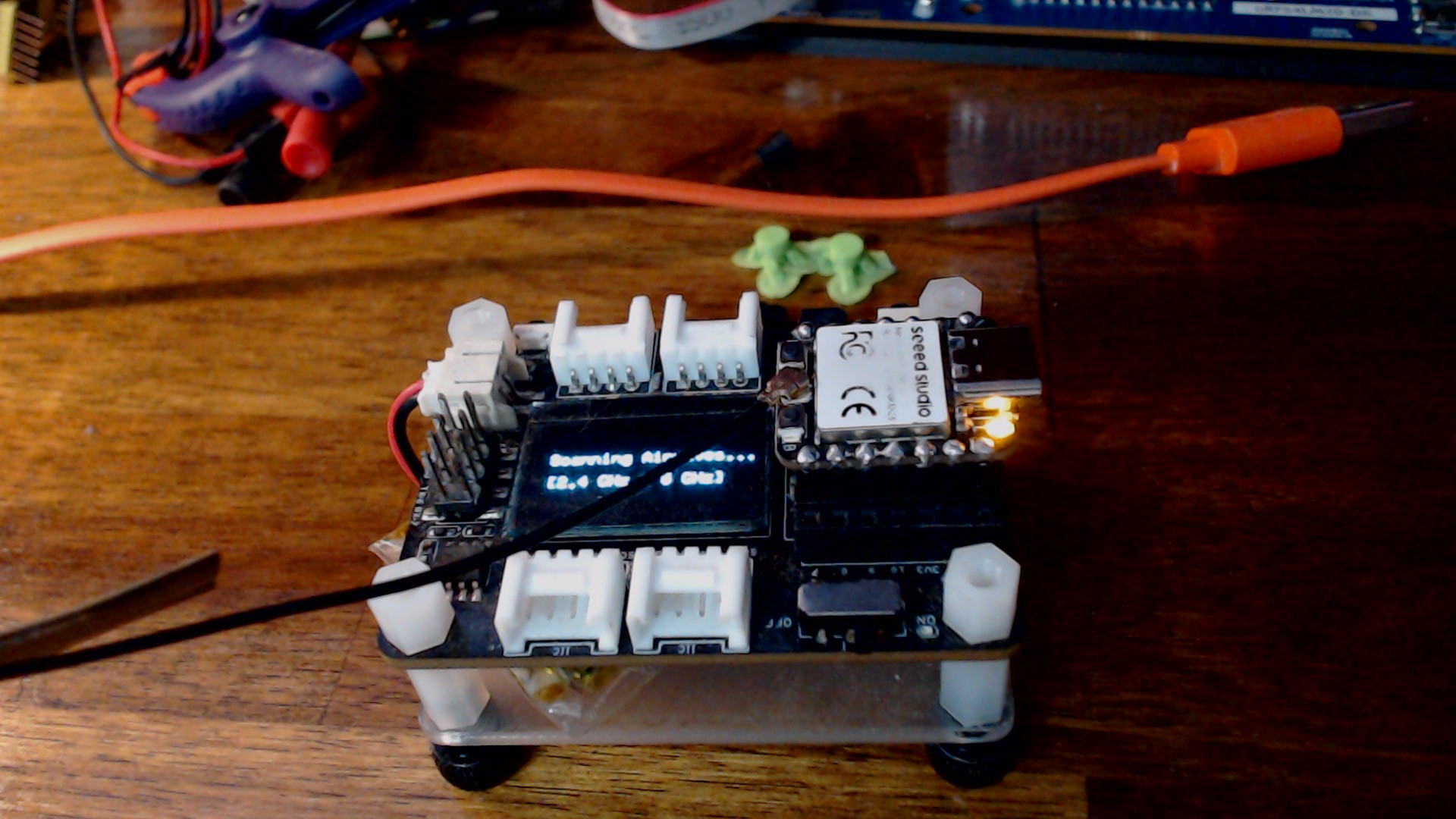
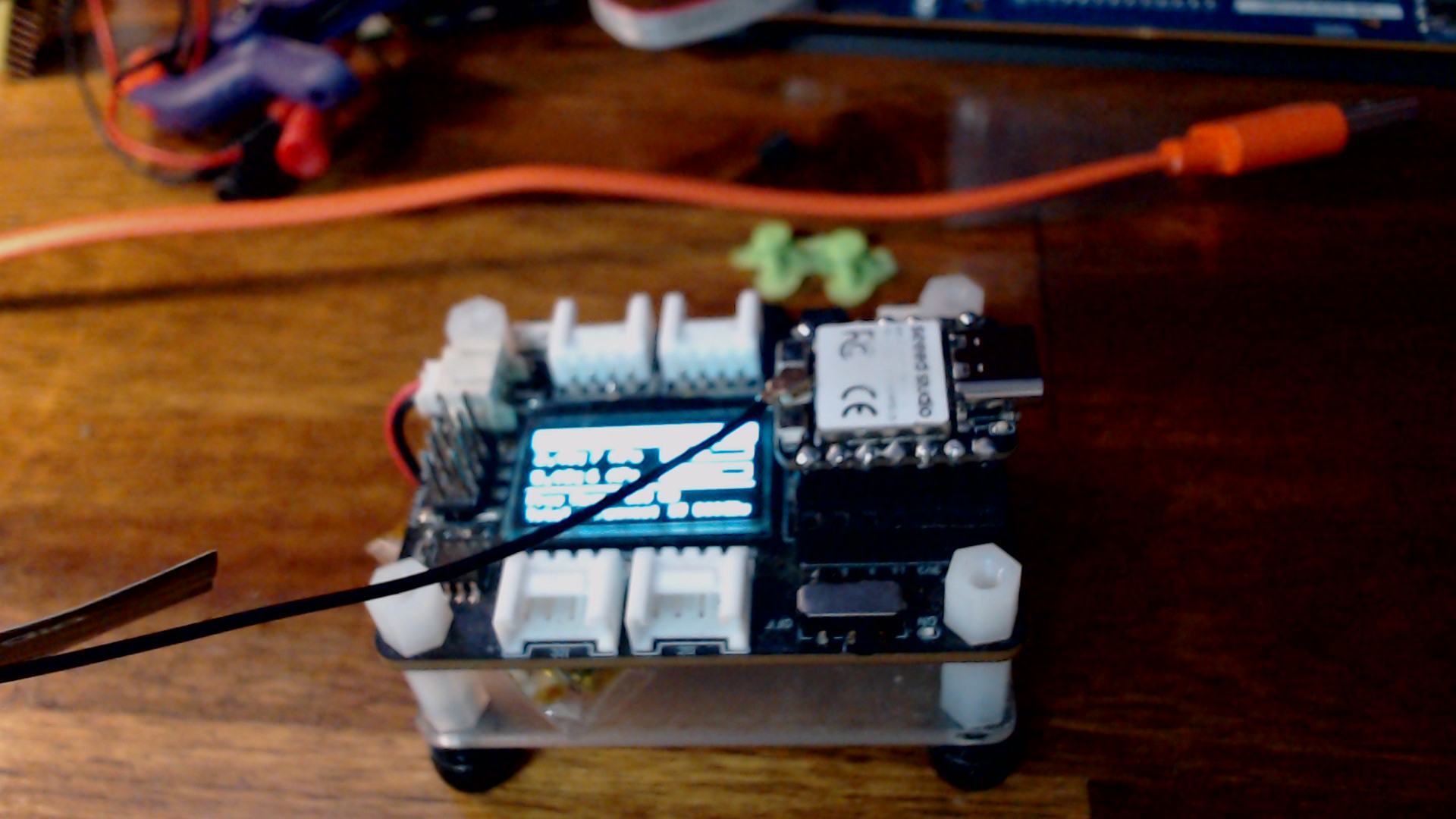
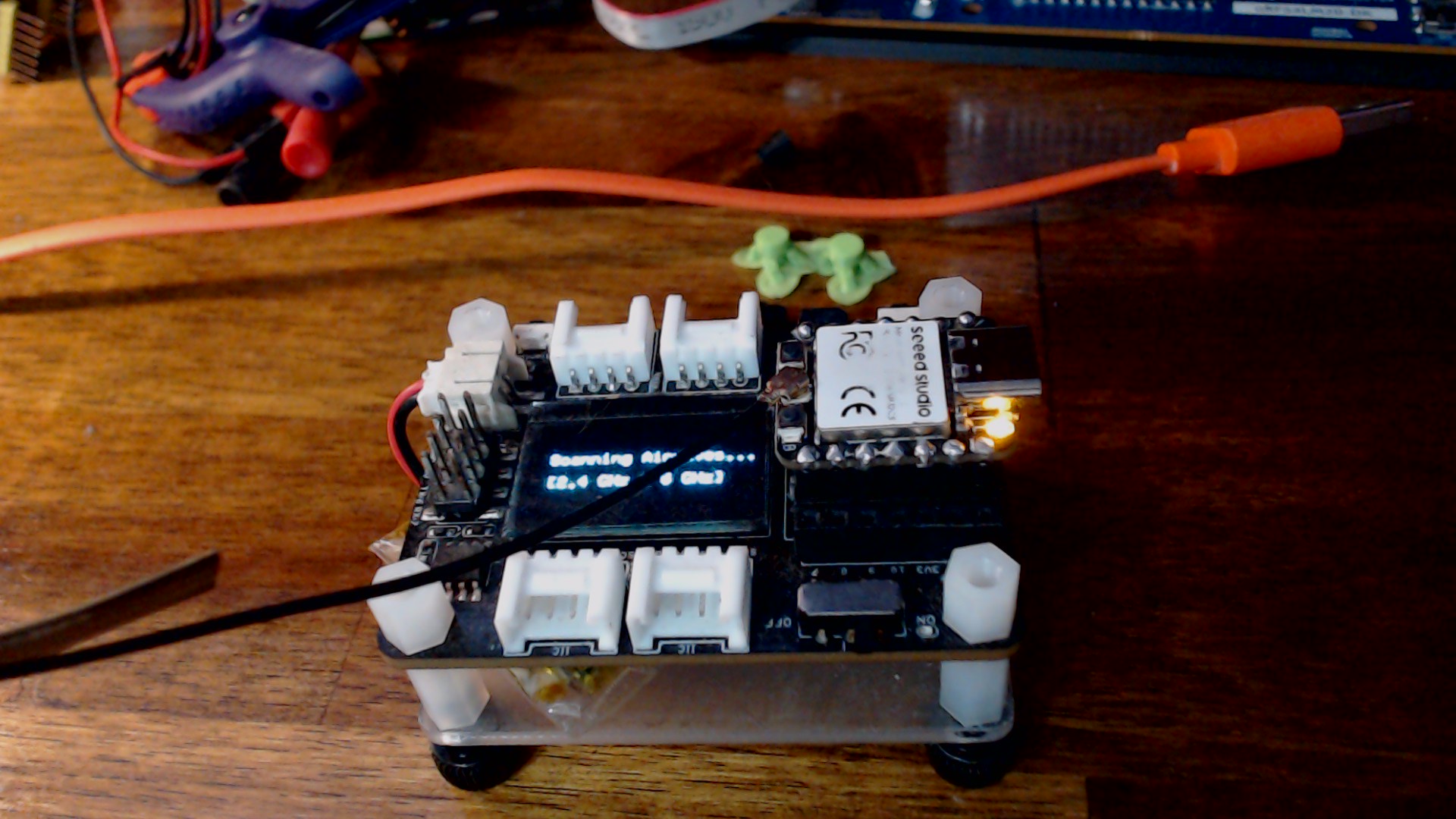
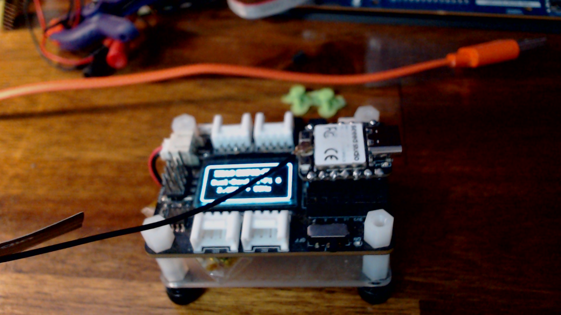
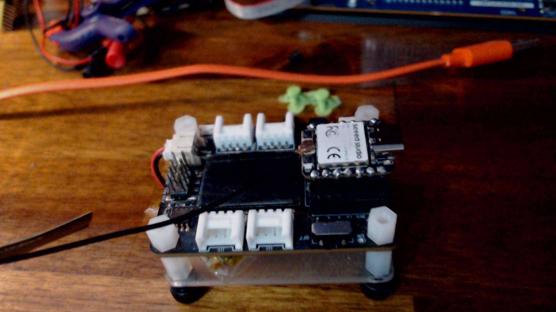
Xiao-esp32c5 will not run without usb power

I was going to click Solution, but it’s really not. In fact, really disappointing.

Here’s how the Expansion Board plays with a diode from 3V3 to USB5V on the ESP32C5.

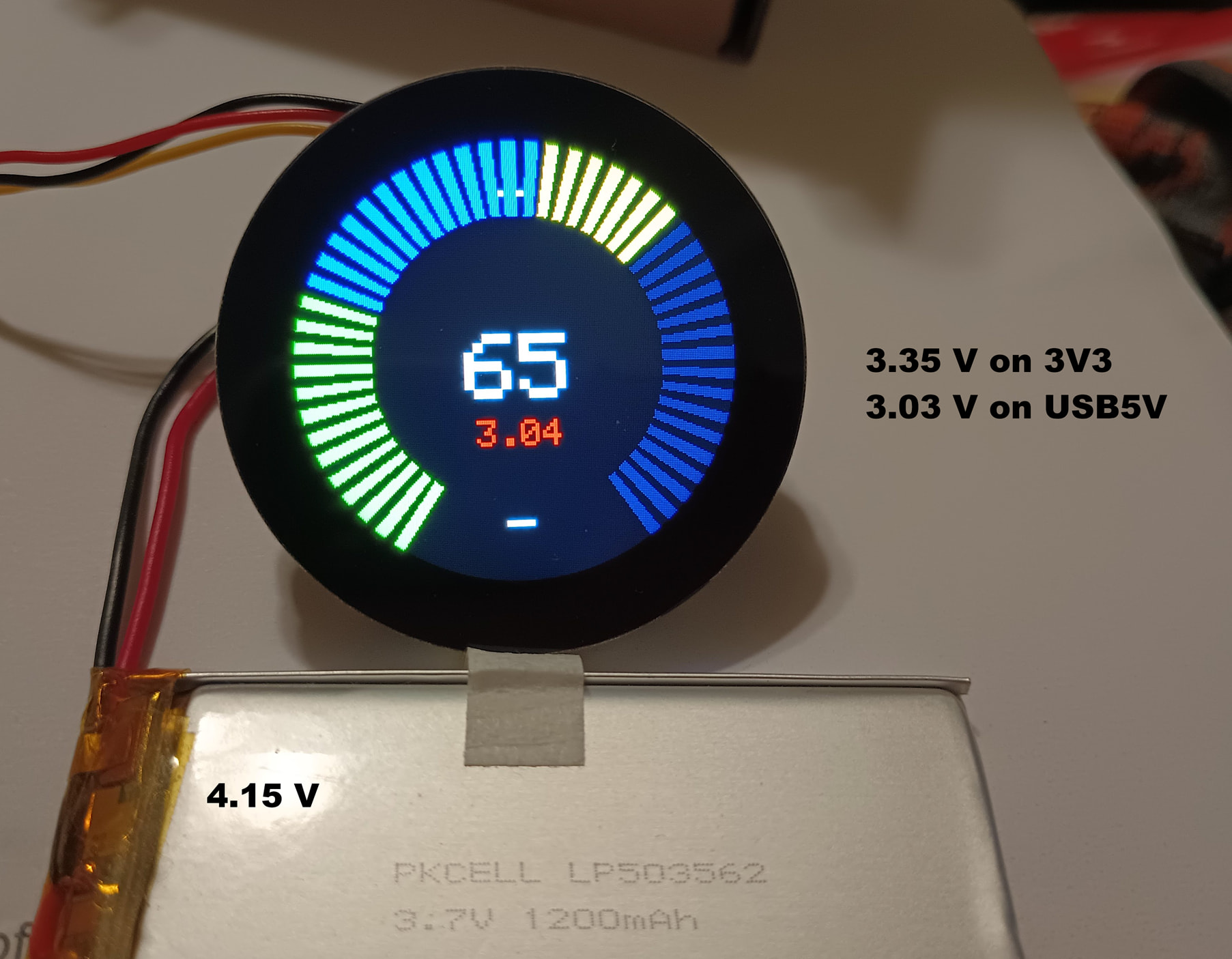
Here’s how the Round Display plays with a diode from 3V3 to USB5V on the ESP32C5.
NOTE: It only starts running on USB power. Pull USB power, power switch off and power switch on and …Nothin’!!
It won’t start via battery on the Round Display board.

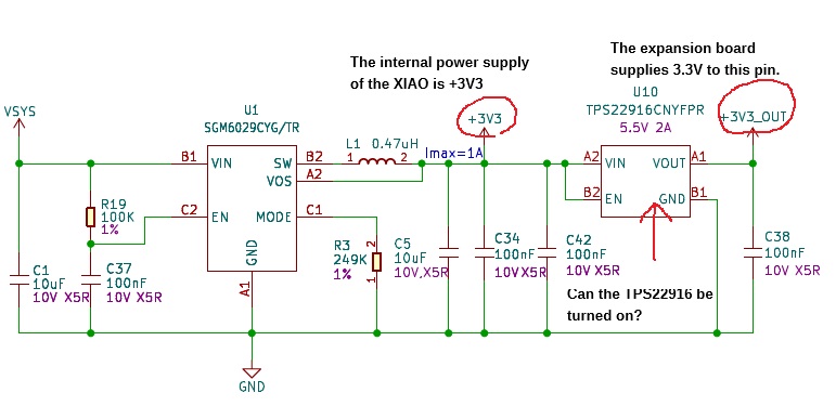
The minimum operating voltage for the ESP32C5 is 3.0V. Even if you apply 3.03V to the USB5V pin, it is highly likely that the SGM6029 will not be able to generate a 3V output.
Please check the circuit diagram and datasheet.

Hi there,

So sometimes WE overthink it…

That in mind, I looked into this a little closer here, And I’m able to reproduce the same issue I think you had originally.

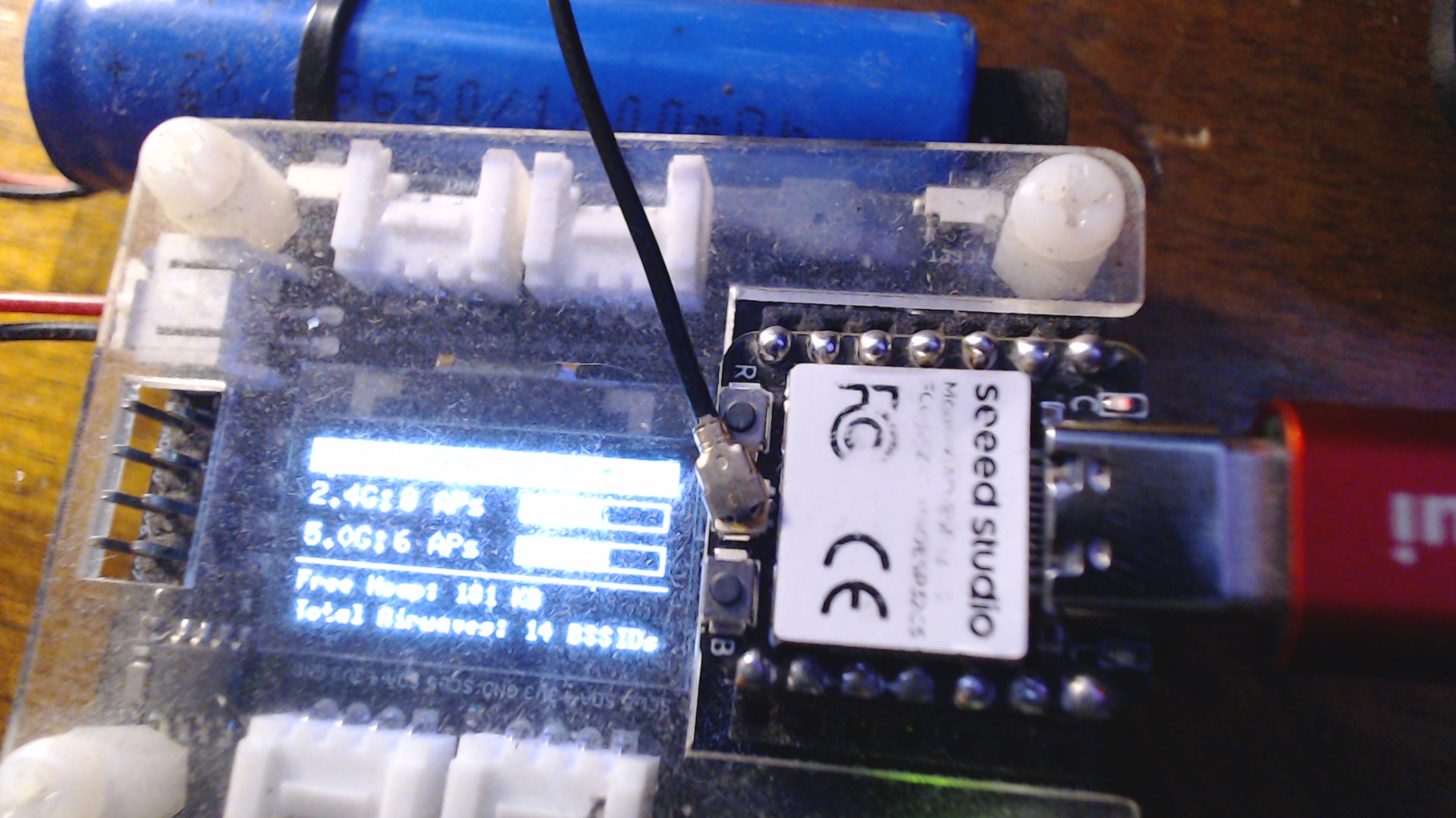
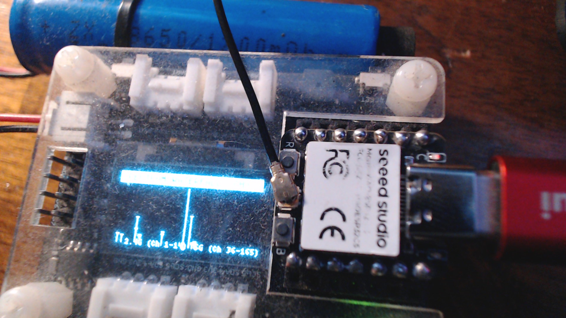
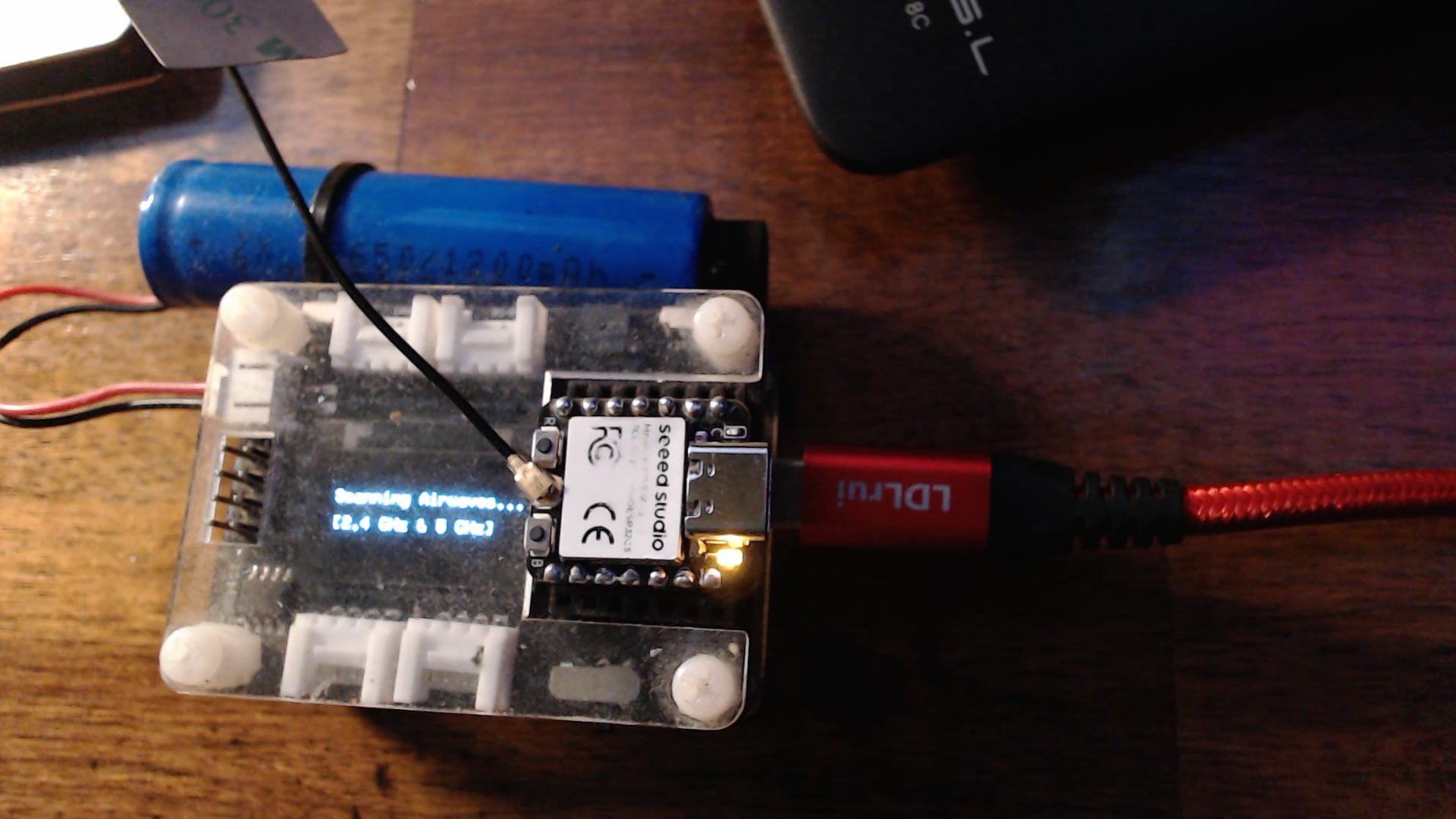
Humor me and Load this Code and Tell me it runs It is more than blinking the LED and will test the C5 when you have USB connected and the WiFi see’s both 2.4 and 5Ghz. and it displays how many AP’s on both bands it see’s. it cycles and works? YES ?
Test_C5_sketch_oct21a.zip (1.8 KB)

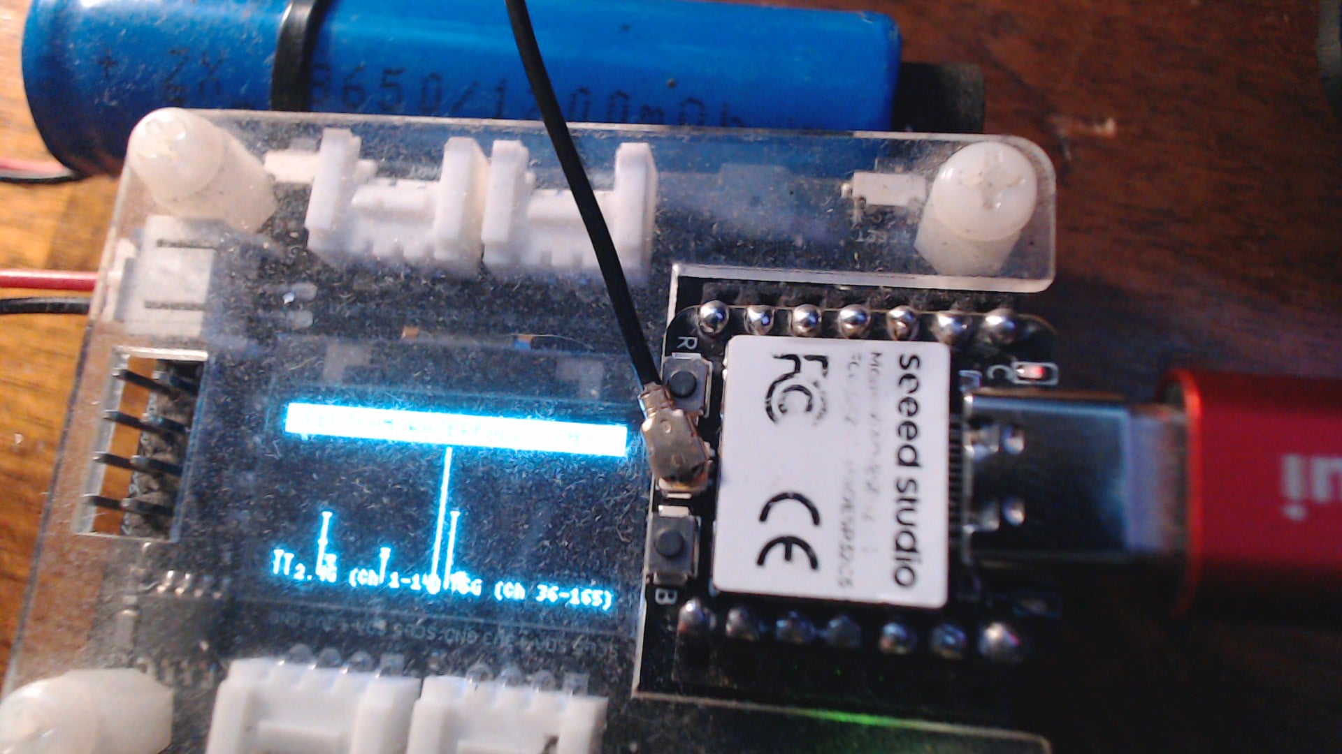
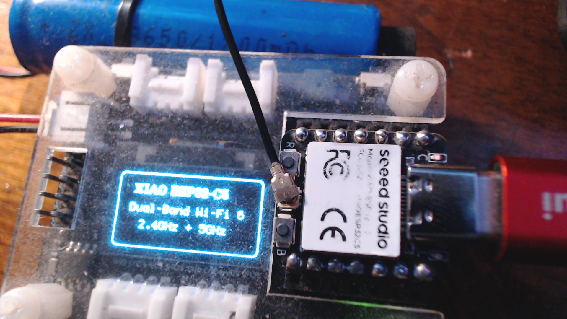
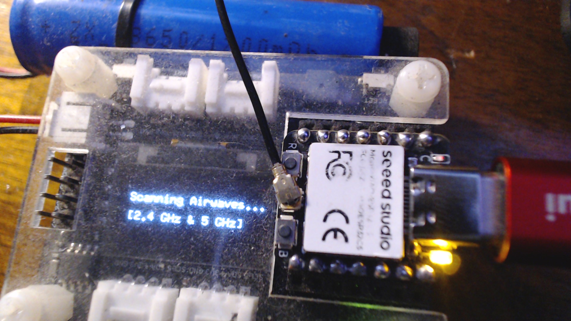
You get these screens…

ONE


TWO

THREE

FOUR

YES/ NO ?

Now unplug the USB. does it stall and stop at main screen or when you reset it stalls, blinks , tries but nada..

YES ? True ?
Test_C5_sketch_oct21a.zip (1.8 KB)

// ==============================================================================
//  PROJECT:   XIAO ESP32-C5 Dual-Band Spectrum & Signal Analyzer
//  AUTHOR:    PJ (SmartIPTech) & Gemini AI Co-Pilot
//  HARDWARE:  Seeed Studio XIAO ESP32-C5 on XIAO Expansion Board (SSD1306 OLED)
//  FEATURES:  Simultaneous 2.4GHz + 5GHz Wi-Fi 6 Sniffing, Peak RSSI, & Live Waterfall
//  NOTE:      Runs untethered on battery 
// If PJ Glasso , tells you the secret. :grin:
// ==============================================================================
#include <Arduino.h>
#include <Wire.h>
#include <U8g2lib.h>
#include "WiFi.h"
#include "esp_wifi.h"

// Hardware I2C for XIAO Expansion Board OLED (SSD1306 128x64)
U8G2_SSD1306_128X64_NONAME_F_HW_I2C u8g2(U8G2_R2, /* reset=*/ U8X8_PIN_NONE, /* clock=*/ SCL, /* data=*/ SDA);

void setup() {
  pinMode(LED_BUILTIN, OUTPUT);
  digitalWrite(LED_BUILTIN, HIGH); // Off initially

  u8g2.begin();

  // Intro Splash
  u8g2.clearBuffer();
  u8g2.setFont(u8g2_font_ncenB08_tr);
  u8g2.drawRFrame(0, 0, 128, 64, 4);
  u8g2.drawStr(14, 18, "XIAO ESP32-C5");
  u8g2.setFont(u8g2_font_profont11_tr);
  u8g2.drawStr(12, 34, "Dual-Band Wi-Fi 6");
  u8g2.drawStr(22, 48, "2.4GHz + 5GHz");
  u8g2.sendBuffer();
  delay(2000);

  // Set Wi-Fi to Station mode
  WiFi.mode(WIFI_STA);
  WiFi.disconnect();
  delay(100);
}

void loop() {
  // Activity LED blinks while scanning
  digitalWrite(LED_BUILTIN, LOW);

  // Status Screen during scan
  u8g2.clearBuffer();
  u8g2.setFont(u8g2_font_6x10_tr);
  u8g2.drawStr(10, 24, "Scanning Airwaves...");
  u8g2.drawStr(10, 40, "[2.4 GHz & 5 GHz]");
  u8g2.sendBuffer();

  // Scan all available networks across both bands
  int n = WiFi.scanNetworks();
  digitalWrite(LED_BUILTIN, HIGH);

  int count24 = 0;
  int count50 = 0;
  int maxRssi24 = -100;
  int maxRssi50 = -100;

  if (n > 0) {
    for (int i = 0; i < n; ++i) {
      int ch = WiFi.channel(i);
      int rssi = WiFi.RSSI(i);

      // Channels > 14 are 5 GHz
      if (ch > 14) {
        count50++;
        if (rssi > maxRssi50) maxRssi50 = rssi;
      } else {
        count24++;
        if (rssi > maxRssi24) maxRssi24 = rssi;
      }
    }
  }

  // --- FRAME 1: Dual-Band Signal & Channel Density Bars ---
  u8g2.clearBuffer();
  
  // Header bar
  u8g2.drawBox(0, 0, 128, 11);
  u8g2.setDrawColor(0);
  u8g2.setFont(u8g2_font_5x7_tr);
  u8g2.drawStr(2, 8, "C5 DUAL-BAND SPECTRUM");
  u8g2.setDrawColor(1);

  // 2.4 GHz Section
  u8g2.setFont(u8g2_font_6x10_tr);
  u8g2.drawStr(2, 22, "2.4G:");
  char buf24[16];
  snprintf(buf24, sizeof(buf24), "%d APs", count24);
  u8g2.drawStr(34, 22, buf24);

  // 2.4 GHz Peak Signal Bar (mapped -100 dBm to -30 dBm -> 0 to 48 px width)
  int bar24 = (maxRssi24 <= -100) ? 0 : map(constrain(maxRssi24, -100, -30), -100, -30, 0, 48);
  u8g2.drawFrame(76, 14, 50, 9);
  if (bar24 > 0) u8g2.drawBox(77, 15, bar24, 7);

  // 5.0 GHz Section
  u8g2.drawStr(2, 36, "5.0G:");
  char buf50[16];
  snprintf(buf50, sizeof(buf50), "%d APs", count50);
  u8g2.drawStr(34, 36, buf50);

  // 5.0 GHz Peak Signal Bar
  int bar50 = (maxRssi50 <= -100) ? 0 : map(constrain(maxRssi50, -100, -30), -100, -30, 0, 48);
  u8g2.drawFrame(76, 28, 50, 9);
  if (bar50 > 0) u8g2.drawBox(77, 29, bar50, 7);

  // Hardware Divider Line
  u8g2.drawHLine(0, 41, 128);

  // Bottom Status / Memory Telemetry
  u8g2.setFont(u8g2_font_5x7_tr);
  char ramBuf[32];
  snprintf(ramBuf, sizeof(ramBuf), "Free Heap: %u KB", (unsigned int)(ESP.getFreeHeap() / 1024));
  u8g2.drawStr(2, 51, ramBuf);

  char bandBuf[32];
  snprintf(bandBuf, sizeof(bandBuf), "Total Airwaves: %d BSSIDs", n);
  u8g2.drawStr(2, 61, bandBuf);

  u8g2.sendBuffer();
  delay(3500);

  // --- FRAME 2: Live Mini Channel Distribution Waterfall / Histogram ---
  if (n > 0) {
    u8g2.clearBuffer();
    u8g2.drawBox(0, 0, 128, 10);
    u8g2.setDrawColor(0);
    u8g2.setFont(u8g2_font_5x7_tr);
    u8g2.drawStr(2, 8, "SPECTRUM WATERFALL (CH)");
    u8g2.setDrawColor(1);

    // Plot up to 14 channels on 2.4G and high buckets for 5G
    for (int i = 0; i < min(n, 20); i++) {
      int ch = WiFi.channel(i);
      int rssi = WiFi.RSSI(i);
      int h = map(constrain(rssi, -95, -30), -95, -30, 2, 44);
      
      int x;
      if (ch <= 14) {
        x = map(ch, 1, 14, 4, 56);
      } else {
        x = map(ch, 36, 165, 68, 122);
      }
      u8g2.drawVLine(x, 62 - h, h);
      u8g2.drawPixel(x - 1, 62 - h);
      u8g2.drawPixel(x + 1, 62 - h);
    }

    // Band Markers
    u8g2.drawVLine(63, 12, 52); // separator
    u8g2.setFont(u8g2_font_4x6_tr);
    u8g2.drawStr(12, 63, "2.4G (Ch 1-14)");
    u8g2.drawStr(74, 63, "5G (Ch 36-165)");

    u8g2.sendBuffer();
    delay(3500);
  }

  WiFi.scanDelete();
}

Tell , me and I’ll give you the fix, You won’t believe it…
:grin:

HTH
GL :slight_smile: PJ :crossed_fingers:

BTW , forget all the diode buisness
:hole: :person_with_white_cane:

Hint: it is specific to the C5 and some like it.
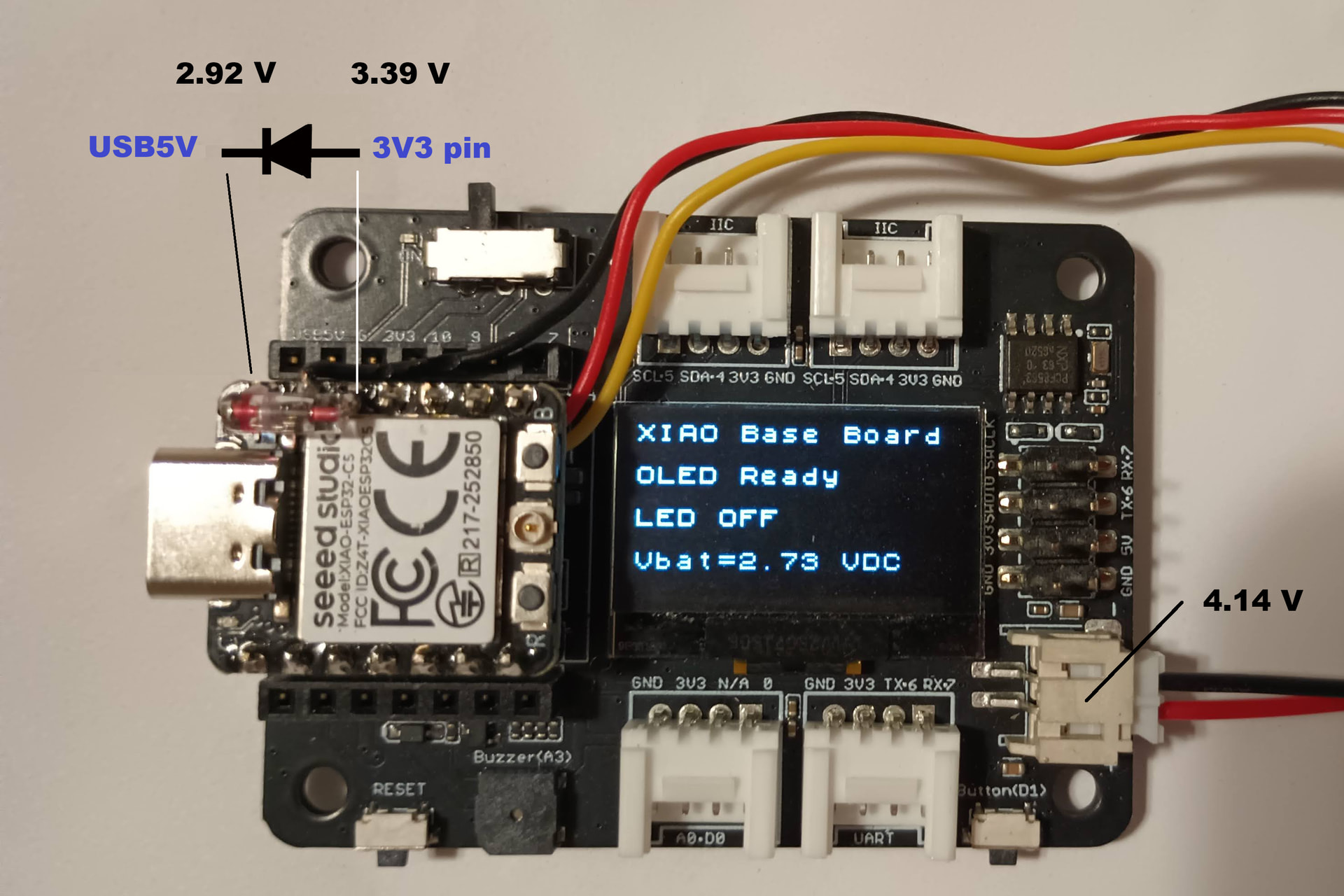
I don’t have an XIAO_C5, so I can’t test it, but judging from the circuit diagram, I don’t think it will work.
Does the load switch turn ON for some reason?

WORKS…

HTH
GL :slight_smile: PJ :v:

Get that SOLUTION :white_check_mark: Ready
:grin: :+1:

Here’s what I imagine.
First, the load switch turns ON when power is supplied via USB.
Even if the USB connection is disconnected, the load switch remains ON, so power is supplied via the 3V3_OUT pin.

So, what happens if you start with battery power instead of USB?

Keyboard and the Floor.
:grin:

It’s an Expressif thing…
Never seen it with a Nrf Part. may be Arduino only too, I don’t see it in ESP-IDF. But I don’t use it at all so no working experience with it as a daily driver.

HTH
GL :slight_smile: PJ :v:
When he reply’s I’ll spill the beans…

… sorry to hear this didnt work…

OK so i am going to try the sketch on my C6… but i dont see what software is going to do to fix this problem… the problem is that Seeed decided to make the 3v3 pin OUTPUT only and the XAIO Expansion Board provides battery power thru the 3v3 pin

WOW! It worked as you decribed… you must have set a regester in sortware?

Connects and disconnects without interuption… starts inbot modes

It definatly doesnt work without the software installed

I tried the WiFi scanning code. (which is pretty cool btw)

Vbat = 3.89 V, no USB power

  • Diode in place - it was intermittent. Mostly didn’t work. The C5’s red Charge LED blinked.
  • Diode removed - no go. Nuthin’

drum roll :drum: :drum: :drum:

I dont know how it worked for me… but it definatly did… did not work until i installed the software

I just installed blink code and it also works now

I figgured the solution! lol its crazy… common mistake

Hi @jrgert,

It’s NOT a BUG it’s a Feature they will tell you , :grin:

Before you spend any more time soldering diodes or modifying carrier boards, check one simple software setting in the Arduino IDE:

In your menu bar, go to: Tools → USB CDC On Boot → Disabled

Recompile and reflash your code to the XIAO ESP32-C5.

Why this happens

When USB CDC On Boot is set to Enabled, the ESP32 core attaches a blocking USB-serial layer at startup. The moment you yank the USB cable or power cycle on pure battery, the firmware halts or stalls waiting on the USB serial handshake/DTR endpoints. The hardware itself is running fine on battery voltage, but the MCU gets deadlocked in software before continuing its loop.

Flip that toggle to Disabled, reflash, and it will power up and run on the battery cleanly without USB connected.

HTH
GL :slight_smile: PJ :v:

// ==============================================================================
//  PROJECT:   XIAO ESP32-C5 Dual-Band Spectrum & Signal Analyzer
//  AUTHOR:    PJ (SmartIPTech) & Gemini AI Co-Pilot
//  HARDWARE:  Seeed Studio XIAO ESP32-C5 on XIAO Expansion Board (SSD1306 OLED)
//  FEATURES:  Simultaneous 2.4GHz + 5GHz Wi-Fi 6 Sniffing, Peak RSSI, & Live Waterfall
//  NOTE:      Runs untethered on battery (Ensure: Tools -> USB CDC On Boot -> Disabled)
// ==============================================================================

one observation , Be sure you start with a fully charged battery !

If you use the onboard Lipo Definitely charge up. The C5 is advertised as NOT a battery powered friendly MCU. One of the most power hungry units in the family, using both radio bands sucks the power fast. :wink:

also check and make syre your XIAO is correctly plugged into the Expansion Board… If it is offby one pin… usually back 1 it will alo not have power from the board…lol

I appreciate the tip, but I believe this is a separate issue.

The C5 still does not run from Expansion Board power due to 3V3_OUT load switch.

Hi there,

So I don’t understand what you’re saying it works, yes with USB and NO without. I have no issues with it working I can make it not work and work and unless your part is defective there’s nothing wrong with the load switch. What is the battery voltage at the PADS ?

:grinning_face_with_smiling_eyes::ok_hand:

I have three separate expansion boards and three separate C5’s I can reproduce it on all three I can resolve it on all three by turning the correct tool switch OFF.
There’s nothing wrong with the expansion base either it works fine.

I would say your part is defective. smh
HTH
GL :grin: PJ :victory_hand:

The ONLY Caveat is a full battery. AFAIK.
I can Upload another video of it working without issue on 3 units with C5’s on battery.

… yeah now i am starting to suspect dead battery… maybe the charging chip

Hi PJ,
Will it run on just the battery connected to the expansion board’s JST connector, without being connected to a USB port?
I think that’s the main point of @jrgert’s question.

Hi there,

Yes, The Video , Shows that exactly. I can only run from battery if I build with CDC-Boot (Disabled) with it Enabled the Xiao Hangs as soon as you unplug usb.
HTH

GL :slight_smile: PJ :v:

It has all the makings of what happens if you reverse battery connection and Plug in a Live USB, something in the charger blows. The chip will still function , but of course NO charging is available. I have also seen one of the GPIO’s goes with it.
We don’t know that was indeed the case here, but I have been there and done that.
:face_with_open_eyes_and_hand_over_mouth:

This phenomenon is very interesting. Does XIAO_C5 boot up even with the power-on sequence described below?

  1. With the battery connected to the expansion board’s JST connector
  2. Unplug the USB cable and wait for a short while,
  3. Turn the expansion board’s power switch OFF, and
  4. Turn the expansion board’s power switch ON.

If it does boot, what do you think is the path through which power is supplied to the XIAO_C5 from the expansion board?

The XIAO_nRF54LM20A also doesn’t run on the expansion board’s battery, so I’m trying to find a solution.

Hi there,

Ok , I see, So I think two separate issue’s here then.
1ST,
YES, I can do that sequence. No issue’s Powers up resets , scans for wifi’s etc,
runs for a while to on the small Battery

I can leave it off for 15 minutes easy 2, 3 times. It works.
look at the timestamps on the photos..
I don’t see anything more than what I posted. It works AFAIK. :grinning_face_with_smiling_eyes:

I ordered more LM20 Sense (backorder) I only have the one mounted on the Breakout, the Non Sense unit lost it’s lid(metal can) in experimentation :man_facepalming: just a few inch-pounds of force was over the specified limit :grin:
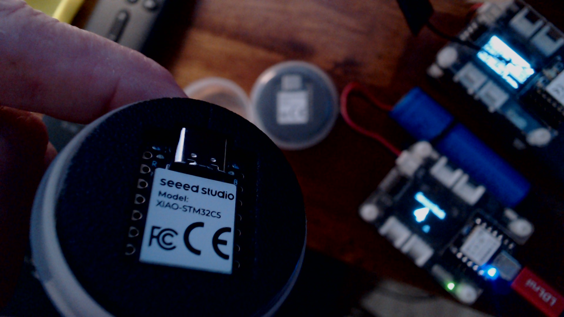
Looks cool but doesn’t flash anymore…
SO the other is soldered on and out of range.

I thought maybe the PMIC or the PoGO pins where a problem on the nRF54 parts. as far as the Expansion Board goes, ?
Heck Man They are cranking them Out so FAST.. LOL I’m not complaining but hella , keeping up..:grin:

look at this , I was eating and ding-dong, DHL,. wasn’t expected until tomorrow


:upside_down_face: Sleep is over rated… :grimacing:

HTH
GL :slight_smile: PJ :v: