I’m using Arduino to program a XIAO ESP32-C5, labeled 3/15/26.
I have a simple program up and running on Expansion Board v1.1 - when powered via USB C on the XIAO ESP32C5 module. I have a 3.7V LiPo battery connected correctly and it is charged to 4.15V.
The Arduino program does not use Serial.
When working, the program blinks the ESP32C5 user LED and writes to the I2C display on the expansion board. The ESP32C5 module has 3.39V on its 3V3 pin and 5.02V on USB5V pin.
The problem is: When I disconnect the USB-C from the ESP32C5, the program stops running. The ESP32C5 module has 3.39V on its 3V3 pin and 0V on USB5V pin. The I2C display keeps its last screen info.
I can power the ESP32C5 with a wall wort USB supply - and it works, it runs. It just doesn’t run of the battery alone.
I gotta be missing something, so if anyone can point me in a direction, I’m all ears.
So can you Use the code tgs above “</>” and paste your code in there,
We can look, I would bet the BSP or LIB version is the root cuase
Your display is a dead give away.
So , you are no crazy or the code is NOT bad, so.
If it was connected backards to the battery, then USB plugged in the Battery charger chip gives up the Ghost. You have any other Xiao’s on hand ?
I had this same scenario on a nRF52840 long ago, but exactly the same, CAN you tell if it charges the battery (meter) if the answer is NO, it’s not. then they are defective. “you may need to discharge the battery a little to get it to wake up”
hit support up for replacements.
HTH
GL PJ
P.s. The nRF52840 like that, I have and it STILL works , no battery operation or charge but everything still works.
apply the 5V and ground directly to the pins, make sure the on off switch is not broken… several of my expansion boards the switch has broken due to shock damage. apply battery directly to the underside of the board
The Expansion Board v1.1 JST battery connector battery leads are good; + is plus and - is GND.
The switch works on the Expansion Board and the Round Display and are not broken.
Attaching the battery to the ESP32C5 BAT pins “works”, but it bypasses the power switch on the Expansion Board and the Round Display, so not a good solution.
For my custom board, I have attached +5V through a diode to the 5V pin and the same issue exists - only starts and runs with USB-C power applied.
This is my interpretation based on the circuit diagram.
When the expansion board is not receiving power from the USB
port, it generates 3.3V from the JST battery and supplies it to the XIAO’s 3V3 pin. However, since the 3V3_OUT pin on the XIAO_C5 is dedicated to outputting 3.3V, it cannot supply 3.3V to the XIAO’s internal circuitry. Therefore, the XIAO_C5 will not operate using the expansion board’s JST battery. The same issue occurs with the XIAO_nRF54LM20A.
A load switch, TPS22916CNYFPR, is labeled ‘backflow prevention’ on the XIAO ESP32C5 schematic block diagram.
There must be an edge case, or power supply bounce, or…, where removing USB power allows the load switch to remain enabled long enough to allow +3V3_OUT to backfeed to +3V3.
So originally they only used it to power other sensors, USB and BAT were the main source of power. Wasn’t until someone got cute with the diode and back feeding the 3.3v directly ,then it was a 5v zener or something … started getting out of the rehlm.
So, I’m good with the way it used to work. makes more compatable to use it with a PMIC also. (you control the ON/OFF of the 3.3 volts for sensors & sleep)
YES as my head was hitting the pillow i remembered the Great Diode Fudes
So you have to put a diode from the 3v3 to the 5v pin to allow power from the 3v3 pin to support power on 3v3 pin as in the expansion board battery power system.
this is because you can apparently apply 3v3 power to the 5v pin and it will pass thru the voltage regulator and power the XIAO.. BUT if you accidentally connect to USB the 5 v will backfeed
It pisses me off because they say.. “there was no standard” but the whole XAIO ecosystem is founded on the Expansion Board and the Book that was written in Germany to make the XIAO SAMD
Also it is a clone of the Adafruit Feather
So they distroy the whole ecosystem because someone was working on a toy gadget project… and they provided "USER FEEDBACK’ SMH
 PJ


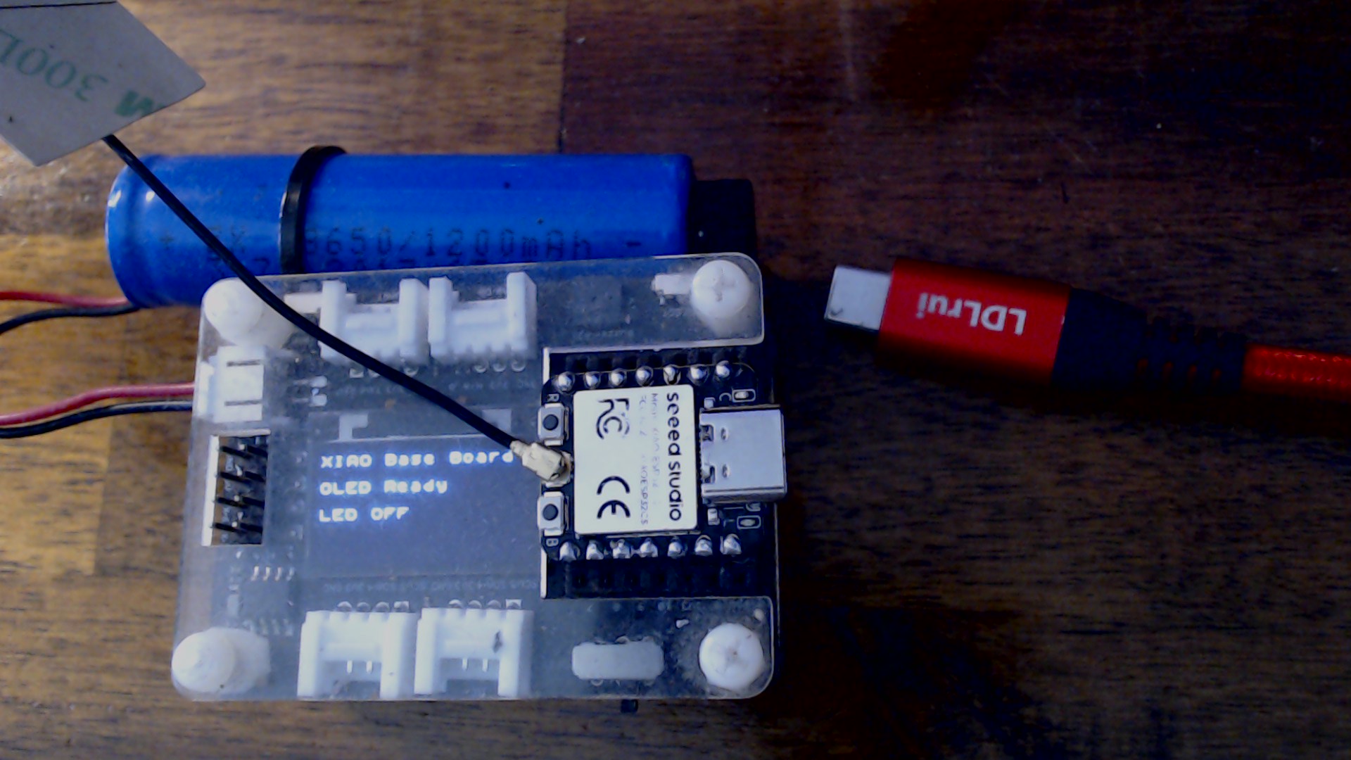
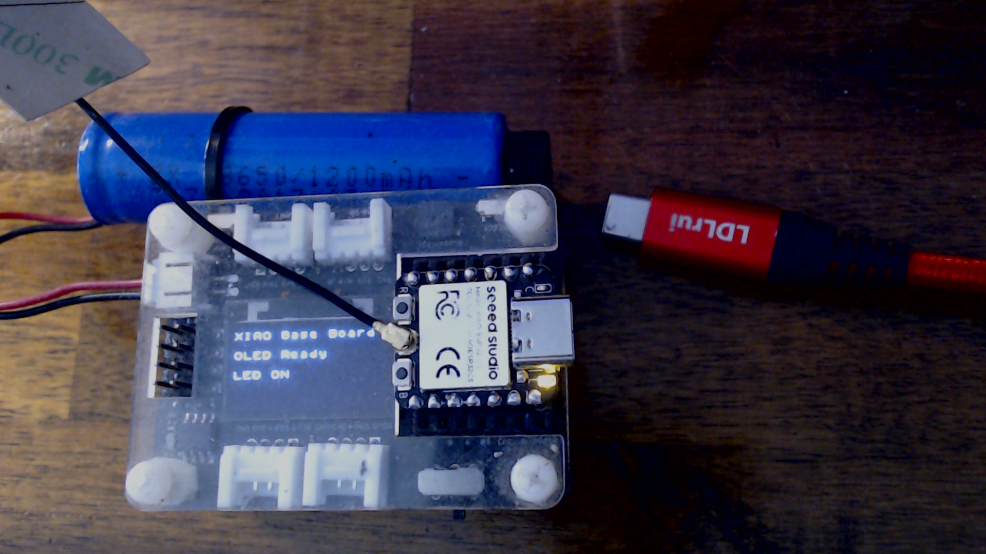


 Must be an edge condition somewhere.