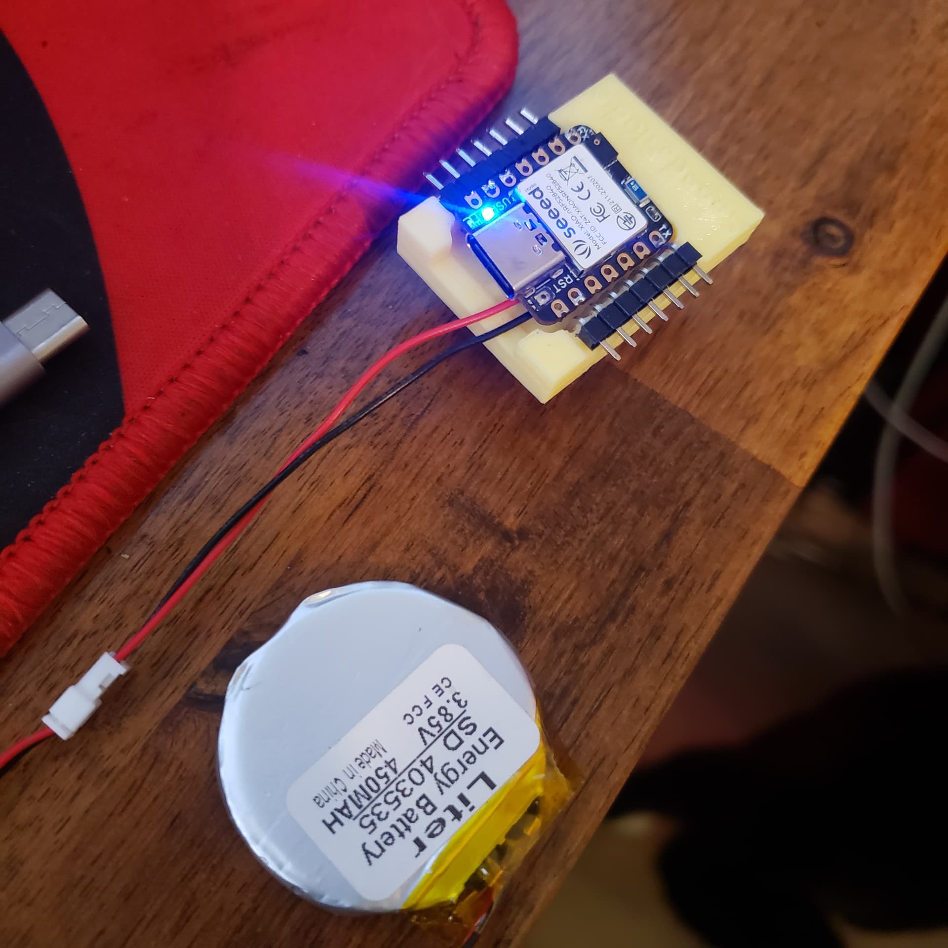
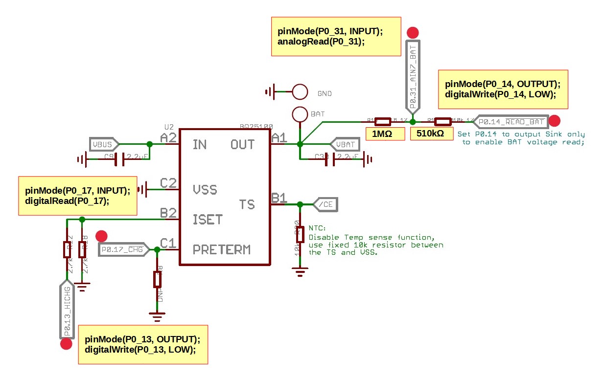
XIAO_BLE_Sense has battery charging and battery voltage monitoring functions. I am trying to check these functions with “mbed 2.7.2”.
The charging function worked as expected, but “analogRead(P0_31)” to read the battery voltage did not work. To check, I tried other analog pins from A0 to A5, and “analogRead()” worked without any problem.
After much analysis, it seems that there is a problem in the macro “analogPinToPinName(P)” used in the “analogRead()” function. In the definition, “g_APinDescription” (digital pin description) is used instead of “g_AAnalogPinDescription” (analog pin description).
/Arduino15/packages/Seeeduino/hardware/mbed/2.7.2/cores/arduino/wiring_analog.cpp : 89
int analogRead(PinName pin)
{
  for (pin_size_t i = 0; i < NUM_ANALOG_INPUTS; i++) {
    if (analogPinToPinName(i) == pin) {
      return analogRead(i + A0);
    }
  }
  return -1;
}
/Arduino15/packages/Seeeduino/hardware/mbed/2.7.2/cores/arduino/pinDefinitions.h : 22
#define analogPinToPinName(P) (P >= PINS_COUNT ? NC : P < A0 ? g_APinDescription[P+A0].name : g_APinDescription[P].name)
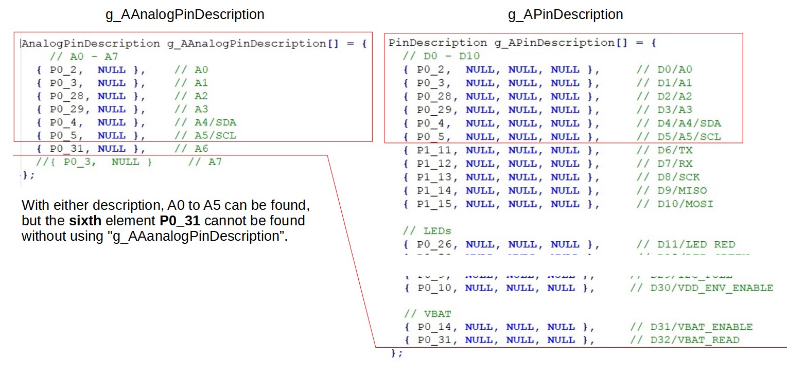
I changed “g_APinDescription” to “g_AAnalogPinDescription” and now “analogRead(P0_31)” also works as expected.
//#define analogPinToPinName(P)       (P >= PINS_COUNT ? NC : P < A0 ? g_APinDescription[P+A0].name : g_APinDescription[P].name)
#define analogPinToPinName(P)       (P >= PINS_COUNT ? NC : P < A0 ? g_AAnalogPinDescription[P+A0].name : g_AAnalogPinDescription[P].name)
my sample sketch
void setup()
{
Serial.begin(115200);
// while(!Serial);
pinMode(P0_31, INPUT); //Battery Voltage monitoring pin
pinMode(P0_13, OUTPUT); //Charge Current setting pin
pinMode(P0_14, OUTPUT); //Enable Battery Voltage monitoring pin
digitalWrite(P0_13, LOW); //Charge Current 100mA
digitalWrite(P0_14, LOW); //Enable
analogReference(AR_INTERNAL2V4); //Vref=2.4V
analogReadResolution(12); //12bits
}
void loop()
{
digitalWrite(LED_GREEN, LOW);
delay(500);
int Vadc = analogRead(P0_31);
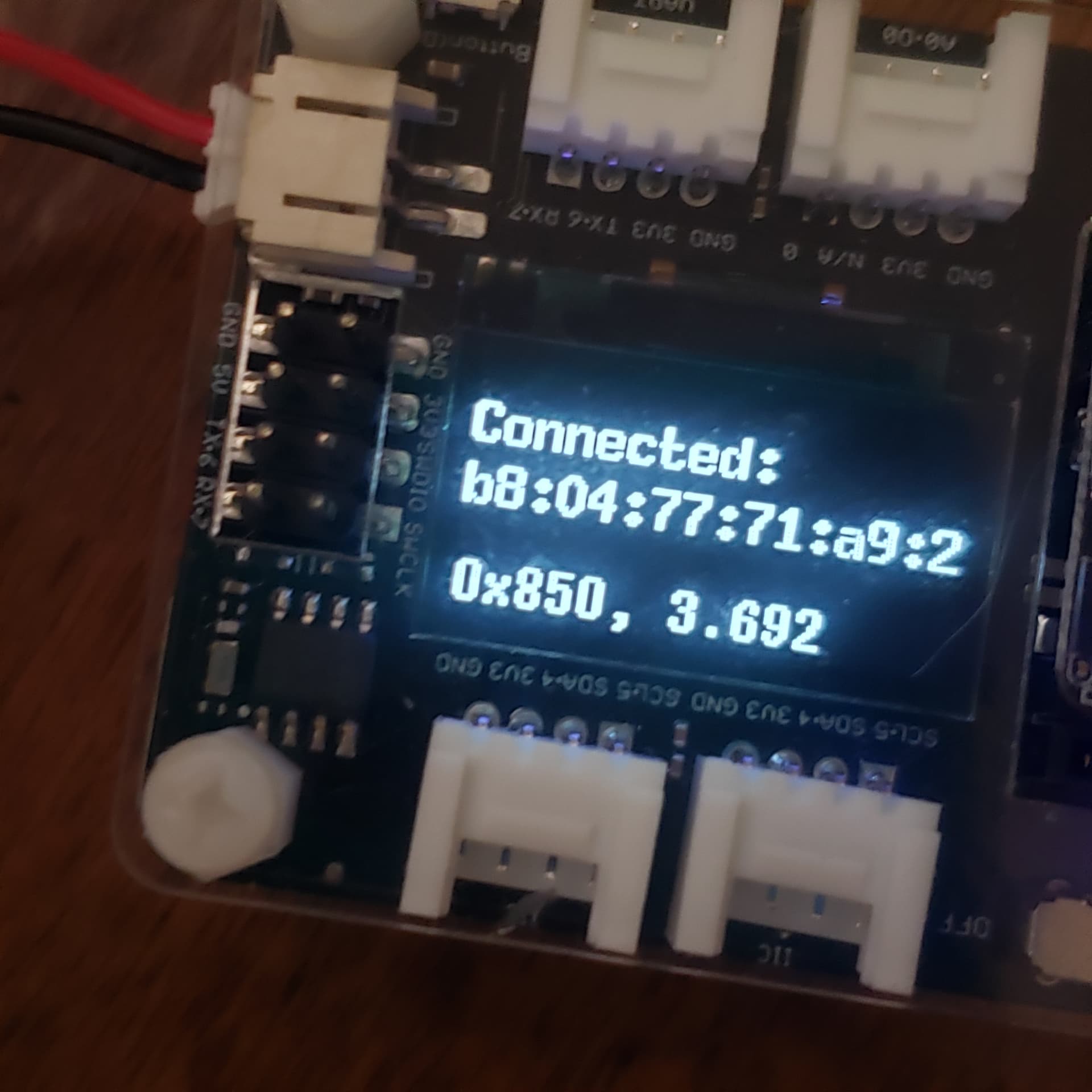
float Vbatt = ((510e3 + 1000e3) / 510e3) * 2.4 * Vadc / 4096;
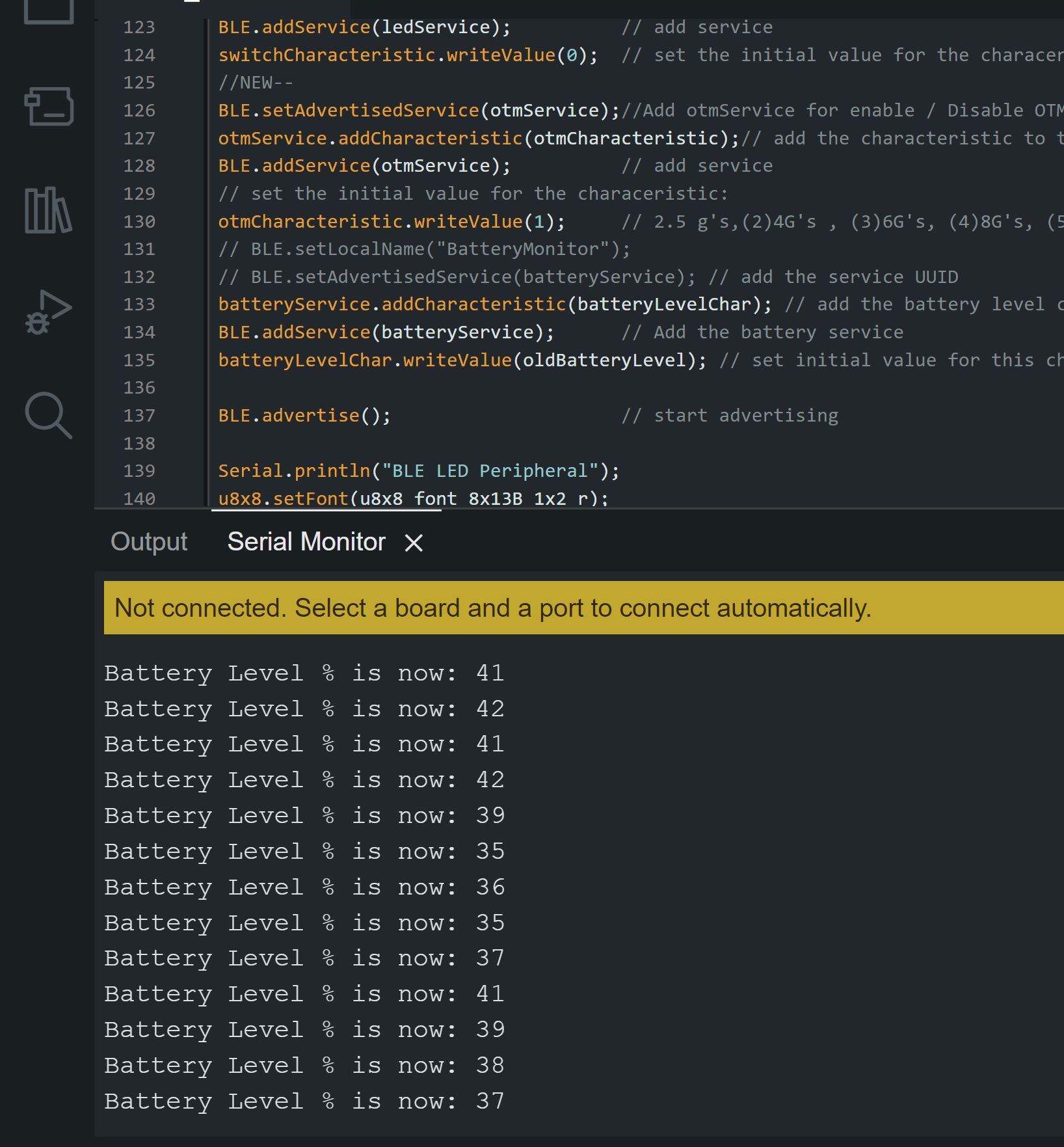
Serial.print("0x");Serial.print(Vadc, HEX);
Serial.print(", ");
Serial.println(Vbatt, 3);
digitalWrite(LED_GREEN, HIGH);
delay(500);
}