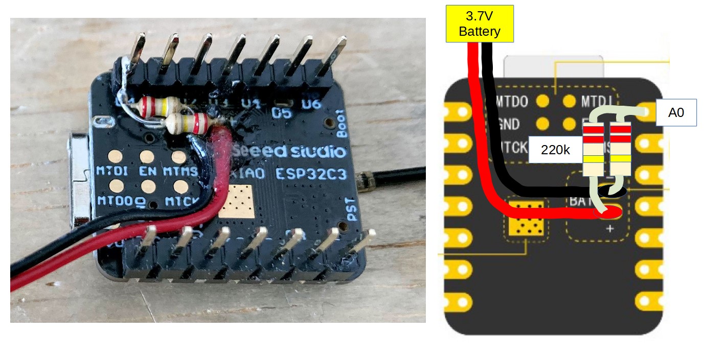
The battery pad of XIAO_ESP32C3 is not connected to any port, so the battery voltage cannot be read and there is a risk of over-discharging the battery.
(XIAO_BLE has a port connected to the pad and can read the voltage.)
The battery voltage was divided by 1/2 with 200k and connected to the A0 port so that the voltage could be monitored.
About the AD conversion of the ESP32C3
The datasheet says nominally 2500mV full scale AD conversion, but there is a large variation from chip to chip, actually ±10%. My chip was 2700mV full scale.
Fortunately, the calibrated correction value for each chip is written in the fuse area, and by using the function alalogReadMilliVolts(), I can read the corrected voltage value without doing anything special.
The result of AD conversion and the voltage measured by the multimeter agree well with each other with an error of about 5 mV, which is not a problem in practical use.
In addition, during communication in particular, spike-like errors occurred, which had to be averaged out 16 times to remove them.
I wonder if there’s any way to use the matrix mapping in the ESP to actually attach a port/pin to the battery? It’s not so hard to add a voltage divider, but it seems almost impossible to understand why this board has a charger but can’t read the battery charge!
Hence the Voltage divider youtube video :-), either intentional?(without explanation) or a HUGE, GIGANTIC fail by whomever at Seeed Engineering.
SMH ;-p
Just what I was looking for, this sounds great, any idea how much power it would draw, hence reducing battery life? Any way to prevent/decrease loss. I’ve seen similar diagrams 45k and 100k resistors (different multipliers) which would be more efficient, decreasing power draw. Any chance the -C6 version corrects this and uses a pin to monitor directly?
Good morning,
Having only 1M resistance on hand, I would like to test what you suggest. Should I change the sample code?
Sorry I’m not very strong in electronics, I’m more of a developer.
THANKS
Thank you, I have the impression that the measurement is not precise on the other hand, I do not have the same value at all as that measured with a multimeter.
One source of inaccuracy is the tolerance of the resistors. A typical tolerance would be 5%. Say in the worst case one resistor is off from its nominal value by +5%, and the other is off by -5%.
Then the voltage result you get will be off by 5% as well:
Thank you for all those informations.
However, I don’t know how but I feel like I burned my board. it must surely be the 3V3 regulator, the card is no longer recognized when it is plugged in via usb and the 3V3 pin is at 0V.
Thanks for the technique. I am using this and it works wonderfully. I have a concern though:
My max measurement is around 4.2V on full charge, which is as expected. However, my lowest measurement could go all the way down to 2.8V (or may be further), which I believe may damage lithium batteries.
Doesn’t the xiao esp32c ldo have a cut off value that is safe for lithium batteries? If not, how could I enforce this in HW?
I have examined the schematic and it does not seem to include a function to read the battery voltage. The battery terminal voltage must be resistively divided and connected to the XIAO port for AD conversion.
(The battery pad on the back of the XIAO is not connected to this Grove-Shield.)
Have you found anything interesting about this? i am planning on connecting a bare 18650 battery without protection and if what you mention is correct it is not safe…
Hi, I hope someone could help me with the problem I encountered. I am using XIAO SP32C3 together with BMP280 sensor in my product. The code and hardware are pretty simple, basically driving two LEDs depending on the pressure. It all worked well, until today I added this code for checking the battery voltage. The battery code works well, but the BMP280 stopped sending the parameters to the serial monitor, and I’m just getting NAN instead. I just added the voltage divider, two 220K resistors as suggested and I also added 3 colored LEDs to the free pins A1, A2 and A3, which wee previously unused, so in fact I haven’t changed anything, just added the above. If I upload previous code without the battery check part, BMP works without problems. So I wanted to ask if there may be some known issue with using both ADC and I2C, or something like that?
I would really like to be able to use the battery check part. I have 150 boards and this XIAO board really has some weird solutions, like almost no indication, charging current of 350mA which is pretty scary considering I’m using LiPo poach battery 150mAh and I’d really prefer if they don’t start exploding once delivered to users, etc. I’ve been using nRF52840, but decided to switch to ESP, frankly mostly because of the price, because any board would do, providing it has a charging capability, and that’s where I haven’t been careful enough. The battery does have some kind of protection circuit, consisting of 8205A and something called G3JS, but I don’t know if that’s sufficient enough, so if anybody knows more, I’d appreciate any help, with this and the problem above.
Hi Mishko959,
I wrote a proper sketch and tried it, it worked fine on 3.7V battery power.
If you give me your sketch, I can try to run the same configuration with battery voltage check, BMP280 and LEDs at the same time. You can direct mail me instead of posting it.
The charge current of the nRF52840 is 50mA or 100mA in the configuration, while the charge current of the ESP32C3 is 370mA. The link below has the results of my measurements. However, if there is some kind of overcurrent protection on the battery side, it should be protected. The 8205A you mention seems to have overcharge detection, but G3JS doesn’t have a datasheet so I don’t know if it can be used. I would recommend that you actually measure the charging current.
‘Charging characteristics of XIAO_nRF52840 and XIAO_ESP32C3’