Battery voltage monitor and AD conversion for XIAO_ESP32C

Hi msfujino,

Thank you for the prompt reply. And I’ll only be happy to send you the code, of course. Where can I find your email address, in your profile? I’m a total newbie here, and haven’t even looked around properly so far.

Your code seemed spot on to me, though, and unless it was just some kind of coincidence, it was showing the correct voltage to the second decimal place. I took a brand new battery from the package, and checked the voltage before I attached it to the circuit, and it was around 3.8V, which is the same result I’ve got from your code. I used the standard resistors, because I don’t have any with tighter tolerance, although I did measure a number of them to select two with as equal resistance as possible. In fact, the only problem was that everything else stopped working, your code was working flawlessly. Now that I changed V0 to V2, though, it’s sending totally random values, although the actual voltage is the same as before.

I’ve read all the stuff from your links when I first visited this forum, and saved and checked your image about charging characteristics. I thing I have datasheets of both components, although I need to find the one for G3JS. If I find it, I can email you both.

Last time I visited this site, I stumbled upon some kind of XIAO dedicated page and there the charging current of ESPC3 was 350mA, not 370. I guess the designer of this board sobered a bit, and tried to tone down that epic choice of parameter a little :slight_smile:

I had other problems with this board today. The upload ended with fatal error a couple of times, with the message about lost connection, and I was using two boards, so it was not a malfunction of just one of them. I’ve read somewhere on this forum if I recall correctly, that I should always reboot by using both buttons in sequence before the upload, but I mostly did not do that and everything worked anyway, and then failed exactly after I did. So all in all, this board seems kind of inconsistent, at least in comparison with other XIAO boards, as much as I can say, although I’m far from being any kind of authority when it comes to programming…

OK, thanks again, I’ll try to find your email address here, and send you the code and datasheets, and if it can’t be found, you can PM me, or however it’s done around here.

Cheers,

Miso
When running on battery power without a PC, if there is a while(!Serial) in the sketch, it waits for the serial monitor and does not work forever.

Did you change the wiring to A0 to A2, and did you change the ADC input pin from A0 to A2 in the sketch?

The charge controller is an ETA4054, and the calculated value is 360mA with the set resistance R22=2.7k in the schematic, and the measured value is 370mA.

The solution to the problem of not being able to upload is on the ESP32C3 wiki.

For direct mail, click on my icon and then click on the message symbol and you will be able to write an email. But for anyone else having the same problem, I think it would be better to post it here.

edit:
I charged a 220mAh battery with built-in protection circuit as a test. The battery is charged at 370mA from XIAO. It seems that the protection circuit does not have a function to suppress the charging current to a safe value, and it is necessary to limit it on the charging circuit side.

1 Like

Hi msfujino.

I have stumbled on your post and wanted to replicate what you were doing on a XIAO ESP32-S3, using the A9 analog pin. I tried it with a battery pack I assembled using 2 Li-Ion batteries in parallel with ~10800mAh capacity, so the voltage was (at the time of testing, measured with 2 different measuring instruments) 4.11V. The measured voltage from A9 pin was 4.02V (average over 100 measures, with 100ms between every measurement). I used your code, only modified to measure 100 different values, instead of 15, to get a more realistic average and I added a function that sends the result from the measurement to Slack, as I already had code ready for that and the ESP wasn’t connected to a serial port.

My question is, why is there a 90mV error during measurement and what can I do to avoid it. I tried measuring different voltages from a programmable power supply, and the measurement error is not linear, so adding an offset is not plausible.

Thank you in advance!

i think the ADC is comparing to VCC, so if VCC fluctuates, then the reading also… it is not designed to truly be a multimeter

yall probably got past this already, but i am thinking that something in the circuit is causing a short circuit that is causing a high current draw and browning out the chip… atleast the chip browns out before it burns out…

Hi cgwaltney,
Have you read the following document?
The Vref of the ESP32S3’s ADC is 1.1V, which is internally generated, not VCC; it is not affected by VCC.
And you can use analogReadMillVolts() to get millivolt values with factory calibrated Vref.

Analog to Digital Converter (ADC) - ESP32-S3 - — ESP-IDF Programming Guide v4.4 documentation

ADC - - — Arduino ESP32 latest documentation

1 Like

Hi Bklaric,

  1. the first possibility is variation in the voltage divider resistors. The resistors should be selected and as close to the same value as possible, or the result of analogReadMillVolts() should be corrected for the variation, instead of multiplying by 2.
  2. The next consideration is the accuracy of your measurement device; you need to decide which of the ADC accuracy or the accuracy of the measurement device to use.
  3. connecting 100nF between the ADC input pins and GND may help.
1 Like

https://docs.espressif.com/projects/arduino-esp32/en/latest/api/adc.html

It is alot of complicated stuff going on in the background that may result in an error between what you read and what it says… like i said before, the chip is not a multimeter, at the end of the day it is taking a binary number and converting it into a decimal number that it presents to you as a millivolt

It is alot of complicated stuff

Have you read the function analogReadMillVolts() to see what complexities are involved?

at the end of the day it is taking a binary number and converting it into a decimal number that it presents to you as a millivolt

Have you estimated how much error is involved in converting binary to decimal and then to millivolts? If you know, please let me know.

I do not know

analogReadResolution

This function is used to set the resolution of analogRead return value. Default is 12 bits (range from 0 to 4095) for all chips except ESP32S3 where default is 13 bits (range from 0 to 8191). When different resolution is set, the values read will be shifted to match the given resolution.

Range is 1 - 16 .The default value will be used, if this function is not used.

Note

For the ESP32, the resolution is between 9 to12 and it will change the ADC hardware resolution. Else value will be shifted.

ADC OneShot mode

The ADC OneShot mode API is fully compatible with Arduino’s analogRead function. When you call the analogRead or analogReadMillivolts function, it returns the result of a single conversion on the requested pin.

analogSetAttenuation

This function is used to set the attenuation for all channels.

Input voltages can be attenuated before being input to the ADCs. There are 4 available attenuation options, the higher the attenuation is, the higher the measurable input voltage could be.

The measurable input voltage differs for each chip, see table below for detailed information.

ESP32ESP32-S2ESP32-C3ESP32-S3

Attenuation Measurable input voltage range
ADC_ATTEN_DB_0 100 mV ~ 950 mV
ADC_ATTEN_DB_2_5 100 mV ~ 1250 mV
ADC_ATTEN_DB_6 150 mV ~ 1750 mV
ADC_ATTEN_DB_11 150 mV ~ 3100 mV

Blockquote

So back to the original question… 90mV is within the stated tollerance of the chip

1 Like

yes, take a look at the link i provided

https://docs.espressif.com/projects/arduino-esp32/en/latest/api/adc.html

Thanks for the reply. I will not discuss this any further as the discussion seems to be losing specificity.
I will wait for Bklaric’s reply.

2 Likes

Thanks for the response msfujino and sorry for the late reply.

  1. The values of the resistors is not completely perfect, they are 215.4 kOhm and 218.1 kOhm. To account for the different values, I adjusted the multiplication with 2. Instead of 2, I used 2.01253481894, which corresponds to (215.4 + 218.1)/215.4. That seemed to make the error a bit better.
  2. I measured the battery voltage with 3 different measuring devices, which I tested before with constant voltage, and they are accurate.
  3. I haven’t tried putting a 100nF decoupling capacitor, but can try it later today.

I tried to ramp up the voltage and measure the difference. I used a lab power supply and got these values:

  • Input Voltage: 3.50 V < → Measured Voltage: 3.41263 V
  • Input Voltage: 3.60 V <-> Measured Voltage: 3.51939 V
  • Input Voltage: 3.70 V <-> Measured Voltage: 3.60384 V
  • Input Voltage: 3.80 V < → Measured Voltage: 3.70474 V
  • Input Voltage: 3.90 V <-> Measured Voltage: 3.80346 V
  • Input Voltage: 4.00 V <-> Measured Voltage: 3.90416 V
  • Input Voltage: 4.10 V <-> Measured Voltage: 4.00318 V
  • Input Voltage: 4.20 V <-> Measured Voltage: 4.10144 V

The input voltage corresponds to power supply voltage. The measured voltage uses your code for one value, then repeats that 100 times and extracts the average from that. The error fluctuates between 0.081 and 0.099, with the average of 0.093 and the delta difference between min and max error from 0.018.

If you have any more suggestions, how I could solve this, would be pretty nice, as adding an offset is not exactly the solution. But thank you in any case!

Bklaric,
Since the internal circuit is not disclosed, this is a general theory and my imagination.

The reason why the AD conversion value is smaller than the input voltage may be due to the effect of the voltage divider circuit.
There is a sample-and-hold circuit at the input of the AD conversion circuit, which samples and holds the input voltage in a small capacitor and converts the voltage of the held capacitor to AD. If there is no voltage divider circuit, the input voltage is sampled and held with a small time constant, and the input voltage and the capacitor voltage almost match.
However, if the resistance of the voltage divider circuit is as large as 220k, the capacitor voltage rises slowly with a fairly large time constant and is held before it fully reaches the input voltage. As a result, a value lower than the input voltage is AD converted.
To check this, try 2k2 instead of 220k, and the difference will be smaller. Also, if you connect 100nF to the input pin, the difference will be smaller because the capacitor will sample and hold without passing through 220k.

In any case, if you are using an accurate measuring instrument, I would recommend adopting its value to correct the AD conversion result.

1 Like

Hi.
Can i connect resistor to A1?

msfujino,
I tried it yesterday with the 100nF capacitor and tried lowering the resistors and voilà the measured voltage was almost exactly the same as the input voltage. With just the capacitor, there is still like 15-20 mV error, but much more manageable and tiny bit more linear.
Thank you for your help!

1 Like

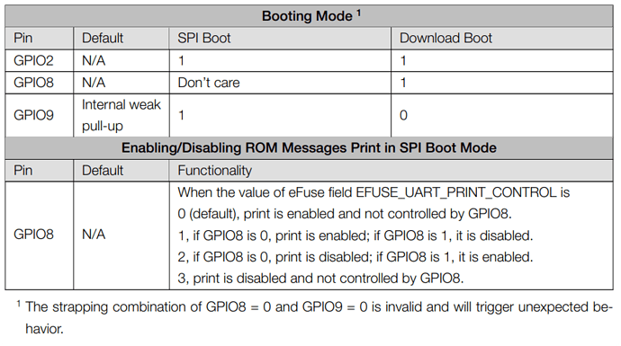
If it is the ESP32C3 you are using, then A0 (GPIO2) and A1 (GPIO3) are strapping pins that have different functions at power-on and should not be used to avoid trouble.

A1 (GPIO3) is not strapping pin, nothing about it in datasheet!
Just GPIO2, GPIO8 and GPIO9 are strapping pins.

See “ESP32-C3 Technical Reference Manual, Table 7-2, Boot Mode Control”
To avoid unnecessary trouble, I thought it would be better not to use it.

msfujino,
thanks for your help.