XIAO BLE Sense - LSM6DS3 INT1 Single Tap Interrupt

Hi, I’m trying to get the “Single Tap Interrupt” from the integrated LSM6DS3 working on XIAO BLE Sense.

As far as I know from the schematics, Int1 of LSM6DS3 is connected to P0.11 from NRF52480, which is the digital pin 18, as defined by PIN_LSM6DS3TR_C_INT1 .

In my following code, I try to set up the “Single Tap” recognition on LMS6DS3 as described via Application Note. I also used as reference the interrupt set up from another board, which is published by sparkfun.
Unfortunately, no interrupt is generated.

I was able to verify, that at least my pin assumptions must be correct, by optionally setting the “Interrupt Level Activation” from default HIGH, to optinally LOW via LSM6DS3_ACC_GYRO_CTRL3_C register. For these cases, I was able to read the non active interrupt pin regarding as HIGH or LOW.

Did anybody already set up a working interrupt from LMS6DS3 on this board? Any corrections regarding my code?

Thanks in advance!

#include "LSM6DS3.h" // from Seeed_Arduino_LSM6DS3 Package
#include "Wire.h"
#include "SPI.h"

//Interrupt variables
#define int1Pin PIN_LSM6DS3TR_C_INT1 //Pin 18
uint8_t int1Status = 0;

LSM6DS3Core myIMU( I2C_MODE, 0x6A );

void setup()
{
	Serial.begin(9600);
	delay(1000); //relax...

	//Call .beginCore() to configure the IMU
	if( myIMU.beginCore() != 0 )
	{
		Serial.print("Error at beginCore().\n");
	}
	else
	{
		Serial.print("\nbeginCore() passed.\n");
	}

	//Error accumulation variable
	uint8_t errorAccumulator = 0;

	uint8_t dataToWrite = 0;  //Temporary variable

  // Turn on the accelerometer
  // ODR_XL = 416 Hz, FS_XL = 2g
	errorAccumulator += myIMU.writeRegister(LSM6DS3_ACC_GYRO_CTRL1_XL, 0x60);

	// Enable tap detection on X, Y, Z axis, but do not latch output
	errorAccumulator += myIMU.writeRegister( LSM6DS3_ACC_GYRO_TAP_CFG1, 0x0E );
	
	// Set tap threshold
	errorAccumulator += myIMU.writeRegister( LSM6DS3_ACC_GYRO_TAP_THS_6D, 0x09 );

	// Set Duration, Quiet and Shock time windows
	errorAccumulator += myIMU.writeRegister( LSM6DS3_ACC_GYRO_INT_DUR2, 0x06);
	
	// Only single tap enabled (SINGLE_DOUBLE_TAP = 0)
	errorAccumulator += myIMU.writeRegister( LSM6DS3_ACC_GYRO_WAKE_UP_THS, 0x00 );
	
  // Single tap interrupt driven to INT1 pin
	errorAccumulator += myIMU.writeRegister( LSM6DS3_ACC_GYRO_MD1_CFG, 0x40 );

	if( errorAccumulator )
	{
		Serial.println("Problem configuring the device.");
	}
	else
	{
		Serial.println("Device O.K.");
	}	

	pinMode(int1Pin, INPUT);
	attachInterrupt(digitalPinToInterrupt(int1Pin), int1ISR, RISING);	
}


void loop()
{
	if( int1Status > 0 )  //If ISR has been serviced at least once
	{
		Serial.print("Single-tap event\n");
		
		//Clear the ISR counter
		int1Status = 0;
	}

  Serial.print("Loop is alive...\n");
  delay(1000);
	
}


void int1ISR()
{
	//Serial.println("Interrupt serviced.");
	int1Status++;
}
1 Like

Hmm, would be interesting to see if this works with the new firmware that was said to becoming. As I’m hopefully going to have something similar to this. Unfortunately I cant really provide any tips at this moment as dealing with all these firmware issues is messing up everything

My understanding is that you want to use the XIAO BLE interrupts, have you tried using the external interrupt function attachInterrupt () directly? I’ll test it sometime using the simpler key interrupt test to determine if it’s an XIAO problem.

Thanks @Citric , I validated attachInterrupt() directly via accessable GPIO Pins.

I made progress on the topic and will post my solution after I am satisfied.
My Problem was, that I made the stupid assumption, that LSM6DS3TR-C (used for XIAO BLE Sense) is from a software developer point of view (register configuration etc.) the same as LSM6DS3, which is used in so many other Github projects.

But you all guess, it is not exactly the same. Most importantly, the TAP_CFG Register contains now an “INTERRUPTS_ENABLE” flag, which is needed for such functionalities and was not present before.

By the way, it is quite misleading, that in the official wiki for XIAO BLE Sense, the 6-Axis IMU Example uses “Seeed_Arduino_LSM6DS3” package, which does only apply LSM6DS3 Registers. Please consider to differentiate/support LSM6DS3TR-C too, in this package or another.

1 Like

Understood, I will discuss this matter with R&D later.

Here is my example, if anybody is interested.

At startup LED is blue, a double tap leads to an interrupt and LED blinks green. After 5 interrupts, XIAO BLE Sense goes into System OFF state (LED off), while LSM6DS3TR-C stays awake, looking for double taps. If another double tap occures, XIAO BLE Sense wakes up (LED blue).
If you want to monitor serial, be sure to close and reopen after wake up.

My current measurements (via battery tabs only):

  • XIAO BLE Sense and IMU active (gyro disabled - not needed for example): 1.68 mA
  • IMU active, XIAO BLE Sense in System OFF: 450µA

Because deep sleep is currently widely discussed: I did not modify the shipped bootloader, and i’m working with Board Firmware 2.6.1

/*****************************************************************************/
// IMU Interrupt Example for XIAO BLE Sense
// This example shows how to configure LMSD6S3TR-C on XIAO BLE SENSE to interrupt
// on INT1 after a "Double Tap" was recognized.
// Additionally, the device goes into System OFF state, after 5 interrupts were
// received. Another "Double Tap" will wake up the device again.
// 
// by chuck
/*******************************************************************************/

#include "LSM6DS3.h"
#include "Wire.h"

LSM6DS3 myIMU(I2C_MODE, 0x6A);
#define int1Pin PIN_LSM6DS3TR_C_INT1

uint8_t interruptCount = 0; // Amount of received interrupts
uint8_t prevInterruptCount = 0; // Interrupt Counter from last loop

void setup() {
    Serial.begin(9600);

    pinMode(LEDR, OUTPUT);
    pinMode(LEDG, OUTPUT);
    pinMode(LEDB, OUTPUT);
    setLedRGB(false, false, true); // set blue led

    myIMU.settings.gyroEnabled = 0; // Gyro currently not used, disabled to save power 
    if (myIMU.begin() != 0) {
        Serial.println("IMU error");
    } else {
        Serial.println("IMU OK!");
    }
    
    setupDoubleTapInterrupt();
    
    pinMode(int1Pin, INPUT);
    attachInterrupt(digitalPinToInterrupt(int1Pin), int1ISR, RISING);
}

void loop() {
    setLedRGB(false, false, true); // reset led to blue only

    Serial.print("\Iterrupt Counter: ");
    Serial.println(interruptCount);

    // if interrupt was received in this cycle
    if (interruptCount > prevInterruptCount) {
      Serial.println("\Interrupt received!");
      setLedRGB(false, true, false); // set green only
    }
    
    prevInterruptCount = interruptCount;
    
    if (interruptCount >= 5) {
      // Trigger System OFF after 5 interrupts
      goToPowerOff();
    }
    
    delay(500);
}


// -------------------- System ------------------------- //

void goToPowerOff() {
  setLedRGB(false, false, false);
  Serial.println("Going to System OFF");
  setupDoubleTapInterrupt(); // not needed here, if already applied..
  delay(100); // delay seems important to apply settings, before going to System OFF
  //Ensure interrupt pin from IMU is set to wake up device
  nrf_gpio_cfg_sense_input(digitalPinToInterrupt(int1Pin), NRF_GPIO_PIN_PULLDOWN, NRF_GPIO_PIN_SENSE_HIGH);
  // Trigger System OFF
  NRF_POWER->SYSTEMOFF = 1;
}

// -------------------- Interrupts ------------------------- //

void setupDoubleTapInterrupt() {
  uint8_t error = 0;
  uint8_t dataToWrite = 0;

  // Double Tap Config
  myIMU.writeRegister(LSM6DS3_ACC_GYRO_CTRL1_XL, 0x60);
  myIMU.writeRegister(LSM6DS3_ACC_GYRO_TAP_CFG1, 0x8E);// INTERRUPTS_ENABLE, SLOPE_FDS
  myIMU.writeRegister(LSM6DS3_ACC_GYRO_TAP_THS_6D, 0x8C);
  myIMU.writeRegister(LSM6DS3_ACC_GYRO_INT_DUR2, 0x7F);
  myIMU.writeRegister(LSM6DS3_ACC_GYRO_WAKE_UP_THS, 0x80);
  myIMU.writeRegister(LSM6DS3_ACC_GYRO_MD1_CFG, 0x08);
}

void int1ISR()
{
  interruptCount++;
}

// -------------------- Utilities ------------------------- //

void setLedRGB(bool red, bool green, bool blue) {
  if (!blue) { digitalWrite(LEDB, HIGH); } else { digitalWrite(LEDB, LOW); }
  if (!green) { digitalWrite(LEDG, HIGH); } else { digitalWrite(LEDG, LOW); }
  if (!red) { digitalWrite(LEDR, HIGH); } else { digitalWrite(LEDR, LOW); }
}
1 Like

This was helpful as I was just starting to implement a single tap that I wanted to exploit the interrupt that was wired on the XIAO BLE nRF52840 Sense.

Nice write ups and good work!

1 Like

Thank you so much for sharing this @chuck. Extremely helpful and thank you for posting the power consumption for this as that is my main priority.

1 Like

Hey, tried to test this out today but I cant seem to get the Seeed to stay in sleepmode. It just leaves sleep mode instantly for some reason. May I ask if youre powering this through usb or battery tabs.

Thank you

Hi @jonyu,
this example works for me in all cases, usb and/or battery. You could try to increase the delay provided in goToPowerOff function, if you haven’t already. This would rule out, that some rest vibration is waking your board while you’re going to sleep.

Just add
delay(100);
after
nrf_gpio_cfg_sense_input(digitalPinToInterrupt(int1Pin), NRF_GPIO_PIN_PULLDOWN, NRF_GPIO_PIN_SENSE_HIGH);
then the code will work for battery.

1 Like

This method worked for me thank you :slight_smile:

Hey @chuck when you were in sleep mode. Was there a way for you to save data during sleep mode. E.g storing imu data.

Hi @jonyu,
currently i didn’t need to save IMU data while sleeping. But you should be able to save your measurements (up 4kB i think) in integrated FIFO of LSM6DS3, and read everything at once after wake up.

@chuck thank you for the example code!!

did you manage to get any further optimisations in terms of power draw? would turning the mic off help? A couple of things I’m trying to get my head round:

  • what is the difference between sd_power_system_off(); and NRF_POWER->SYSTEMOFF = 1;
  • would sd_power_mode_set(NRF_POWER_MODE_LOWPWR);, sd_power_dcdc_mode_set(NRF_POWER_DCDC_ENABLE);, __WFE();, __WFI();, sd_app_evt_wait(); help at all?

I’m trying to get a battery powered wearable working which is effectively completely powered down (no mic, BLE, data persistence etc so system resets are fine) when not in use, but can be woken up/powered down with a double tap.

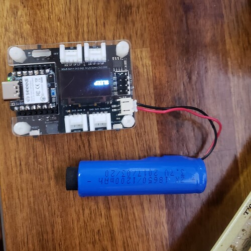
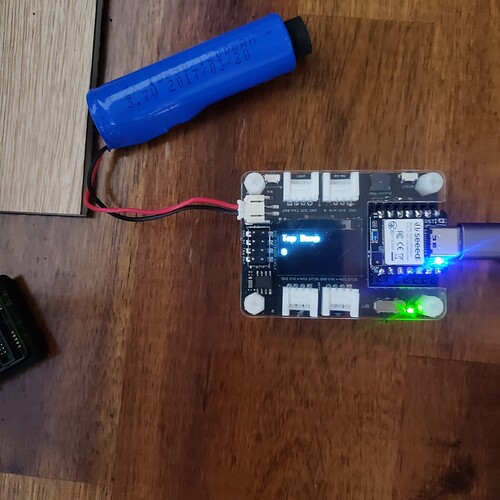
XIAO BLE Sense - LSM6DS3 INT1 Double Tap Interrupt Xiao Expansion Board OLED TAP DEMO
/*****************************************************************************/

// IMU Interrupt Example for XIAO BLE Sense

// This example shows how to configure LMSD6S3TR-C on XIAO BLE SENSE to interrupt

// on INT1 after a “Double Tap” was recognized.

// Additionally, the device goes into System OFF state, after 5 interrupts were

// received. Another “Double Tap” will wake up the device again.

//

// Original by chuck

Go See it running HERE------>>>Expansion Board TAP DEMO video


HTG
GL :slight_smile:

/*****************************************************************************/
// IMU Interrupt Example for XIAO BLE Sense
// This example shows how to configure LMSD6S3TR-C on XIAO BLE SENSE to interrupt
// on INT1 after a "Double Tap" was recognized.
// Additionally, the device goes into System OFF state, after 5 interrupts were
// received. Another "Double Tap" will wake up the device again.
// 
// Original by chuck
//poatched and toasted by pjg
/*******************************************************************************/

#include "LSM6DS3.h"
#include "Wire.h"
#include <U8x8lib.h>
LSM6DS3 myIMU(I2C_MODE, 0x6A); // IMU 
#define int1Pin PIN_LSM6DS3TR_C_INT1

U8X8_SSD1306_128X64_NONAME_HW_I2C u8x8(/* clock=*/ PIN_WIRE_SCL, /* data=*/ PIN_WIRE_SDA, /* reset=*/ U8X8_PIN_NONE);
 // OLEDs without Reset of the Display

const int buttonPin = 1;     // the number of the pushbutton pin
int buttonState = 0;         // variable for reading the pushbutton status
int BuzzerPin = A3;
uint8_t interruptCount = 0; // Amount of received interrupts
uint8_t prevInterruptCount = 0; // Interrupt Counter from last loop


void setup() {
    Serial.begin(9600);
	  delay(1000); //relax...
	  Serial.println("Processor came out of reset.\n");
    u8x8.begin();
    u8x8.setFlipMode(1);   // set number from 1 to 3, the screen word will rotary 180
    
    pinMode(LED_BUILTIN, OUTPUT);// initialize the LED pin as an output:
    pinMode(buttonPin, INPUT_PULLUP);// initialize the pushbutton pin as an input:
    pinMode(BuzzerPin, OUTPUT);
    pinMode(LEDR, OUTPUT);
    pinMode(LEDG, OUTPUT);
    pinMode(LEDB, OUTPUT);
    setLedRGB(false, false, true); // set blue led

    myIMU.settings.gyroEnabled = 0; // Gyro currently not used, disabled to save power 
    if (myIMU.begin() != 0) {
        Serial.println("IMU error");
    } else {
        Serial.println("IMU OK!");
    }
    
    setupDoubleTapInterrupt();
    
    pinMode(int1Pin, INPUT);
    attachInterrupt(digitalPinToInterrupt(int1Pin), int1ISR, RISING);
    u8x8.setFont(u8x8_font_8x13B_1x2_r);
    u8x8.clearDisplay();
    u8x8.setCursor(0, 0);
    u8x8.print("Tap Demo");
  
}

void loop() {
    setLedRGB(false, false, true); // reset led to blue only
    u8x8.setCursor(0, 3);
    u8x8.print(interruptCount);
    Serial.print("\Iterrupt Counter: ");
    Serial.println(interruptCount);

    // if interrupt was received in this cycle
    if (interruptCount > prevInterruptCount) {
      Serial.println("\Interrupt received!");
      setLedRGB(false, true, false); // set green only
    }
    
    prevInterruptCount = interruptCount;
    
    if (interruptCount >= 5) {
      // Trigger System OFF after 5 interrupts
      goToPowerOff();
    }
    
    delay(500);
}


// -------------------- System ------------------------- //

void goToPowerOff() {
  setLedRGB(false, false, false);
  Serial.println("Going to System OFF");
  u8x8.clearDisplay();
  u8x8.setCursor(0, 3);
  u8x8.print("SLEEP");
  setupDoubleTapInterrupt(); // not needed here, if already applied..
  delay(1000); // delay seems important to apply settings, before going to System OFF
  //Ensure interrupt pin from IMU is set to wake up device
  nrf_gpio_cfg_sense_input(digitalPinToInterrupt(int1Pin), NRF_GPIO_PIN_PULLDOWN, NRF_GPIO_PIN_SENSE_HIGH);
  // Trigger System OFF
  NRF_POWER->SYSTEMOFF = 1;
}

// -------------------- Interrupts ------------------------- //

void setupDoubleTapInterrupt() {
  uint8_t error = 0;
  uint8_t dataToWrite = 0;

  // Double Tap Config
  myIMU.writeRegister(LSM6DS3_ACC_GYRO_CTRL1_XL, 0x60); //* Acc = 416Hz (High-Performance mode)// Turn on the accelerometer
  // ODR_XL = 416 Hz, FS_XL = 2g
  myIMU.writeRegister(LSM6DS3_ACC_GYRO_TAP_CFG1, 0x8E);// INTERRUPTS_ENABLE, SLOPE_FDS// Enable interrupts and tap detection on X, Y, Z-axis
  myIMU.writeRegister(LSM6DS3_ACC_GYRO_TAP_THS_6D, 0x85);// Set tap threshold 8C
  myIMU.writeRegister(LSM6DS3_ACC_GYRO_INT_DUR2, 0x7F);// Set Duration, Quiet and Shock time windows 7F
  myIMU.writeRegister(LSM6DS3_ACC_GYRO_WAKE_UP_THS, 0x80);// Single & double-tap enabled (SINGLE_DOUBLE_TAP = 1)
  myIMU.writeRegister(LSM6DS3_ACC_GYRO_MD1_CFG, 0x08);// Double-tap interrupt driven to INT1 pin
}

void int1ISR()
{
  interruptCount++;
 ;
  
}

// -------------------- Utilities ------------------------- //

void setLedRGB(bool red, bool green, bool blue) {
  if (!blue) { digitalWrite(LEDB, HIGH); } else { digitalWrite(LEDB, LOW); }
  if (!green) { digitalWrite(LEDG, HIGH); } else { digitalWrite(LEDG, LOW); }
  if (!red) { digitalWrite(LEDR, HIGH); } else { digitalWrite(LEDR, LOW); }
}
3 Likes

@PJ_Glasso Thank you for sharing this code. It works fine with a battery after added 100ms delay as qqice mentioned. But in the sleep mode, why the battery charging indicator LED is ON?
Thanks.

Hello everyone. I wondered that is there a way to put XIAO BLE Sense into deep sleep mode with mbed-enabled library? I failed to archive uA level current.

Hi there, Well I haven’t had time yet to measure the consumption from aforeposted code, but I’m using the mbed 2.9.0 and it works AOK.
3 key sections which are imo the “crux of the biscuit” :slight_smile: to it…
1- config interrupt pin & Do some lower power IMU mode

LSM6DS3 myIMU(I2C_MODE, 0x6A); // IMU 
#define int1Pin PIN_LSM6DS3TR_C_INT1
--
myIMU.settings.gyroEnabled = 0; *// Gyro currently not used, disabled to save power* 

interrupts & pins

setupDoubleTapInterrupt();
    
    pinMode(int1Pin, INPUT);
    attachInterrupt(digitalPinToInterrupt(int1Pin), int1ISR, RISING);

3- config correct sleep mode interrupt & pin

//Ensure interrupt pin from IMU is set to wake up device
  nrf_gpio_cfg_sense_input(digitalPinToInterrupt(int1Pin), NRF_GPIO_PIN_PULLDOWN, NRF_GPIO_PIN_SENSE_HIGH);
  // Trigger System OFF
  NRF_POWER->SYSTEMOFF = 1;
}

Those are my tips and key as to how it works.
HTH
GL :-p

What is your current draw?