How low did you go with current consumption in sleep? I managed 100uA but that is too high for me.
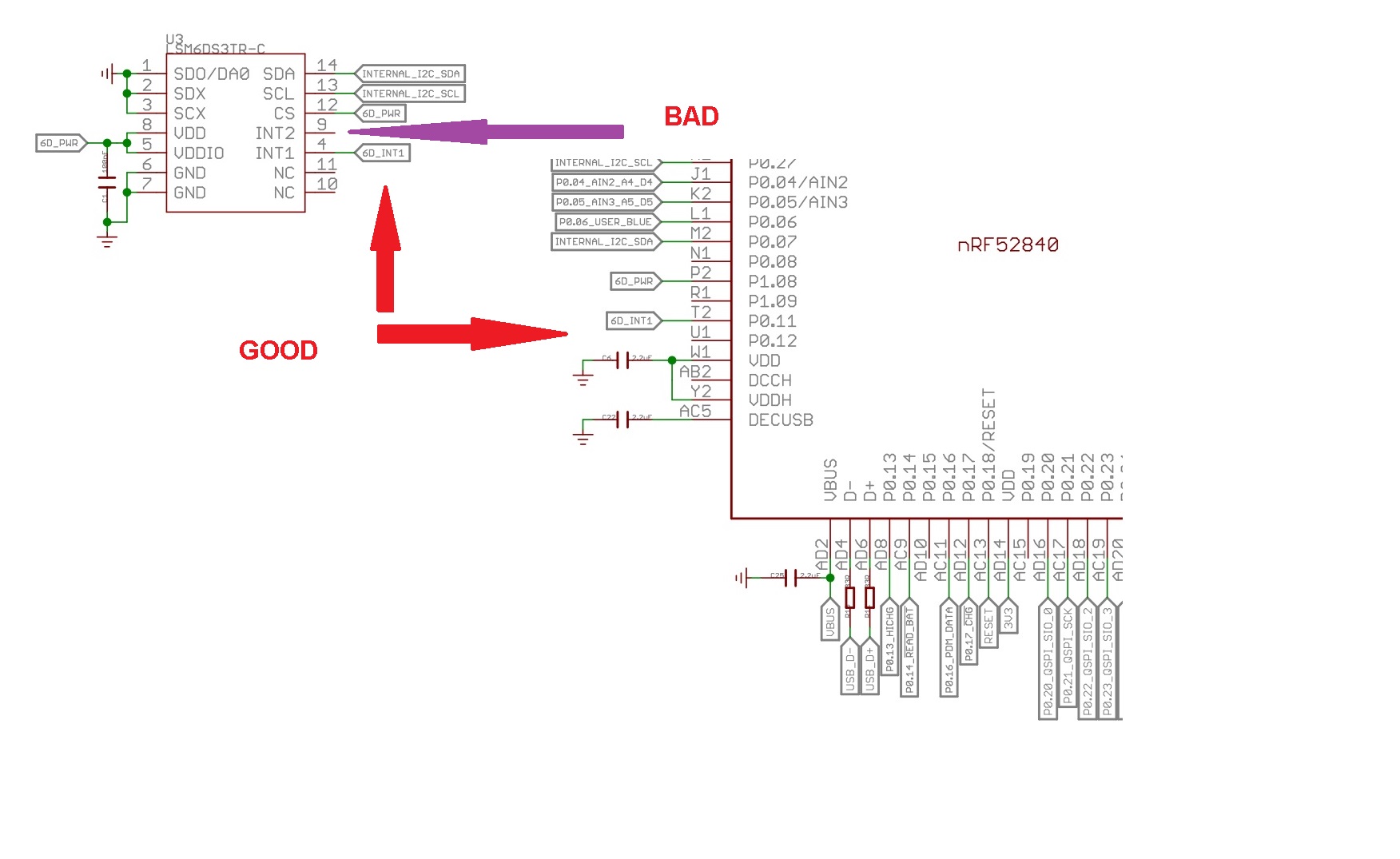
Do you know if the LM6DS3TR_C_INT2 pin is connected anywhere? It’s not defined in Seeed Xiao non-Mbed 1.0.0 firmware. It seems to be needed for the “Absolute Wrist Tilt” embedded low power feature to generate an interrupt.
I believe tilt detection and Absolute Wrist Tilt are the two low-power interrupt functions that can use the low-power ODRs of the accelerometer, while others like double tap might use up more power. The accelerometer in high performance mode uses 160 μA, while the low-power mode uses 9 μA.
A_IddHP
Accelerometer current
consumption
in high-performance mode
ODR < 1.6 kHz
ODR ≥ 1.6 kHz
150
160 μA
LA_IddNM Accelerometer current
consumption in normal mode ODR = 208 Hz 85 μA
LA_IddLM Accelerometer current
consumption in low-power mode ODR = 12.5 Hz 9 μA
iNEMO inertial module: always-on 3D accelerometer and 3D gyroscope (st.com)
@PJ_Glasso
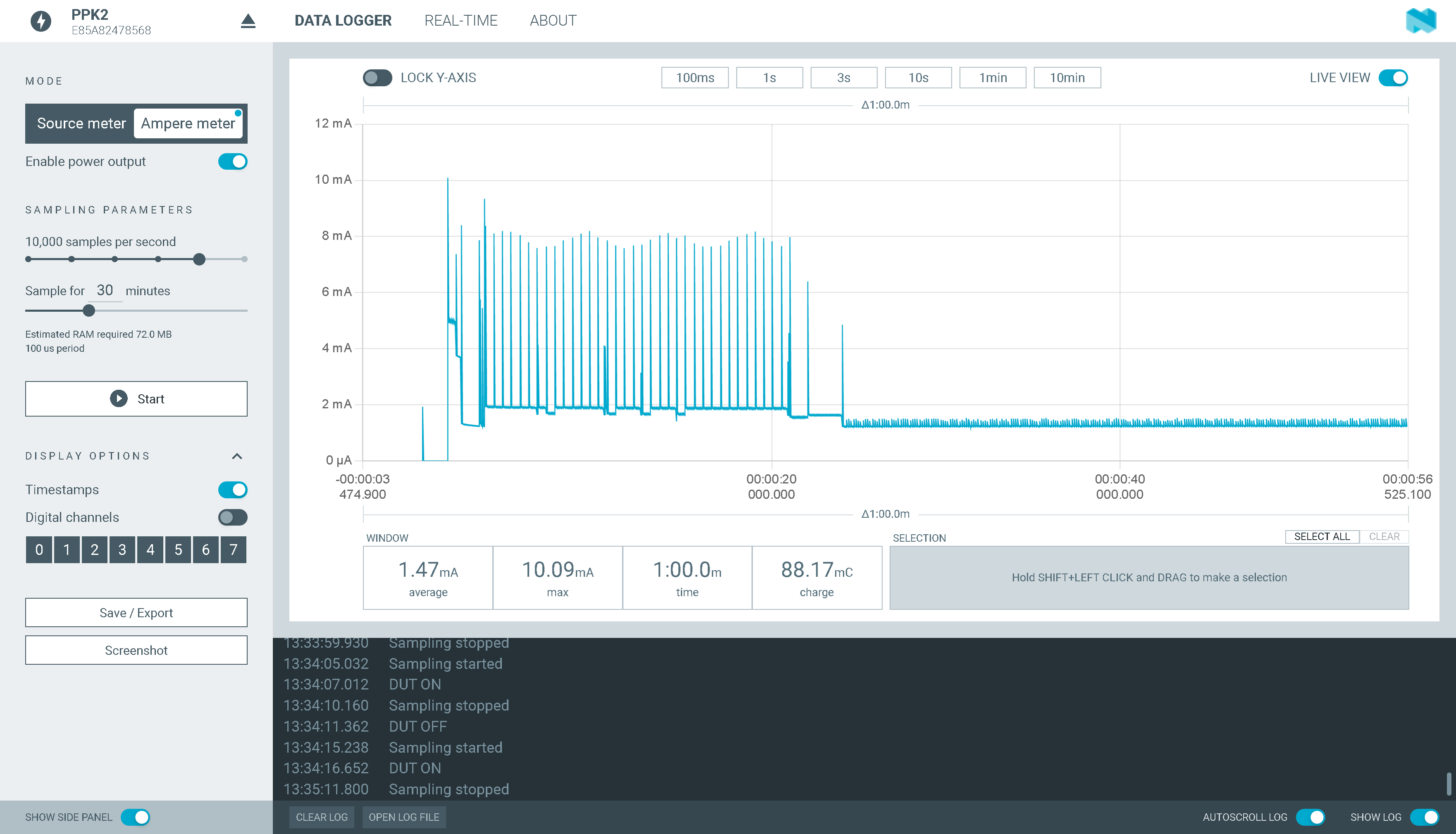
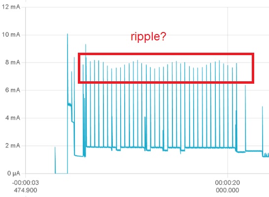
Do you notice that whenever you measure with PPK2, there is always a ripple superimposed on the current waveform? Could you measure with a resistor and see if it still exists?
It’s a issue with the over sampling with the PPK2 I always use the extra GND from the logic port to the GND of the chip(xiao), FWIW. Nordic forums has some topics about the PPK2, just lower the number of samples and go again.
Were you able to use a TILT interupt , if so how, did you write the registers directly? I guess too many Libs for the IMU, last count there’s at least 3. ?
Fun stuff… ![]()
HTH
GL ![]()
I guess the absolute wrist tilt function won’t work then!
I wrote the registers using lines like myIMU.writeRegister(LSM6DS3_ACC_GYRO_CTRL10_C, B10001100); //enable wrist tilt algorithm, following the datasheet .
I replaced the IMU interrupt with a SignalQuest SQ-SEN-815B tilt sensor that is zero power when not activated and 50uA when activated. It can be soldered directly to two pins spaced 3 holes apart on the Xiao, one of which is ground, and wakes with your interrupt sense pin pulldown code.
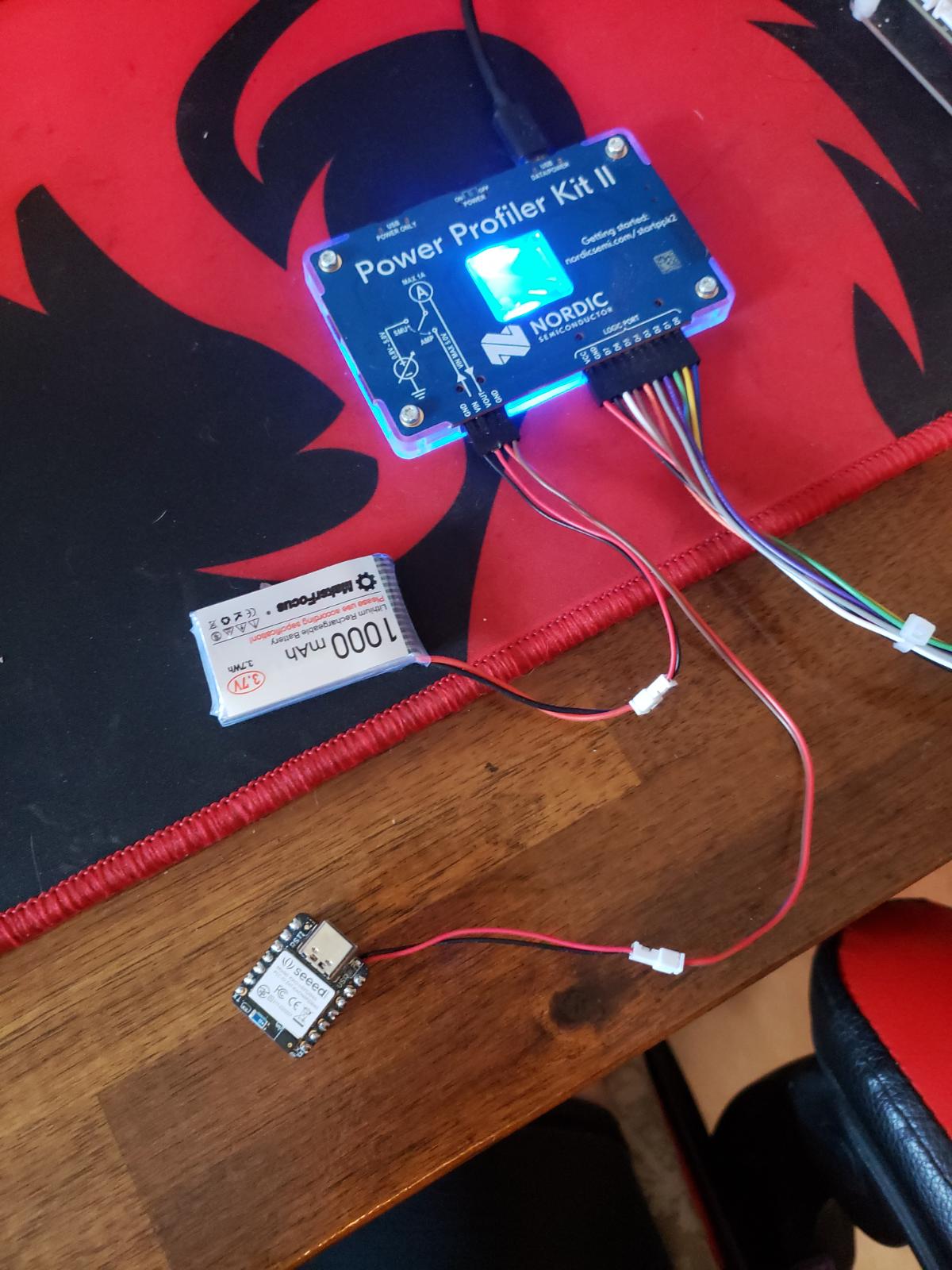
Even with this the Xiao BLE Sense still seems to kill the 95mAh battery in a day while in deep sleep, so I ordered a Nordic PPK2 to check why. It might be because of a Neopixel that I am sinking through the device. I wonder if the IMU and microphone take up a lot of power when they aren’t even initiated in the code?
Hi there,
Yes the PPK2 is worth the hondo for sure, hepled me shave allot of power wasting in y code, I’m goona have a look at the IMU data sheett and see what else is possible. Amazingly short sighted on Seeed Engineering’s part to leave such capabilities on the floor.
HTH
GL ![]()
What’s Your opinion ?
- can I replace PPK2 with oscilloscope + small resistor ? how small ?
Thanks for advice.
PPK2 is pretty expensive
Hi AdamM68,
Information about ppk2 can be found here. Schematics and manuals are included.
I got it and it is a very well designed and reliable unit.
I may be wrong about the absolute wrist tilt function not being usable.
I found a register that reroutes INT2 interrupts to the INT1 pad.
CTRL4_C (13h)
INT2_on_INT1 All interrupt signals available on INT1 pad enable. Default value: 0
(0: interrupt signals divided between INT1 and INT2 pads;
1: all interrupt signals in logic or on INT1 pad)
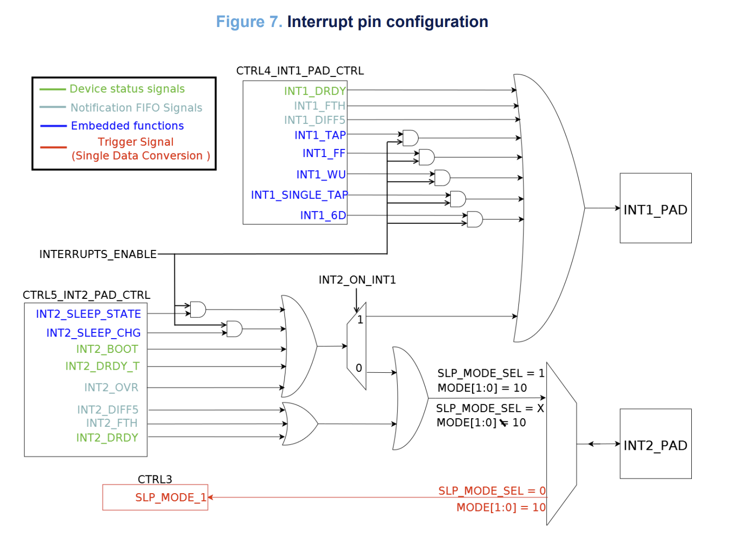
Here is a schematic from another STM accelerometer that roughly shows how it works:
Hi AdamM68,
You may be able to use an O-scope and some trickery but for what it does, NO. Being able to Source the Supply and vary it as well as the Amp meter mode to test actual battery drain. IMO one of nordics best tools, better than there dev boards (kitchen Sink) Easy to use and setup , being able to screen capture and real time display. It’s a tool and as others have indicated built and works VERY well Best $99 dollars I have spent to date. I have a DSS O-scope and it even beats that IMO,
HTH
GL ![]()
Hi Honvi,
Wow, Nice that would be great… NICE find. I’ll try to look into that , I’m using the Free-fall with Impact detection registers as well as motion detection along with double tap interrupts and it all works together well. I would really like to use the interrupts for all of it though. I’m currently at NAB 2023 so won’t know until I’m back this weekend.
cheers
HTH
GL ![]()
Just for all the noobs (like me) who are trying this code (since the documentation is low on this case). Note that the constants for the LEDs are named differently now (at least in my case). If you get errors that LEDR etc. can’t be found, they have to be renamed to LED_RED etc.
This is the code that worked for me.
/*****************************************************************************/
// IMU Interrupt Example for XIAO BLE Sense
// This example shows how to configure LMSD6S3TR-C on XIAO BLE SENSE to interrupt
// on INT1 after a "Double Tap" was recognized.
// Additionally, the device goes into System OFF state, after 5 interrupts were
// received. Another "Double Tap" will wake up the device again.
//
// by chuck
/*******************************************************************************/

#include "LSM6DS3.h"
#include "Wire.h"

LSM6DS3 myIMU(I2C_MODE, 0x6A);
#define int1Pin PIN_LSM6DS3TR_C_INT1

uint8_t interruptCount = 0; // Amount of received interrupts
uint8_t prevInterruptCount = 0; // Interrupt Counter from last loop

void setup() {
    Serial.begin(9600);

    pinMode(LED_RED, OUTPUT);
    pinMode(LED_GREEN, OUTPUT);
    pinMode(LED_BLUE, OUTPUT);
    setLedRGB(false, false, true); // set blue led

    myIMU.settings.gyroEnabled = 0; // Gyro currently not used, disabled to save power
    if (myIMU.begin() != 0) {
        Serial.println("IMU error");
    } else {
        Serial.println("IMU OK!");
    }

    setupDoubleTapInterrupt();

    pinMode(int1Pin, INPUT);
    attachInterrupt(digitalPinToInterrupt(int1Pin), int1ISR, RISING);
}

void loop() {
    setLedRGB(false, false, true); // reset led to blue only

    Serial.print("\Iterrupt Counter: ");
    Serial.println(interruptCount);

    // if interrupt was received in this cycle
    if (interruptCount > prevInterruptCount) {
      Serial.println("\Interrupt received!");
      setLedRGB(false, true, false); // set green only
    }

    prevInterruptCount = interruptCount;

    if (interruptCount >= 5) {
      // Trigger System OFF after 5 interrupts
      goToPowerOff();
    }

    delay(500);
}


// -------------------- System ------------------------- //

void goToPowerOff() {
  setLedRGB(false, false, false);
  Serial.println("Going to System OFF");
  setupDoubleTapInterrupt(); // not needed here, if already applied..
  delay(100); // delay seems important to apply settings, before going to System OFF
  //Ensure interrupt pin from IMU is set to wake up device
  nrf_gpio_cfg_sense_input(digitalPinToInterrupt(int1Pin), NRF_GPIO_PIN_PULLDOWN, NRF_GPIO_PIN_SENSE_HIGH);
  // Trigger System OFF
  NRF_POWER->SYSTEMOFF = 1;
}

// -------------------- Interrupts ------------------------- //

void setupDoubleTapInterrupt() {
  uint8_t error = 0;
  uint8_t dataToWrite = 0;

  // Double Tap Config
  myIMU.writeRegister(LSM6DS3_ACC_GYRO_CTRL1_XL, 0x60);
  myIMU.writeRegister(LSM6DS3_ACC_GYRO_TAP_CFG1, 0x8E);// INTERRUPTS_ENABLE, SLOPE_FDS
  myIMU.writeRegister(LSM6DS3_ACC_GYRO_TAP_THS_6D, 0x8C);
  myIMU.writeRegister(LSM6DS3_ACC_GYRO_INT_DUR2, 0x7F);
  myIMU.writeRegister(LSM6DS3_ACC_GYRO_WAKE_UP_THS, 0x80);
  myIMU.writeRegister(LSM6DS3_ACC_GYRO_MD1_CFG, 0x08);
}

void int1ISR()
{
  interruptCount++;
}

// -------------------- Utilities ------------------------- //

void setLedRGB(bool red, bool green, bool blue) {
  if (!blue) { digitalWrite(LED_BLUE, HIGH); } else { digitalWrite(LED_BLUE, LOW); }
  if (!green) { digitalWrite(LED_GREEN, HIGH); } else { digitalWrite(LED_GREEN, LOW); }
  if (!red) { digitalWrite(LED_RED, HIGH); } else { digitalWrite(LED_RED, LOW); }
}
In any case, thanks a lot for the code. I was looking for a free-fall detection and couldn’t find any working code. I hope yours will help me develop something I need.
Hi there, This One is working.
HTH
GL ![]()
Hey @PJ_Glasso! I realize this post is many moons old by now, but I was wondering if you had any insight as to why your “double-tap to wake/sleep” code works for the mbed-enabled board version (Seeed NRF52 mbed-enabled Boards, v2.9.0) but not the non-mbed version (I’m using Seeed NRF52 Boards v1.1.8)?
For context, when running on the non-mbed board version, double-tapping increments the interrupt counter, and the board ostensibly enters a power-off state momentarily, only to re-awake immediately. (This is even when including the delay as suggested.) Any suggestions on where to start if I wanted to adapt your code to non-mbed?
It’s my understanding that Seeed themselves recommend the mbed-enabled board versions when doing more advanced work with the IMU, but I’ve also heard that this choice can lead to headaches down the road due to poorer documentation than the Adafruit board library.
Apologies also if I’m asking the wrong questions–it’s probably clear that I’m new to this stuff, haha. Thanks in advance!
Hi there,
Yep roll back the board support package , the 2.9.1 doesn’t work
If you follow the threads you’ll see more.
Always, when-ever a known demo that should work, doesn’t, it’s always the BSP , LOL
that breaks them.
I prefer the mbed , but the power savings is way better if you use non-mbed.
Seeed needs to circle this square.
HTH
GL ![]() PJ
PJ
Any working code for deep sleep with Ble and is it possible A capacitive sensor act as a power button to turn on/off the device with a few seconds of hold. The device enter to sleep/deep sleep mode when idle and able to be woken up when the USB is plugged in, and a certain sequence of tapping on the capacitive sensor is completed.
Hi there,
There is. The Sleep demo with Tap to wake interrupt could be shoe-horned into that easy.
HTH
GL ![]() PJ
PJ
/*/

// IMU Interrupt Example for XIAO BLE Sense

// This example shows how to configure LMSD6S3TR-C on XIAO BLE SENSE to interrupt

// on INT1 after a "Double Tap" was recognized.

// Additionally, the device goes into System OFF state, after 5 interrupts were

// received. Another "Double Tap" will wake up the device again.

//

// Original by chuck

//poatched and toasted by pjg

/*/

#include "LSM6DS3.h"

#include "Wire.h"

#include <U8x8lib.h>

LSM6DS3 myIMU(I2C_MODE, 0x6A); // IMU

#define int1Pin 2

U8X8_SSD1306_128X64_NONAME_HW_I2C u8x8(/* clock=/ PIN_WIRE_SCL, / data=/ PIN_WIRE_SDA, / reset=*/ U8X8_PIN_NONE);

 // OLEDs without Reset of the Display

const int buttonPin = 1;     // the number of the pushbutton pin

int buttonState = 0;         // variable for reading the pushbutton status

int BuzzerPin = A3;

uint8_t interruptCount = 0; // Amount of received interrupts

uint8_t prevInterruptCount = 0; // Interrupt Counter from last loop

void setup() {

    Serial.begin(9600);

    delay(1000); //relax...

    Serial.println("Processor came out of reset.\n");

    u8x8.begin();

    u8x8.setFlipMode(1);   // set number from 1 to 3, the screen word will rotary 180


    pinMode(LED_BUILTIN, OUTPUT);// initialize the LED pin as an output:

    pinMode(buttonPin, INPUT_PULLUP);// initialize the pushbutton pin as an input:

    pinMode(BuzzerPin, OUTPUT);

    pinMode(LEDR, OUTPUT);

    pinMode(LEDG, OUTPUT);

    pinMode(LEDB, OUTPUT);

    setLedRGB(false, false, true); // set blue led

    myIMU.settings.gyroEnabled = 0; // Gyro currently not used, disabled to save power

    if (myIMU.begin() != 0) {

        Serial.println("IMU error");

    } else {

        Serial.println("IMU OK!");

    }


    setupDoubleTapInterrupt();


    pinMode(int1Pin, INPUT);

    attachInterrupt(digitalPinToInterrupt(int1Pin), int1ISR, RISING);

    u8x8.setFont(u8x8_font_8x13B_1x2_r);

    u8x8.clearDisplay();

    u8x8.setCursor(0, 0);

    u8x8.print("Tap Demo");


}

void loop() {

    setLedRGB(false, false, true); // reset led to blue only

    u8x8.setCursor(0, 3);

    u8x8.print(interruptCount);

    Serial.print("\Iterrupt Counter: ");

    Serial.println(interruptCount);

    // if interrupt was received in this cycle

    if (interruptCount > prevInterruptCount) {

      Serial.println("\Interrupt received!");

      setLedRGB(false, true, false); // set green only

    }


    prevInterruptCount = interruptCount;


    if (interruptCount >= 5) {

      // Trigger System OFF after 5 interrupts

      goToPowerOff();

    }


    delay(500);

}

// -------------------- System ------------------------- //

void goToPowerOff() {

  setLedRGB(false, false, false);

  Serial.println("Going to System OFF");

  u8x8.clearDisplay();

  u8x8.setCursor(0, 3);

  u8x8.print("SLEEP");

  setupDoubleTapInterrupt(); // not needed here, if already applied..

  delay(1000); // delay seems important to apply settings, before going to System OFF

  //Ensure interrupt pin from IMU is set to wake up device

  nrf_gpio_cfg_sense_input(digitalPinToInterrupt(int1Pin), NRF_GPIO_PIN_PULLDOWN, NRF_GPIO_PIN_SENSE_HIGH);

  // Trigger System OFF

  NRF_POWER->SYSTEMOFF = 1;

}

// -------------------- Interrupts ------------------------- //

void setupDoubleTapInterrupt() {

  uint8_t error = 0;

  uint8_t dataToWrite = 0;

  // Double Tap Config

  myIMU.writeRegister(LSM6DS3_ACC_GYRO_CTRL1_XL, 0x60); //* Acc = 416Hz (High-Performance mode)// Turn on the accelerometer

  // ODR_XL = 416 Hz, FS_XL = 2g

  myIMU.writeRegister(LSM6DS3_ACC_GYRO_TAP_CFG1, 0x8E);// INTERRUPTS_ENABLE, SLOPE_FDS// Enable interrupts and tap detection on X, Y, Z-axis

  myIMU.writeRegister(LSM6DS3_ACC_GYRO_TAP_THS_6D, 0x85);// Set tap threshold 8C

  myIMU.writeRegister(LSM6DS3_ACC_GYRO_INT_DUR2, 0x7F);// Set Duration, Quiet and Shock time windows 7F

  myIMU.writeRegister(LSM6DS3_ACC_GYRO_WAKE_UP_THS, 0x80);// Single & double-tap enabled (SINGLE_DOUBLE_TAP = 1)

  myIMU.writeRegister(LSM6DS3_ACC_GYRO_MD1_CFG, 0x08);// Double-tap interrupt driven to INT1 pin

}

void int1ISR()

{

  interruptCount++;

 ;


}

// -------------------- Utilities ------------------------- //

void setLedRGB(bool red, bool green, bool blue) {

  if (!blue) { digitalWrite(LEDB, HIGH); } else { digitalWrite(LEDB, LOW); }

  if (!green) { digitalWrite(LEDG, HIGH); } else { digitalWrite(LEDG, LOW); }

  if (!red) { digitalWrite(LEDR, HIGH); } else { digitalWrite(LEDR, LOW); }

}
This code working i tested with pin2. Is it posible to detect usb power?