Hi there,
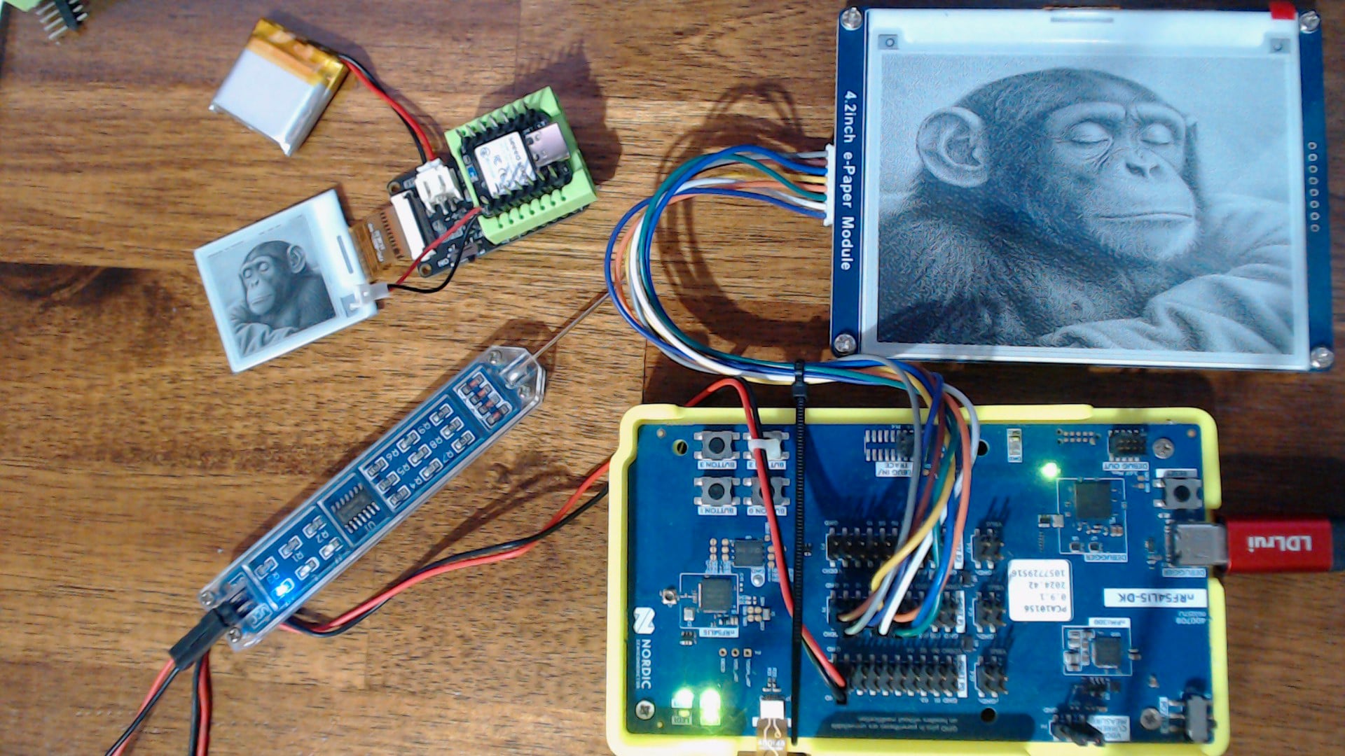
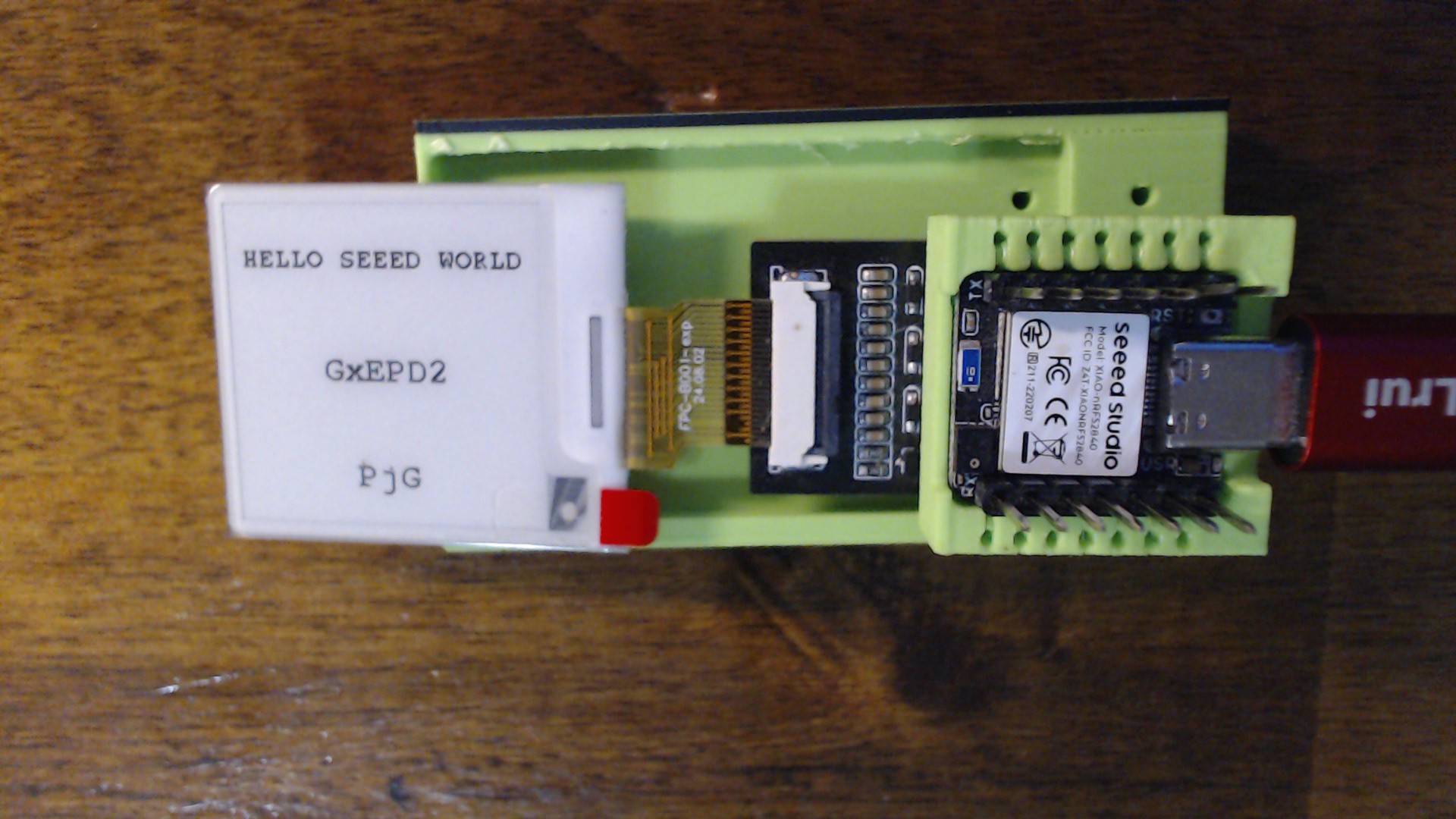
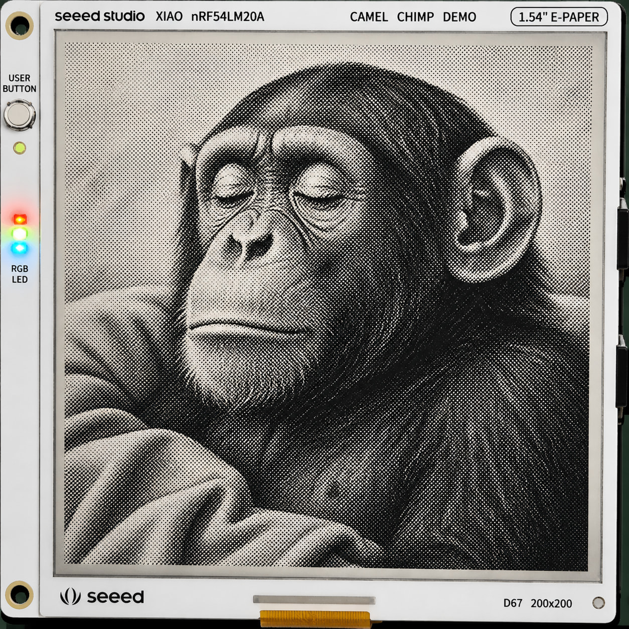
SO the E-Paper is getting better every year, more support for the partial refresh and the speed of the display updates is very reasonable and fast.
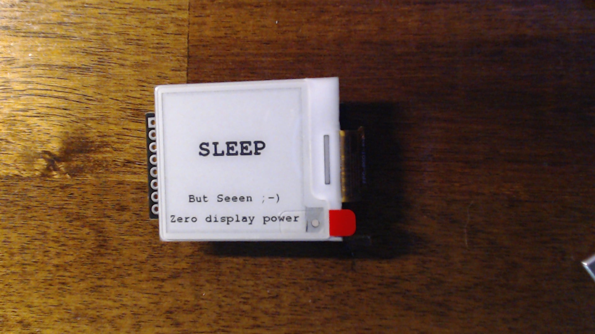
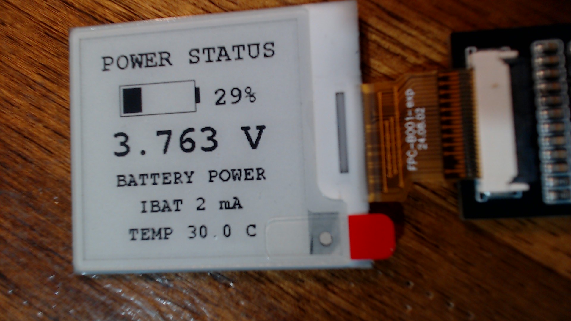
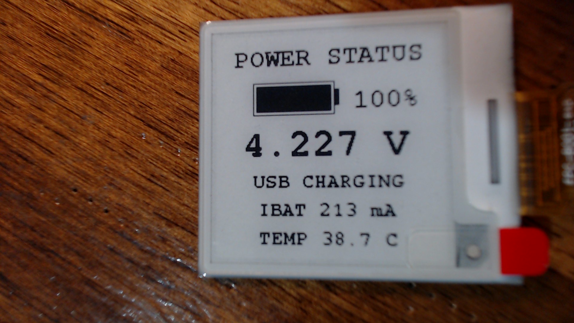
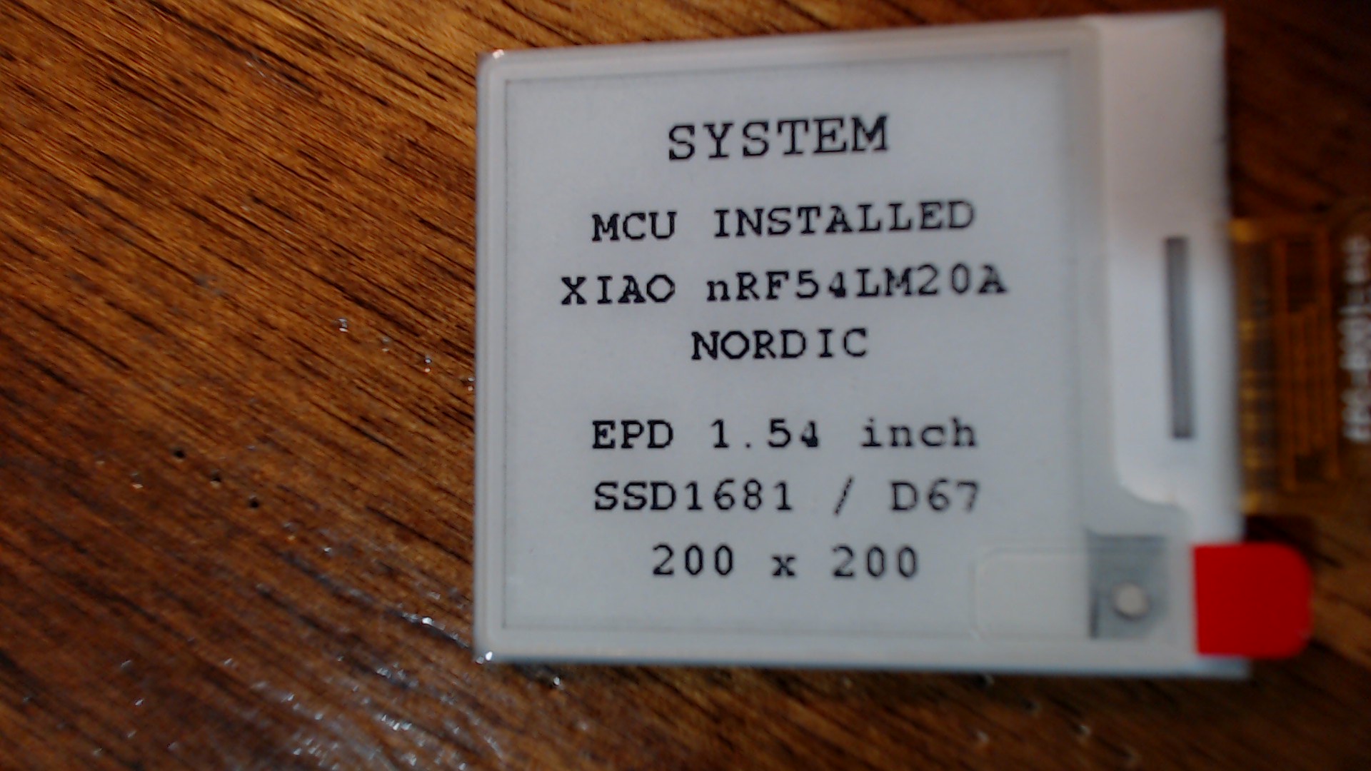
This video demonstrates the code that is included and this thread will be expanded to include the nRF54L15A and the New nRF54LM20A Xiao family MCU’s the Newest unit should get us even lower Sleep current numbers with it’s PMIC new design.
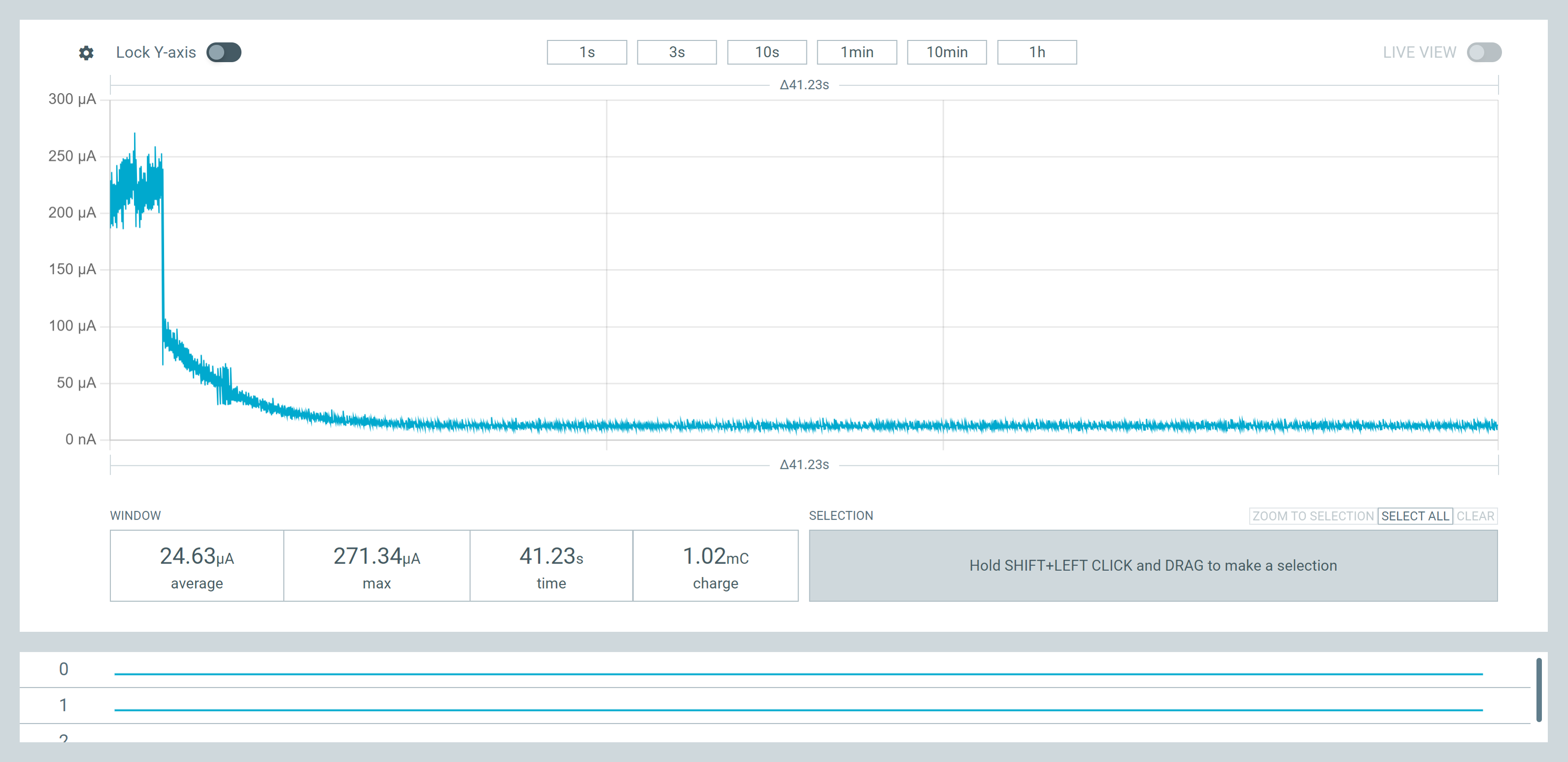
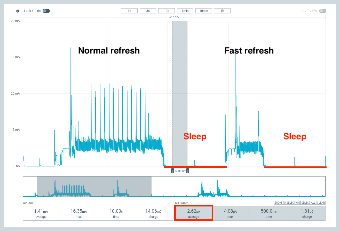
9-12 uA. Sleep current baseline for the nRF52840 parts.. The code has a few of the obvious power down items and is compliable for both BSP’s 1.1.3 and 2.9.3.
note: I choose the non-embed for For PPK II low-power testing, use Seeed nRF52 Boards 1.1.13 as your primary benchmark.
It is the better choice here because it has less framework overhead than the mbed core and gives more direct, predictable control over the nRF52840 hardware. The mbed 2.9.3 package brings a larger runtime, USB serial infrastructure, RTOS/ticker activity, and more background initialization, which makes it harder to determine whether a high sleep current comes from your sketch or the core.
- Hibernate the SSD1681.
- Perform the RGB signoff
- Check the PPKII for values.
HTH
GL  PJ
PJ 
/***************************************************************************
 *
 *  WINNER WINNER... MICROAMP DINNER!
 *
 *  XIAO nRF52840 Sense
 *  1.54-inch SSD1681 / D67 E-Paper Demonstration
 *
 *  GOLD STANDARD / MASTER ARCHIVE BUILD
 *
 *  Primary BSP:
 *      Seeed nRF52 Boards 1.1.13
 *
 *  Also compatible with:
 *      Seeeduino mbed-enabled Boards 2.9.3
 *
 *  Tested final System OFF current:
 *      Approximately 9.99 µA
 *
 *  Test equipment:
 *      Nordic Power Profiler Kit II
 *
 *  Test configuration:
 *      XIAO powered only from the PPK II
 *      No USB cable connected during the power measurement
 *      Complete XIAO Sense + e-paper breakout assembly measured
 *
 ***************************************************************************
 *
 *  HARDWARE
 *
 *      MCU:
 *          Seeed Studio XIAO nRF52840 Sense
 *
 *      Display:
 *          1.54-inch monochrome e-paper
 *
 *      Resolution:
 *          200 × 200 pixels
 *
 *      Controller:
 *          SSD1681
 *
 *      GxEPD2 panel class:
 *          GxEPD2_154_D67
 *
 ***************************************************************************
 *
 *  E-PAPER CONNECTIONS
 *
 *      E-paper RST   -> XIAO D0
 *      E-paper CS    -> XIAO D1
 *      E-paper DC    -> XIAO D3
 *      E-paper BUSY  -> XIAO D5
 *      E-paper SCK   -> XIAO D8
 *      E-paper MOSI  -> XIAO D10
 *      E-paper VCC   -> XIAO 3V3
 *      E-paper GND   -> XIAO GND
 *
 *  The display is write-only for this demonstration.
 *  MISO is not required.
 *
 ***************************************************************************
 *
 *  DEMONSTRATION SEQUENCE
 *
 *      1. Initialize the SSD1681 e-paper display.
 *
 *      2. Clear the panel to white.
 *
 *      3. Show the system-information screen:
 *
 *             SYSTEM
 *             MCU INSTALLED
 *             XIAO nRF52840
 *             SENSE
 *             EPD 1.54 inch
 *             SSD1681 / D67
 *             200 x 200
 *
 *      4. Show the HELLO SEEED WORLD screen.
 *
 *      5. Perform a 30-count partial-refresh countdown.
 *
 *      6. Show the GOING TO SLEEP screen.
 *
 *      7. Perform a flashing 10-count partial-refresh countdown.
 *
 *      8. Show the final retained SLEEP screen.
 *
 *      9. Put the SSD1681 controller into hibernate.
 *
 *     10. Perform the visible RGB signoff:
 *
 *             RED
 *             WHITE
 *             BLUE
 *
 *     11. Turn off the onboard IMU supply.
 *
 *     12. Stop the e-paper SPI interface.
 *
 *     13. Force the active-low RGB LED fully off.
 *
 *     14. Enter nRF52840 System OFF.
 *
 *  The final e-paper image remains visible without continuous display power.
 *
 ***************************************************************************
 *
 *  LOW-POWER DESIGN NOTES
 *
 *  This master build intentionally uses a minimal shutdown path.
 *
 *  The nRF52840 automatically shuts down its internal peripherals when
 *  System OFF is entered successfully. Manually disabling every timer,
 *  interrupt, UART, USB block, clock and peripheral was found to introduce
 *  additional failure modes and was not required.
 *
 *  The final shutdown therefore handles only the external hardware states
 *  that matter:
 *
 *      - SSD1681 hibernate
 *      - e-paper interface pins
 *      - onboard IMU power
 *      - microphone-related pins
 *      - battery-measurement control pin
 *      - onboard RGB LED
 *      - MCU System OFF
 *
 ***************************************************************************
 *
 *  ONBOARD QSPI FLASH NOTE
 *
 *  The XIAO nRF52840 Sense includes onboard QSPI flash.
 *
 *  A direct custom-instruction experiment was previously used to send the
 *  flash command:
 *
 *      0xB9 = Deep Power-Down
 *
 *  Although the command appeared to execute, manipulating the QSPI peripheral
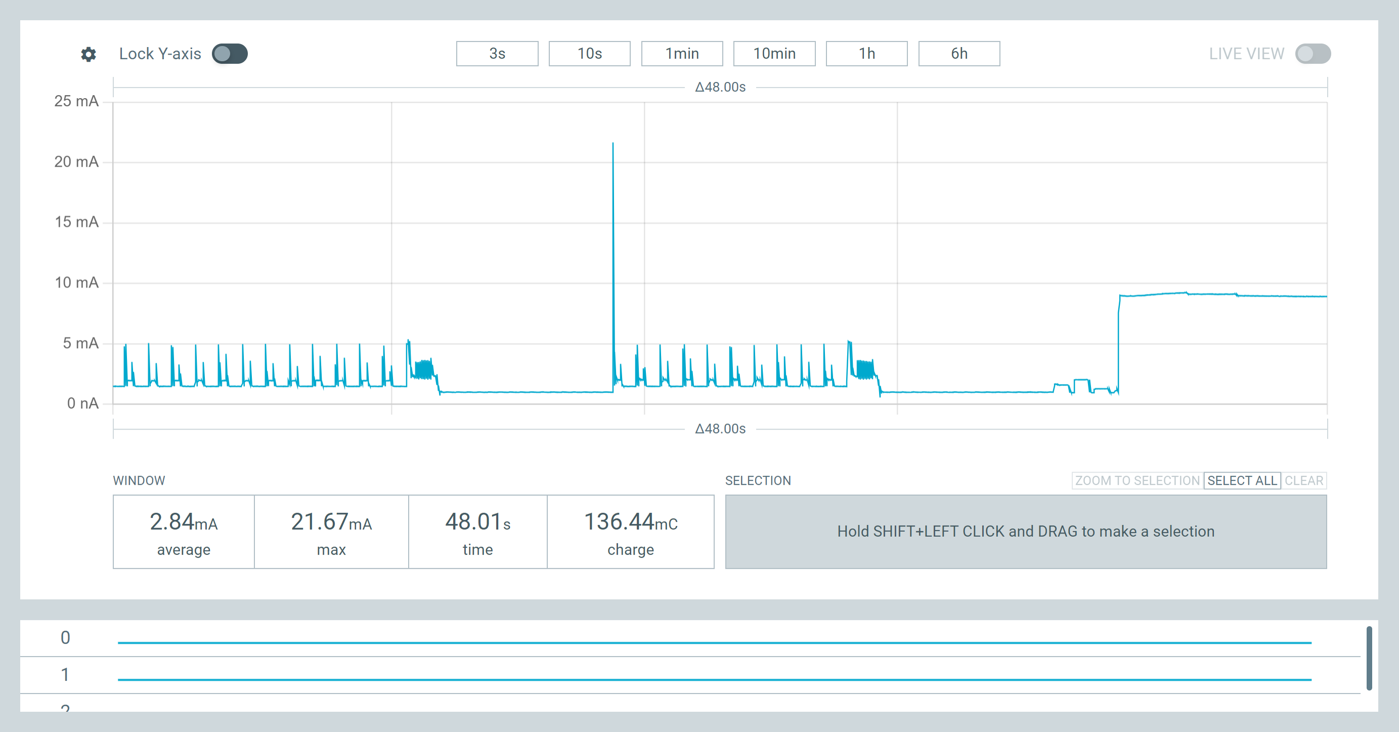
 *  during final shutdown caused the tested assembly to remain near 9–18 mA
 *  instead of entering the expected microamp System OFF state.
 *
 *  The QSPI flash deep-power-down routine is therefore deliberately omitted
 *  from this gold-standard build.
 *
 *  Leaving the onboard flash untouched produced the proven approximately
 *  9.99 µA final measurement.
 *
 ***************************************************************************
 *
 *  WAKE BEHAVIOR
 *
 *  This sketch does not configure a GPIO wake source.
 *
 *  After entering System OFF, restart the board using:
 *
 *      - the XIAO RESET button, or
 *      - a complete power cycle
 *
 ***************************************************************************
 *
 *  REQUIRED ARDUINO LIBRARY
 *
 *      GxEPD2
 *
 *  Fonts used from the Adafruit GFX font collection included with GxEPD2:
 *
 *      FreeMonoBold9pt7b
 *      FreeMonoBold12pt7b
 *      FreeMonoBold18pt7b
 *      FreeMonoBold24pt7b
 *
 ***************************************************************************/

#include <Arduino.h>
#include <SPI.h>

#include <GxEPD2_BW.h>

#include <Fonts/FreeMonoBold9pt7b.h>
#include <Fonts/FreeMonoBold12pt7b.h>
#include <Fonts/FreeMonoBold18pt7b.h>
#include <Fonts/FreeMonoBold24pt7b.h>

#include <nrf.h>


/***************************************************************************
 *
 *  BSP SUPPORT
 *
 *  Primary:
 *      Seeed nRF52 Boards 1.1.13
 *
 *  Secondary compatibility:
 *      Seeeduino mbed-enabled Boards 2.9.3
 *
 ***************************************************************************/

#if defined(ARDUINO_ARCH_NRF52) && !defined(ARDUINO_ARCH_MBED)

#include <nrf_sdm.h>
#include <nrf_soc.h>

#define XIAO_BSP_SEEED_NRF52  1
#define XIAO_BSP_MBED         0

#elif defined(ARDUINO_ARCH_MBED)

#define XIAO_BSP_SEEED_NRF52  0
#define XIAO_BSP_MBED         1

#else

#error "Unsupported BSP. Select a Seeed XIAO nRF52840 Sense board."

#endif


/***************************************************************************
 *
 *  E-PAPER PIN ASSIGNMENTS
 *
 ***************************************************************************/

#define EPD_RST   D0
#define EPD_CS    D1
#define EPD_DC    D3
#define EPD_BUSY  D5

#define EPD_SCK   D8
#define EPD_MOSI  D10


/***************************************************************************
 *
 *  XIAO nRF52840 SENSE HARDWARE
 *
 *  IMU power:
 *      P1.08
 *
 *  PDM microphone:
 *      DATA = P0.16
 *      CLK  = P1.00
 *
 *  Battery measurement control:
 *      P0.14
 *
 ***************************************************************************/

constexpr uint32_t IMU_POWER_PORT = 1;
constexpr uint32_t IMU_POWER_PIN  = 8;

constexpr uint32_t MIC_DATA_PORT = 0;
constexpr uint32_t MIC_DATA_PIN  = 16;

constexpr uint32_t MIC_CLOCK_PORT = 1;
constexpr uint32_t MIC_CLOCK_PIN  = 0;

constexpr uint32_t BATTERY_CONTROL_PORT = 0;
constexpr uint32_t BATTERY_CONTROL_PIN  = 14;


/***************************************************************************
 *
 *  DISPLAY INSTANCE
 *
 ***************************************************************************/

GxEPD2_BW<GxEPD2_154_D67, GxEPD2_154_D67::HEIGHT> display(
  GxEPD2_154_D67(
    EPD_CS,
    EPD_DC,
    EPD_RST,
    EPD_BUSY
  )
);


/***************************************************************************
 *
 *  DEMONSTRATION TIMING
 *
 ***************************************************************************/

/*
 * Extra viewing time after each full refresh.
 *
 * GxEPD2 already waits for the controller BUSY signal internally.
 * These delays are included to make the video demonstration easy to follow.
 */
constexpr uint32_t FULL_SCREEN_VIEW_TIME_MS = 2000;

/*
 * Time between partial-refresh countdown updates.
 */
constexpr uint32_t PARTIAL_UPDATE_PAUSE_MS = 900;

/*
 * RGB signoff timing.
 */
constexpr uint32_t RGB_ON_TIME_MS  = 600;
constexpr uint32_t RGB_OFF_TIME_MS = 200;


/***************************************************************************
 *
 *  COUNTDOWN SETTINGS
 *
 ***************************************************************************/

constexpr uint8_t HELLO_COUNT_START = 30;
constexpr uint8_t SLEEP_COUNT_START = 10;


/***************************************************************************
 *
 *  PARTIAL UPDATE WINDOWS
 *
 *  Coordinates are based on display rotation 1.
 *
 ***************************************************************************/

constexpr int16_t HELLO_COUNTER_X = 48;
constexpr int16_t HELLO_COUNTER_Y = 70;
constexpr int16_t HELLO_COUNTER_W = 104;
constexpr int16_t HELLO_COUNTER_H = 70;

constexpr int16_t SLEEP_COUNTER_X = 48;
constexpr int16_t SLEEP_COUNTER_Y = 82;
constexpr int16_t SLEEP_COUNTER_W = 104;
constexpr int16_t SLEEP_COUNTER_H = 72;


/***************************************************************************
 *
 *  CENTERED TEXT HELPERS
 *
 ***************************************************************************/

/*
 * Print text centered horizontally using a specified text baseline.
 */
void printCentered(
  const char* text,
  int16_t baselineY
)
{
  int16_t boundsX;
  int16_t boundsY;

  uint16_t boundsWidth;
  uint16_t boundsHeight;

  display.getTextBounds(
    text,
    0,
    baselineY,
    &boundsX,
    &boundsY,
    &boundsWidth,
    &boundsHeight
  );

  const int16_t cursorX =
    ((int16_t)display.width() - (int16_t)boundsWidth) / 2 -
    boundsX;

  display.setCursor(
    cursorX,
    baselineY
  );

  display.print(text);
}


/*
 * Print text centered both horizontally and vertically inside a rectangular
 * partial-update window.
 */
void printCenteredInWindow(
  const char* text,
  int16_t windowX,
  int16_t windowY,
  int16_t windowWidth,
  int16_t windowHeight
)
{
  int16_t boundsX;
  int16_t boundsY;

  uint16_t boundsWidth;
  uint16_t boundsHeight;

  display.getTextBounds(
    text,
    0,
    0,
    &boundsX,
    &boundsY,
    &boundsWidth,
    &boundsHeight
  );

  const int16_t cursorX =
    windowX +
    ((windowWidth - (int16_t)boundsWidth) / 2) -
    boundsX;

  const int16_t cursorY =
    windowY +
    ((windowHeight - (int16_t)boundsHeight) / 2) -
    boundsY;

  display.setCursor(
    cursorX,
    cursorY
  );

  display.print(text);
}


/***************************************************************************
 *
 *  ONBOARD RGB LED
 *
 *  The XIAO onboard RGB LED is active-low:
 *
 *      LOW  = LED on
 *      HIGH = LED off
 *
 ***************************************************************************/

void initializeRgbLed()
{
  pinMode(
    LED_RED,
    OUTPUT
  );

  pinMode(
    LED_GREEN,
    OUTPUT
  );

  pinMode(
    LED_BLUE,
    OUTPUT
  );

  digitalWrite(
    LED_RED,
    HIGH
  );

  digitalWrite(
    LED_GREEN,
    HIGH
  );

  digitalWrite(
    LED_BLUE,
    HIGH
  );
}


void rgbOff()
{
  digitalWrite(
    LED_RED,
    HIGH
  );

  digitalWrite(
    LED_GREEN,
    HIGH
  );

  digitalWrite(
    LED_BLUE,
    HIGH
  );
}


void showRgbColor(
  bool redOn,
  bool greenOn,
  bool blueOn
)
{
  digitalWrite(
    LED_RED,
    redOn ? LOW : HIGH
  );

  digitalWrite(
    LED_GREEN,
    greenOn ? LOW : HIGH
  );

  digitalWrite(
    LED_BLUE,
    blueOn ? LOW : HIGH
  );

  delay(
    RGB_ON_TIME_MS
  );

  rgbOff();

  delay(
    RGB_OFF_TIME_MS
  );
}


/*
 * Visible signoff before the board enters System OFF.
 *
 * Sequence:
 *
 *      RED
 *      WHITE
 *      BLUE
 */
void playFinalRgbSequence()
{
  showRgbColor(
    true,
    false,
    false
  );

  showRgbColor(
    true,
    true,
    true
  );

  showRgbColor(
    false,
    false,
    true
  );

  rgbOff();
}


/***************************************************************************
 *
 *  SCREEN 1
 *
 *  SYSTEM INFORMATION
 *
 ***************************************************************************/

void showStartupScreen()
{
  display.setRotation(1);
  display.setFullWindow();

  display.firstPage();

  do
  {
    display.fillScreen(
      GxEPD_WHITE
    );

    display.setTextColor(
      GxEPD_BLACK
    );

    display.setTextSize(1);

    display.setFont(
      &FreeMonoBold12pt7b
    );

    printCentered(
      "SYSTEM",
      28
    );

    display.setFont(
      &FreeMonoBold9pt7b
    );

    printCentered(
      "MCU INSTALLED",
      58
    );

    printCentered(
      "XIAO nRF52840",
      82
    );

    printCentered(
      "SENSE",
      104
    );

    printCentered(
      "EPD 1.54 inch",
      137
    );

    printCentered(
      "SSD1681 / D67",
      160
    );

    printCentered(
      "200 x 200",
      184
    );
  }
  while (
    display.nextPage()
  );
}


/***************************************************************************
 *
 *  SCREEN 2
 *
 *  HELLO SEEED WORLD
 *
 ***************************************************************************/

void showHelloScreen()
{
  display.setRotation(1);
  display.setFullWindow();

  display.firstPage();

  do
  {
    display.fillScreen(
      GxEPD_WHITE
    );

    display.setTextColor(
      GxEPD_BLACK
    );

    display.setTextSize(1);

    display.setFont(
      &FreeMonoBold9pt7b
    );

    printCentered(
      "HELLO SEEED WORLD",
      30
    );

    printCentered(
      "COUNTDOWN",
      62
    );

    display.setFont(
      &FreeMonoBold12pt7b
    );

    printCentered(
      "GxEPD2",
      164
    );

    display.setFont(
      &FreeMonoBold9pt7b
    );

    printCentered(
      "PjG",
      190
    );
  }
  while (
    display.nextPage()
  );
}


/***************************************************************************
 *
 *  HELLO SCREEN PARTIAL UPDATE
 *
 ***************************************************************************/

void updateHelloCounter(
  uint8_t counterValue
)
{
  char counterText[8];

  snprintf(
    counterText,
    sizeof(counterText),
    "%u",
    counterValue
  );

  display.setRotation(1);

  display.setPartialWindow(
    HELLO_COUNTER_X,
    HELLO_COUNTER_Y,
    HELLO_COUNTER_W,
    HELLO_COUNTER_H
  );

  display.firstPage();

  do
  {
    display.fillScreen(
      GxEPD_WHITE
    );

    display.setTextColor(
      GxEPD_BLACK
    );

    display.setTextSize(1);

    display.setFont(
      &FreeMonoBold24pt7b
    );

    printCenteredInWindow(
      counterText,
      HELLO_COUNTER_X,
      HELLO_COUNTER_Y,
      HELLO_COUNTER_W,
      HELLO_COUNTER_H
    );
  }
  while (
    display.nextPage()
  );

  delay(
    PARTIAL_UPDATE_PAUSE_MS
  );
}


void runHelloCountdown()
{
  for (
    int16_t counterValue = HELLO_COUNT_START;
    counterValue >= 1;
    counterValue--
  )
  {
    updateHelloCounter(
      (uint8_t)counterValue
    );
  }
}


/***************************************************************************
 *
 *  SCREEN 3
 *
 *  GOING TO SLEEP
 *
 ***************************************************************************/

void showGoingToSleepScreen()
{
  display.setRotation(1);
  display.setFullWindow();

  display.firstPage();

  do
  {
    display.fillScreen(
      GxEPD_WHITE
    );

    display.setTextColor(
      GxEPD_BLACK
    );

    display.setTextSize(1);

    display.setFont(
      &FreeMonoBold12pt7b
    );

    printCentered(
      "GOING TO",
      32
    );

    printCentered(
      "SLEEP",
      60
    );

    display.setFont(
      &FreeMonoBold9pt7b
    );

    printCentered(
      "HIBERNATING IN",
      174
    );
  }
  while (
    display.nextPage()
  );
}


/***************************************************************************
 *
 *  SLEEP SCREEN FLASHING PARTIAL UPDATE
 *
 ***************************************************************************/

void updateFlashingSleepCounter(
  uint8_t counterValue,
  bool inverted
)
{
  char counterText[8];

  snprintf(
    counterText,
    sizeof(counterText),
    "%u",
    counterValue
  );

  display.setRotation(1);

  display.setPartialWindow(
    SLEEP_COUNTER_X,
    SLEEP_COUNTER_Y,
    SLEEP_COUNTER_W,
    SLEEP_COUNTER_H
  );

  display.firstPage();

  do
  {
    if (inverted)
    {
      display.fillScreen(
        GxEPD_BLACK
      );

      display.setTextColor(
        GxEPD_WHITE
      );
    }
    else
    {
      display.fillScreen(
        GxEPD_WHITE
      );

      display.setTextColor(
        GxEPD_BLACK
      );
    }

    display.setTextSize(1);

    display.setFont(
      &FreeMonoBold24pt7b
    );

    printCenteredInWindow(
      counterText,
      SLEEP_COUNTER_X,
      SLEEP_COUNTER_Y,
      SLEEP_COUNTER_W,
      SLEEP_COUNTER_H
    );
  }
  while (
    display.nextPage()
  );

  delay(
    PARTIAL_UPDATE_PAUSE_MS
  );
}


void runFlashingSleepCountdown()
{
  bool inverted = true;

  for (
    int16_t counterValue = SLEEP_COUNT_START;
    counterValue >= 1;
    counterValue--
  )
  {
    updateFlashingSleepCounter(
      (uint8_t)counterValue,
      inverted
    );

    inverted = !inverted;
  }
}


/***************************************************************************
 *
 *  FINAL RETAINED SCREEN
 *
 *  This image remains visible after:
 *
 *      - SSD1681 hibernate
 *      - MCU System OFF
 *      - display power consumption falls to essentially zero
 *
 ***************************************************************************/

void showFinalSleepScreen()
{
  display.setRotation(1);
  display.setFullWindow();

  display.firstPage();

  do
  {
    display.fillScreen(
      GxEPD_WHITE
    );

    display.setTextColor(
      GxEPD_BLACK
    );

    display.setTextSize(1);

    display.setFont(
      &FreeMonoBold18pt7b
    );

    printCentered(
      "SLEEP",
      90
    );

    display.setFont(
      &FreeMonoBold9pt7b
    );

    printCentered(
      "But Seeen ;-)",
      158
    );

    printCentered(
      "Zero display power",
      188
    );
  }
  while (
    display.nextPage()
  );
}


/***************************************************************************
 *
 *  GPIO LOW-POWER HELPER
 *
 *  Configures a physical nRF52840 pin as:
 *
 *      - input
 *      - input buffer disconnected
 *      - no pull resistor
 *      - GPIO sense disabled
 *
 ***************************************************************************/

void disconnectPhysicalPin(
  uint32_t port,
  uint32_t pin
)
{
  const uint32_t pinConfiguration =
    (
      GPIO_PIN_CNF_DIR_Input
      << GPIO_PIN_CNF_DIR_Pos
    ) |
    (
      GPIO_PIN_CNF_INPUT_Disconnect
      << GPIO_PIN_CNF_INPUT_Pos
    ) |
    (
      GPIO_PIN_CNF_PULL_Disabled
      << GPIO_PIN_CNF_PULL_Pos
    ) |
    (
      GPIO_PIN_CNF_DRIVE_S0S1
      << GPIO_PIN_CNF_DRIVE_Pos
    ) |
    (
      GPIO_PIN_CNF_SENSE_Disabled
      << GPIO_PIN_CNF_SENSE_Pos
    );

  if (
    port == 0 &&
    pin < 32
  )
  {
    NRF_P0->PIN_CNF[pin] =
      pinConfiguration;
  }
  else if (
    port == 1 &&
    pin < 16
  )
  {
    NRF_P1->PIN_CNF[pin] =
      pinConfiguration;
  }
}


/***************************************************************************
 *
 *  XIAO SENSE HARDWARE SHUTDOWN
 *
 ***************************************************************************/

void shutDownSenseHardware()
{
  /*
   * Turn off the onboard IMU supply.
   *
   * P1.08 is driven low.
   */
  NRF_P1->DIRSET =
    1UL << IMU_POWER_PIN;

  NRF_P1->OUTCLR =
    1UL << IMU_POWER_PIN;

  /*
   * Disconnect microphone pins.
   */
  disconnectPhysicalPin(
    MIC_DATA_PORT,
    MIC_DATA_PIN
  );

  disconnectPhysicalPin(
    MIC_CLOCK_PORT,
    MIC_CLOCK_PIN
  );

  /*
   * Disconnect the battery-measurement control pin.
   */
  disconnectPhysicalPin(
    BATTERY_CONTROL_PORT,
    BATTERY_CONTROL_PIN
  );
}


/***************************************************************************
 *
 *  E-PAPER INTERFACE SHUTDOWN
 *
 *  The SSD1681 must already be in hibernate before this function is called.
 *
 ***************************************************************************/

void shutDownEpaperInterface()
{
  /*
   * Stop the Arduino SPI interface.
   */
  SPI.end();

  /*
   * Keep e-paper chip select inactive.
   */
  pinMode(
    EPD_CS,
    OUTPUT
  );

  digitalWrite(
    EPD_CS,
    HIGH
  );

  /*
   * Leave the control lines in quiet, deterministic states.
   */
  pinMode(
    EPD_DC,
    OUTPUT
  );

  digitalWrite(
    EPD_DC,
    LOW
  );

  pinMode(
    EPD_RST,
    OUTPUT
  );

  digitalWrite(
    EPD_RST,
    HIGH
  );

  /*
   * Release the SPI clock, data and BUSY lines.
   */
  pinMode(
    EPD_SCK,
    INPUT
  );

  pinMode(
    EPD_MOSI,
    INPUT
  );

  pinMode(
    EPD_BUSY,
    INPUT
  );
}


/***************************************************************************
 *
 *  FINAL RGB OFF STATE
 *
 ***************************************************************************/

void forceRgbOff()
{
  /*
   * The onboard RGB LED is active-low.
   *
   * All three pins must remain HIGH to guarantee that no color remains on.
   */
  pinMode(
    LED_RED,
    OUTPUT
  );

  pinMode(
    LED_GREEN,
    OUTPUT
  );

  pinMode(
    LED_BLUE,
    OUTPUT
  );

  digitalWrite(
    LED_RED,
    HIGH
  );

  digitalWrite(
    LED_GREEN,
    HIGH
  );

  digitalWrite(
    LED_BLUE,
    HIGH
  );
}


/***************************************************************************
 *
 *  ENTER NRF52840 SYSTEM OFF
 *
 *  Primary BSP:
 *      Seeed nRF52 Boards 1.1.13
 *
 *  If a SoftDevice is active, the SoftDevice-safe API is used.
 *
 *  If no SoftDevice is active, or when compiling with the mbed BSP,
 *  System OFF is entered directly through NRF_POWER.
 *
 ***************************************************************************/

[[noreturn]] void enterSystemOff()
{
  /*
   * No Arduino framework calls should be made after the System OFF request.
   */

#if XIAO_BSP_SEEED_NRF52

  uint8_t softDeviceEnabled = 0;

  const uint32_t softDeviceStatus =
    sd_softdevice_is_enabled(
      &softDeviceEnabled
    );

  if (
    softDeviceStatus == NRF_SUCCESS &&
    softDeviceEnabled != 0
  )
  {
    /*
     * This function should not return after entering System OFF.
     */
    sd_power_system_off();
  }

#endif

  /*
   * Direct System OFF path:
   *
   *      - Seeed nRF52 BSP with no active SoftDevice
   *      - Seeeduino mbed-enabled BSP
   */
  NRF_POWER->SYSTEMOFF = 1;

  __DSB();
  __ISB();

  /*
   * SYSTEMOFF should never return.
   *
   * The loop is included as a defensive fallback.
   */
  while (true)
  {
    __WFE();
  }
}


/***************************************************************************
 *
 *  FINAL LOW-POWER SEQUENCE
 *
 ***************************************************************************/

[[noreturn]] void finishDemonstrationAndSleep()
{
  /*
   * Stop the external display interface.
   */
  shutDownEpaperInterface();

  /*
   * Turn off the XIAO Sense peripherals that have an externally controlled
   * power or signal path.
   */
  shutDownSenseHardware();

  /*
   * Guarantee that the active-low RGB LED remains fully off.
   */
  forceRgbOff();

  /*
   * Allow GPIO states to settle before entering System OFF.
   */
  delay(100);

  /*
   * Enter the nRF52840's lowest-power System OFF state.
   */
  enterSystemOff();
}


/***************************************************************************
 *
 *  ARDUINO SETUP
 *
 ***************************************************************************/

void setup()
{
  /*
   * Initialize the onboard RGB LED in its fully off state.
   */
  initializeRgbLed();

  /*
   * Configure the e-paper BUSY input.
   */
  pinMode(
    EPD_BUSY,
    INPUT
  );

  /*
   * Start hardware SPI.
   */
  SPI.begin();

  /*
   * Initialize GxEPD2.
   *
   * A diagnostic baud rate of zero disables GxEPD2 serial status output.
   * This master build contains no runtime debug logging.
   */
  display.init(0);

  /*
   * Begin with a clean white panel.
   */
  display.clearScreen();

  delay(
    FULL_SCREEN_VIEW_TIME_MS
  );

  /*
   * Show the system-information screen.
   */
  showStartupScreen();

  delay(
    FULL_SCREEN_VIEW_TIME_MS
  );

  /*
   * Show the Hello Seeed World screen.
   */
  showHelloScreen();

  delay(
    FULL_SCREEN_VIEW_TIME_MS
  );

  /*
   * Run the 30-count partial-update demonstration.
   */
  runHelloCountdown();

  /*
   * Show the Going to Sleep screen.
   */
  showGoingToSleepScreen();

  delay(
    FULL_SCREEN_VIEW_TIME_MS
  );

  /*
   * Run the flashing 10-count partial-update demonstration.
   */
  runFlashingSleepCountdown();

  /*
   * Draw the final retained image.
   */
  showFinalSleepScreen();

  delay(
    FULL_SCREEN_VIEW_TIME_MS
  );

  /*
   * Put the SSD1681 controller into hibernate.
   *
   * The image remains visible after the controller and MCU stop consuming
   * normal operating power.
   */
  display.hibernate();

  /*
   * Visible red, white and blue completion sequence.
   */
  playFinalRgbSequence();

  /*
   * Enter the proven low-power shutdown path.
   */
  finishDemonstrationAndSleep();
}


/***************************************************************************
 *
 *  ARDUINO LOOP
 *
 ***************************************************************************/

void loop()
{
  /*
   * setup() enters System OFF and never returns.
   */
}
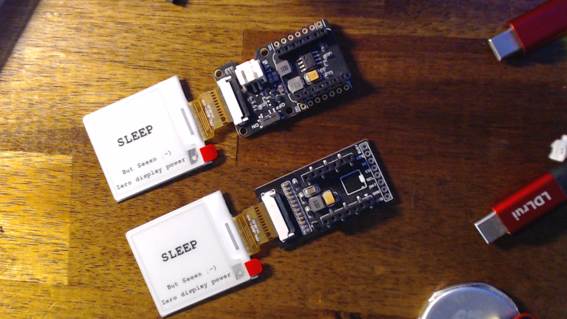
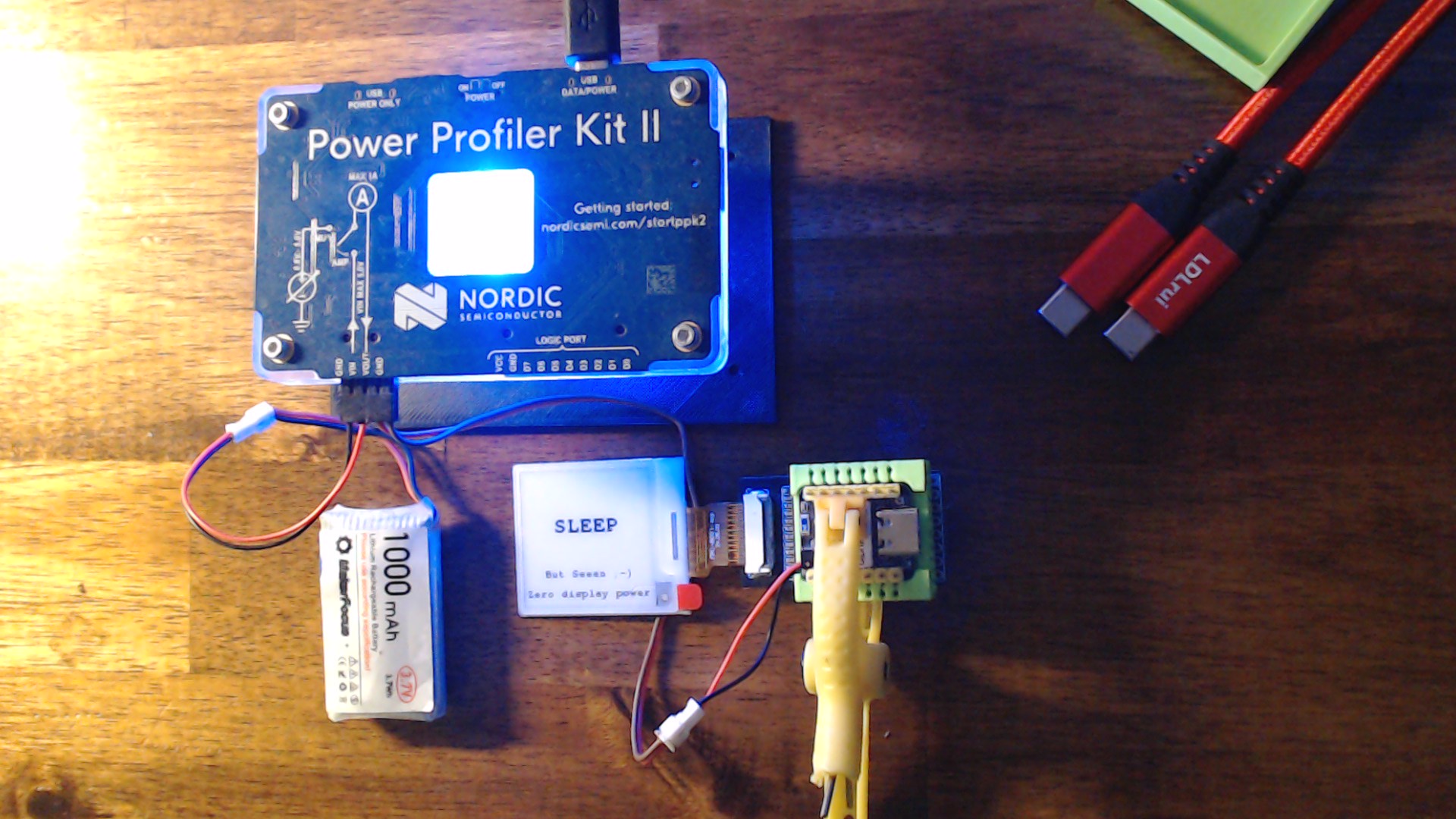
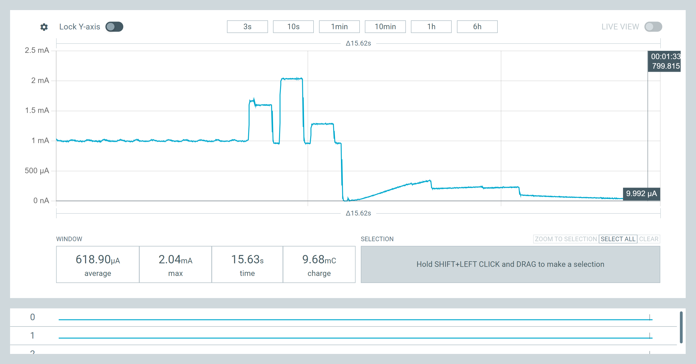
and here is a bad Flash shutdown fail or missed command, You can see the end that consumption go’s ma. high. TEST everything.. 
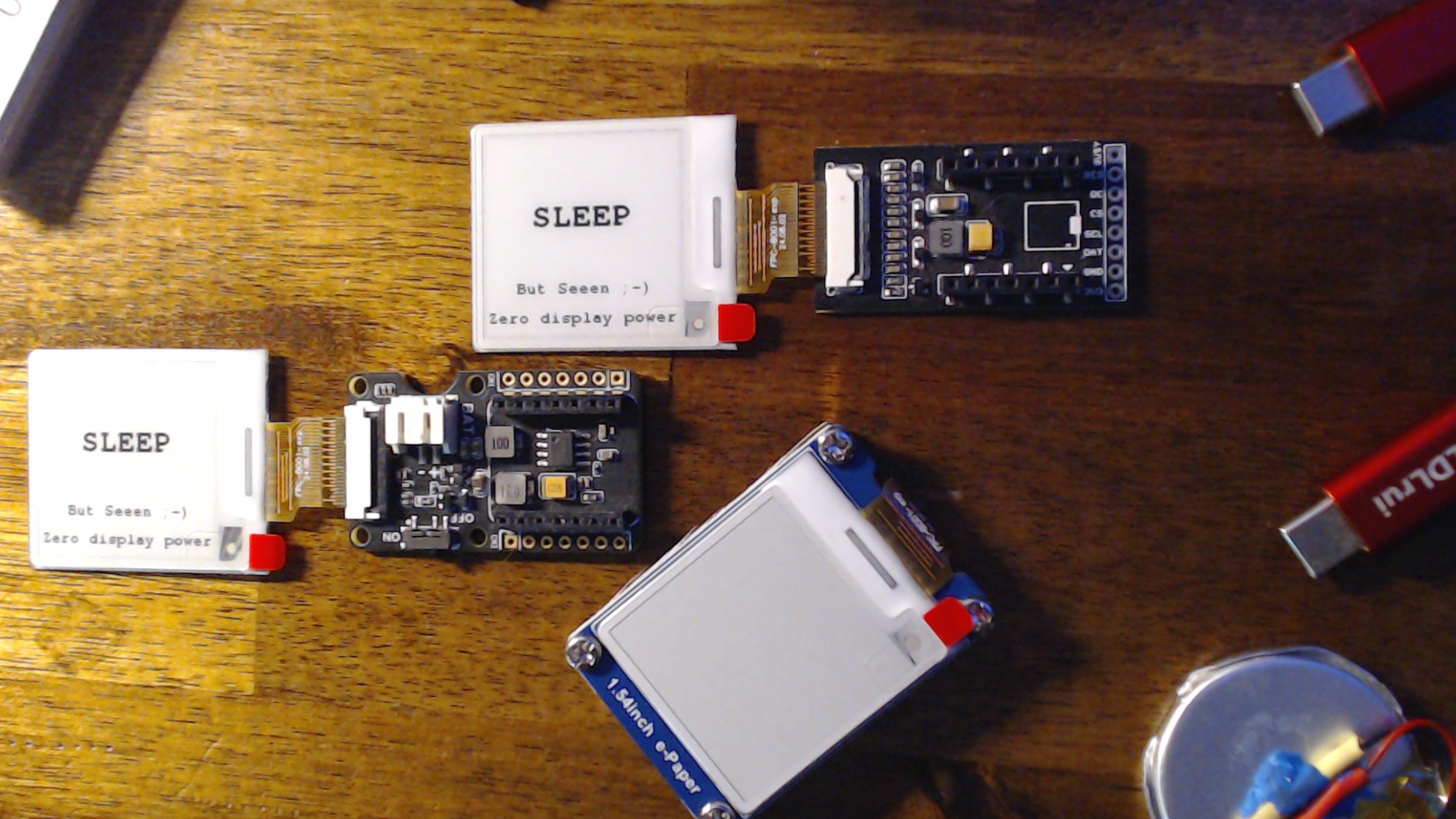
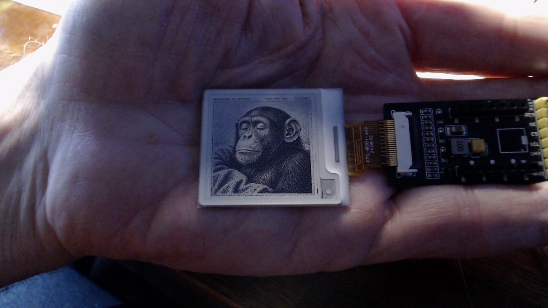
 (it’s not much bigger than a stamp), now that’s a refrigerator magnet.


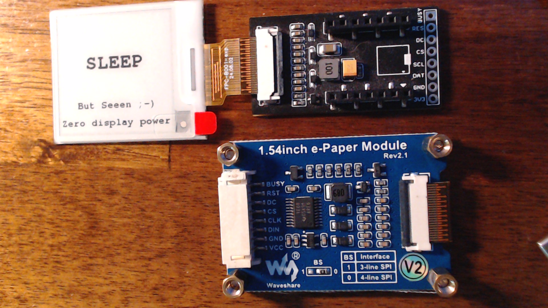
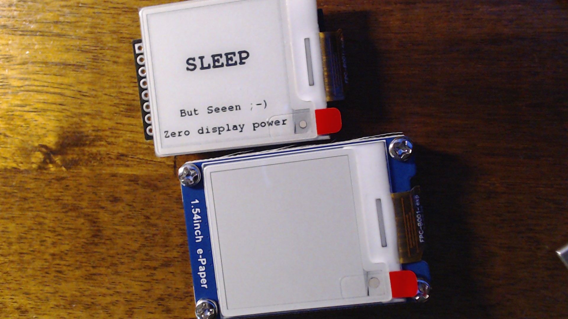
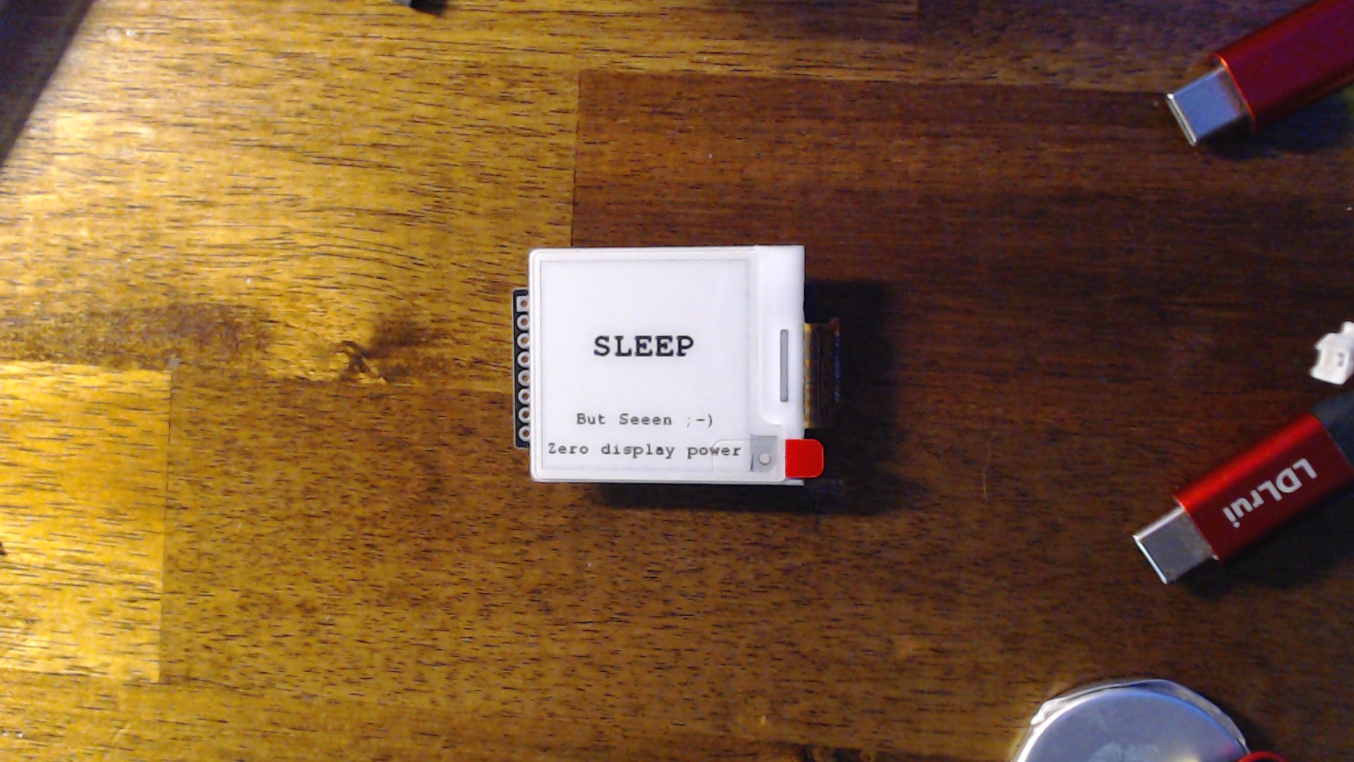
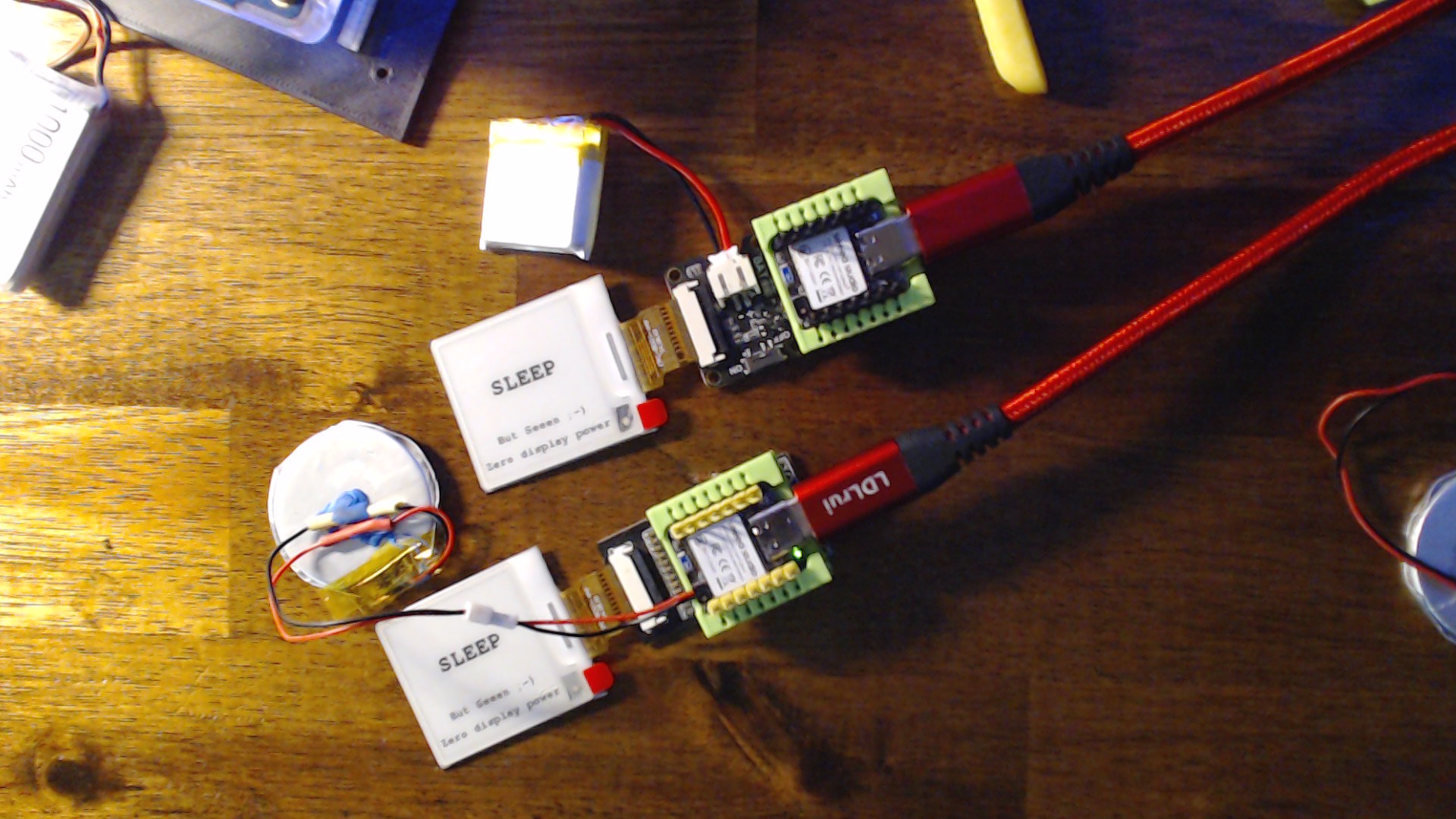

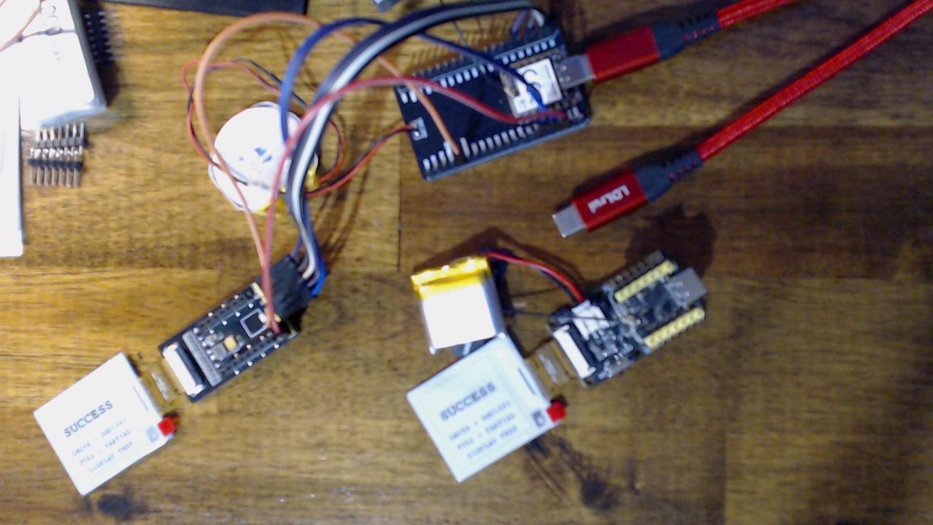

 the Truth (by shortening or bypassing) the Panel manufacture proper performance guideline to extend the life or performance marketing info of the panel.
 could verify these numbers.
 are having with this area of tech.
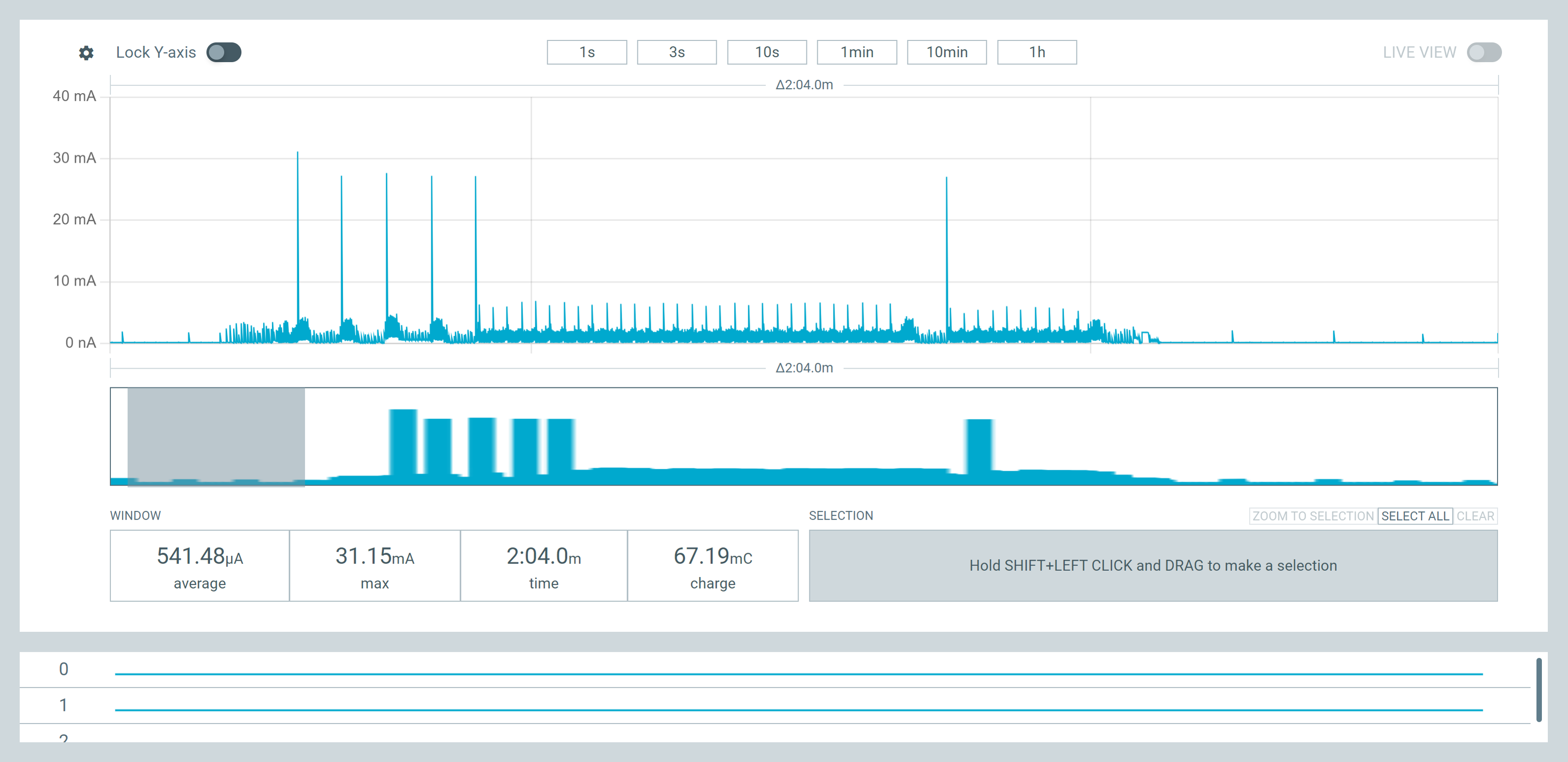


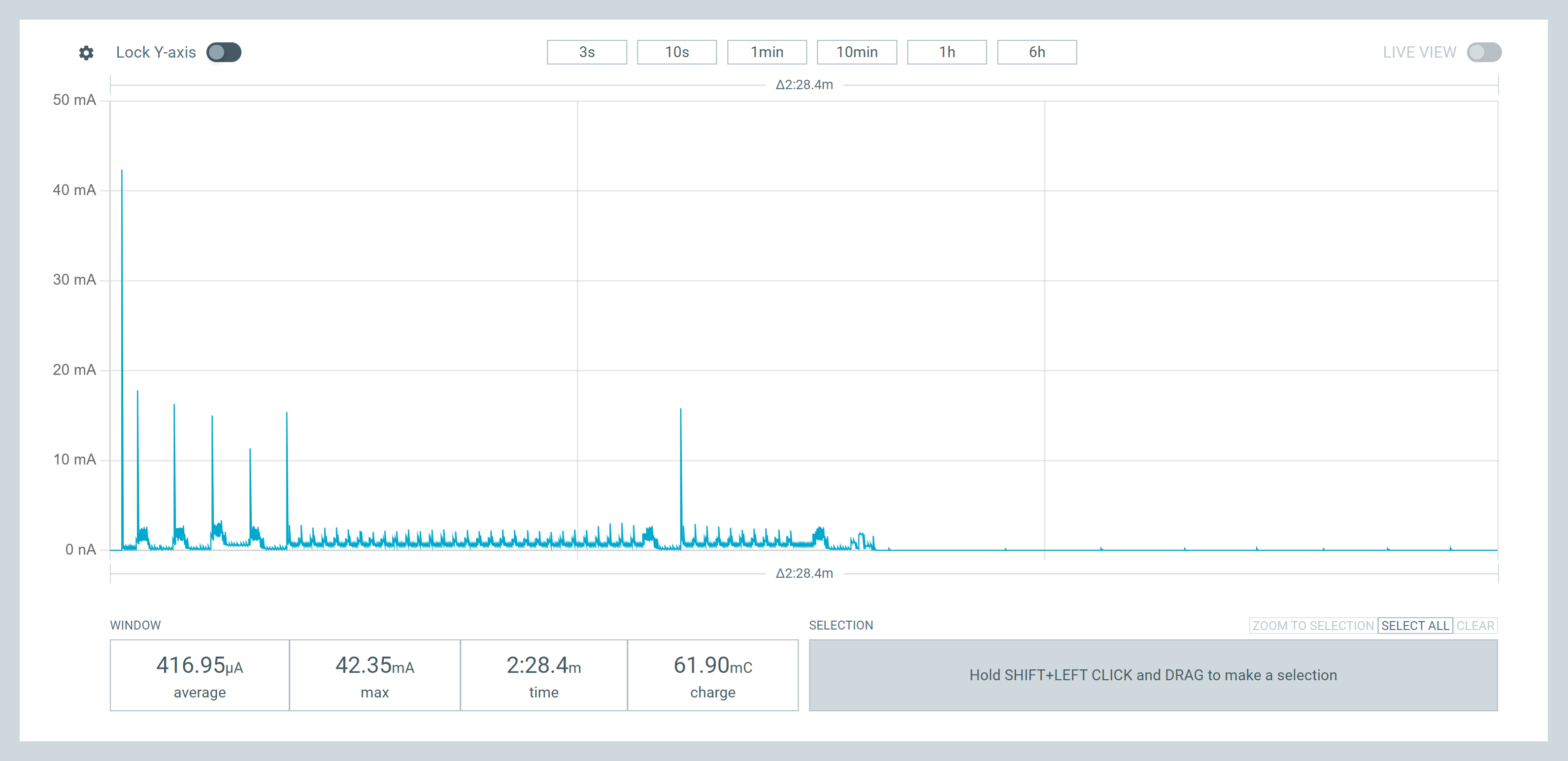

 PJ
PJ 
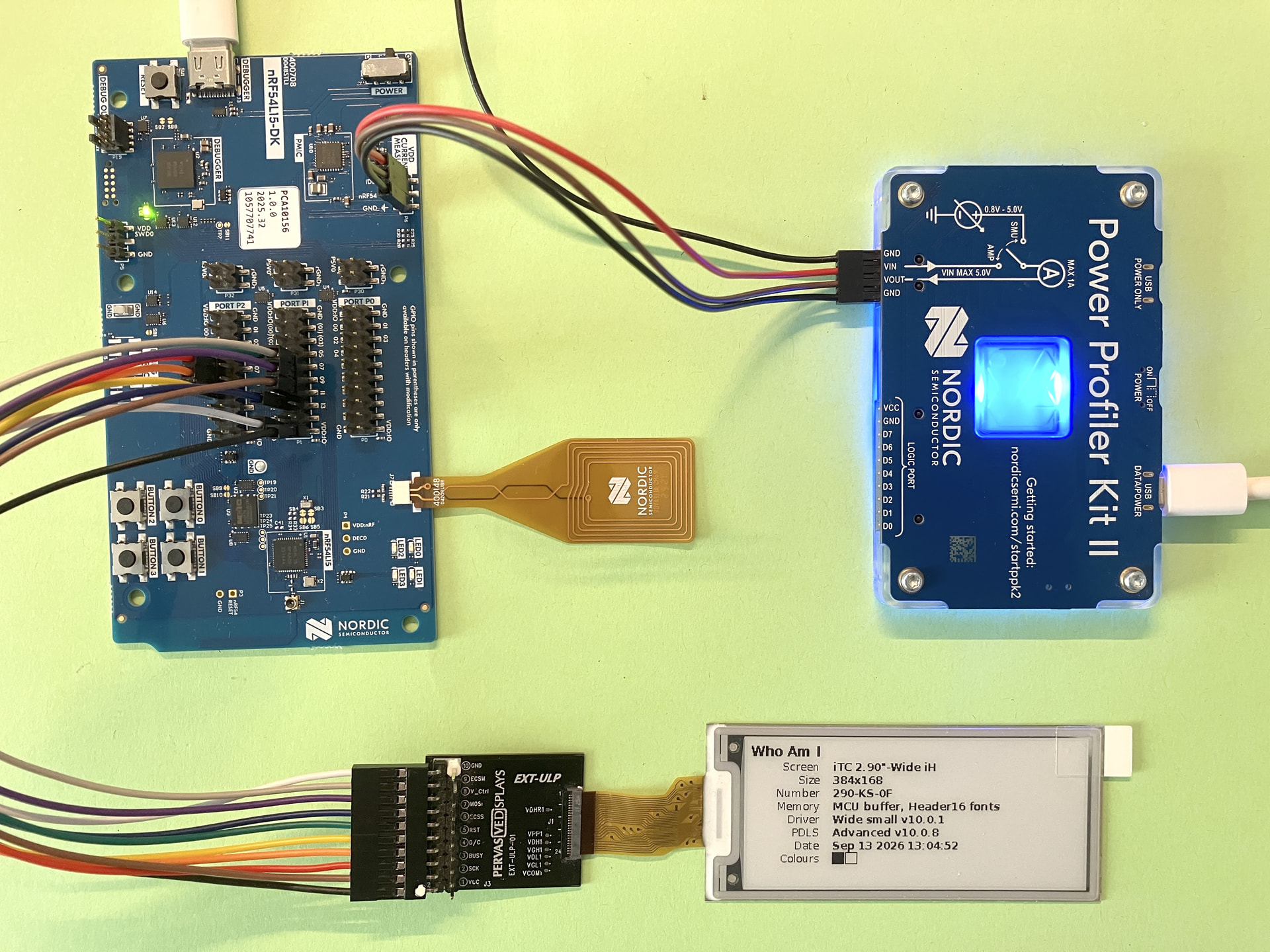
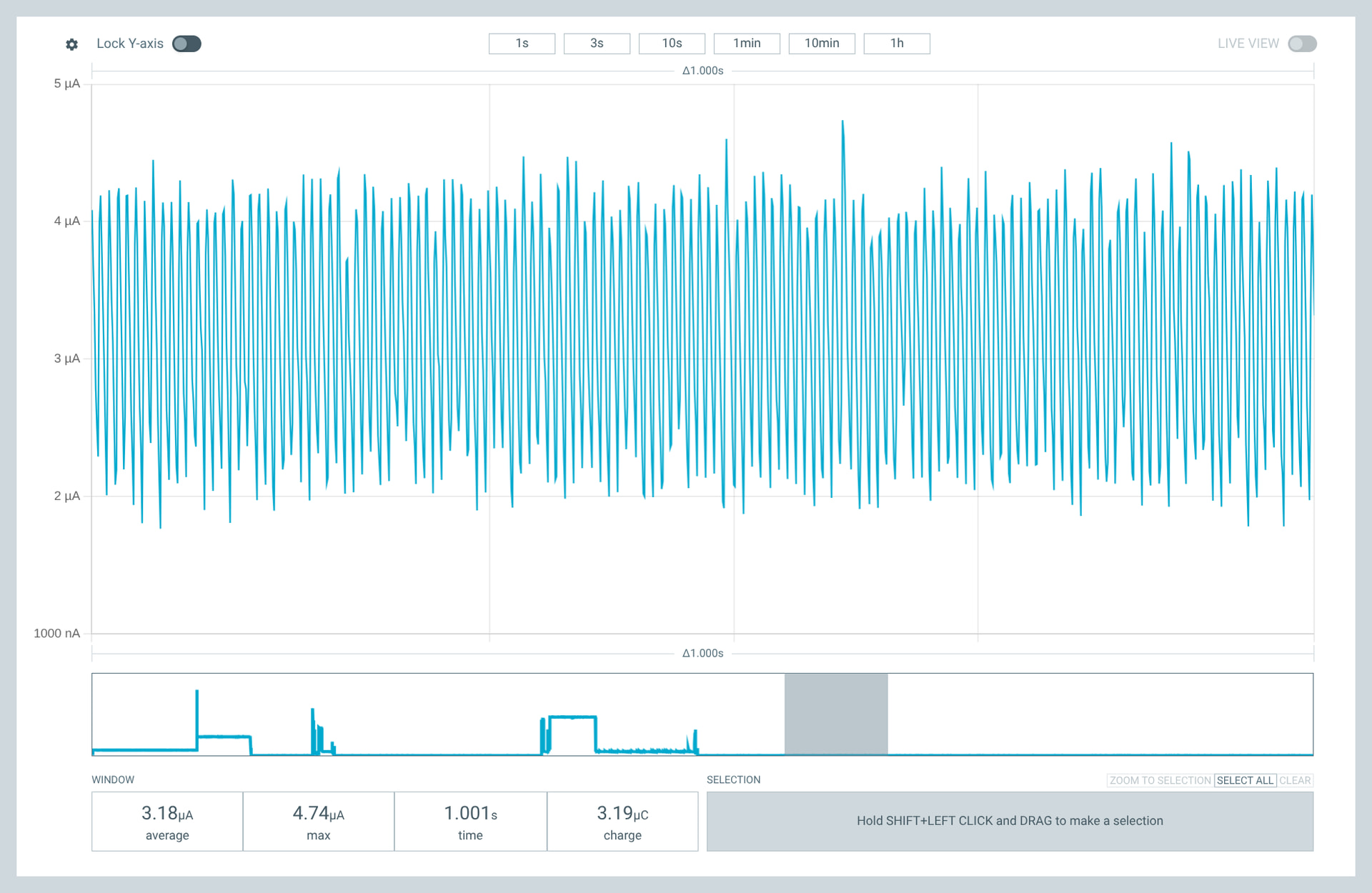


 the Xiao will go that low (some DK’s have no Flash) but You get the nRF54LM20A and no problem plus “SHIP MODE” among other enhancements besides the PMIC, true Battery SOC info i2c , that is the Bomb.