I’m trying to port Circuitpython to Wio Rp2040 and I’m having trouble understanding how ESP8285 is connected to RP2040. The information in the schematic is confusing and from what I could observe, some other users are also having the same issues. Porting Circuitpython to the board should be relatively straightforward. From what I could understand, the ESP8285 is connected via SPI (which one? which pins) and receives AT commands from the RP2040. It seems to me that the adafruit_esp32spi library could be configured to resolve the wifi connection. Do you intend to make this port? Or could you detail the connections better so that we users could find out?
Taking some notes in order to port Circuitpython to Wio RP2040
Trying to figure out which interface is connected to ESP8285 - appears to be SPI1
On ESP8285 Datasheet
ESP8285 features 17 GPIOs, all of which can be assigned to support various functions of LED lights and buttons. Definitions of some GPIOs that are assigned with certain functions
in demo application design are shown as below.
Pin Name Pin Num IO Function Name
MTCK 12 IO13 Button (Reset)
GPIO0 15 IO0 Wi-Fi Light
MTDI 10 IO12 Link Light
Altogether three interfaces have been defined, one is for the button (INPUT), while the other two are for LED light (OUTPUTS). Generally, MTCK is used to control the reset button, GPIO0 is used as a signal to indicate the Wi-Fi working state, MTDI is used as a signal light to indicate communication status between the device and the server.
Other Special Pins on ESP8285
EXT_RSTB INPUT External reset signal (ACTIVE LOW)
XPD_DCDC I/O Deep-sleep wakeup (need to be connected to EXT_RSTB); GPIO16.
CHIP_PU I Chip Enable
		`High: On, chip works properly`

		`Low: Off, small current consumed`
From Adafruit_CircuitPython_ESP32SPI library, I need three pins…
esp32_cs = DigitalInOut(board.ESP_CS) // Probably SPI_CS - RP2040 pin GP9
esp32_ready = DigitalInOut(board.ESP_BUSY) // Defined as INPUT. Maybe related to pin 21? ACTIVE LOW. Could be ESP8285 GPIO0?
esp32_reset = DigitalInOut(board.ESP_RESET) // Defined as OUTPUT. Could be connected to ESP8285 MTCK pin?
User in forum informs that Micropython port for this board is same as this version:
So, i want to check if there is any indication of connections in code…
in this Micropython port, this pins are described: (file machine_spi.c)
#define DEFAULT_SPI_BAUDRATE (200000)
#define DEFAULT_SPI_POLARITY (0)
#define DEFAULT_SPI_PHASE (0)
#define DEFAULT_SPI_BITS (8)
#define DEFAULT_SPI_FIRSTBIT (SPI_MSB_FIRST)
#define DEFAULT_SPI0_SCK (2) // SPI0 SCK
#define DEFAULT_SPI0_MOSI (3) // SPI0 TX MOSI
#define DEFAULT_SPI0_MISO (4) // SPI0 RX MISO
// Probably ESP8285 is connected to SPI1...
#define DEFAULT_SPI1_SCK (10) // SPI1 SCK
#define DEFAULT_SPI1_MOSI (11) // SPI1 TX MOSI
#define DEFAULT_SPI1_MISO (8) // SPI1 RX MISO
#define SPI_CS 9 // SPI1 CSn - Active LOW
#define SPI_HANDSHARK 21 // Handshake? ESP32_Ready?
RP2040 Gpio0 is reset
In GitHub - is-qian/rp2040-spi file mod_wifi_spi.c
//esp8285 power on
mp_hal_pin_output(21); // SPI0 CSn - SPI_HANDSHARK? > esp32_ready?
mp_hal_pin_output(22); // SPI0 SCK
mp_hal_pin_output(24); // SPI1 RX - On pico, this is not exposed in pinout...
mp_hal_pin_output(25); // SPI1 CSn - Onboard LED on Raspberry Pi pico Board
mp_hal_pin_output(SPI_CS); // Pin 9
gpio_put(21,1); // On power ON, activate this pins (HIGH)
gpio_put(22,1); // Which one is connected to ESP8285 CHIP_PU Pin?
gpio_put(24,1);
gpio_put(SPI_CS,0); // Active LOW
gpio_put(25,0); // On Power ON, LOW
mp_hal_pin_input(SPI_HANDSHARK); // This pin is checked in order to see if 8285 is ready LOW if ready
gpio_put(SPI_CS,1); // Disable SPI and wait
// esp8285 power down
mp_hal_pin_output(21); // SPI0 CSn - SPI_HANDSHARK? > esp32_ready?
mp_hal_pin_output(22); // SPI0 SCK
mp_hal_pin_output(24); // SPI1 RX - On pico, this is not exposed in pinout...
mp_hal_pin_output(25); // SPI1 CSn - Onboard LED on Raspberry Pi pico Board
gpio_put(21,0); // On power OFF, deactivate this pins (LOW)
gpio_put(22,0); // Which one is connected to ESP8285 CHIP_PU Pin?
gpio_put(24,0); // This two GPIOs maybe is custom used on this board...
gpio_put(25,1); // On power OFF, HIGH
Your solution looks a lot like the Challenger RP2040 Wifi, which already has a port for Circuitpython. Challenger RP2040 WiFi Download
Has any progress been made on understanding how the WIO’s RP2040 is connected to the ESP8285?
the Challenger RP2040 uses UART to send ‘AT’ commands to the 8285, but looks like the Wio uses SPI?
continuing to document my findings, in case this helps someone else:
I created a circuitpython branch (soon to be a pull request) for the wio2040 port:
included in the commit is a schematic received from seeed with the connections between the 2040 and the 8285, most notably the spi connection between signals:
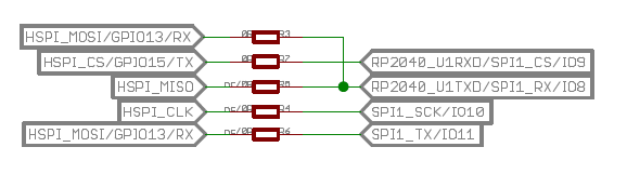
(8285 signals on left, 2040 signals on the right)
also, as mentioned in previous posts, this confirms a few things:
RSTis GPIO22 (connected to 8285 reset)WAKEUPis GPIO23 (connected to the XPD_DCDC on the 8285 for deep-sleep wakeup)ENABLEis GPIO24 (connected to 8285 enable)POWERis GPIO25 (enables/disables power to the entire 8285, presumably because even whenENABLEis low, the 8285 draws power)
more notes:
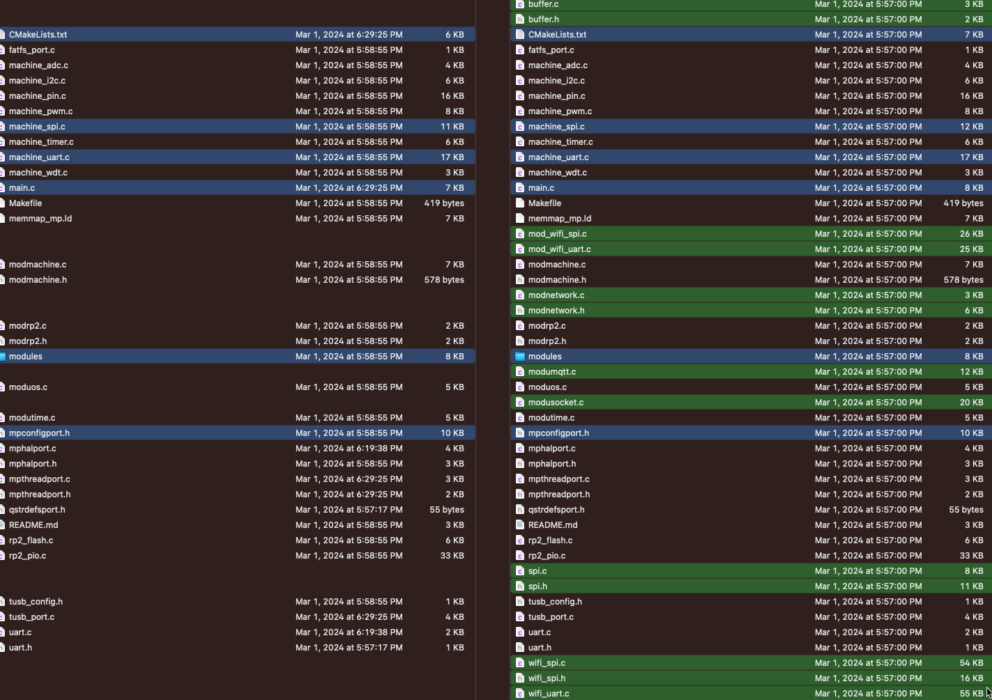
Seeed’s micropython for the wio wasn’t forked, but copied, so upgrading from the currently supported version of v1.15 to currently stable v1.22 is a challenge. But it looks like it was copied (give or take) around May 14, 2021 (commit 47e6c52f) which helped to differentiate the files that were modified to support the wio vs. the files modified since then:
I’ve compiled your firmware version, but it still lacks Wifi support. I’m trying a second build, this time changing a few lines of the mpconfigboard.mk file to add wifi support and some frozen modules.
In file mpconfigboard.mk
CIRCUITPY_WIFI = 1

FROZEN_MPY_DIRS += $(TOP)/frozen/Adafruit_CircuitPython_ESP32SPI
FROZEN_MPY_DIRS += $(TOP)/frozen/Adafruit_CircuitPython_Requests
FROZEN_MPY_DIRS += $(TOP)/frozen/Adafruit_CircuitPython_BusDevice
This line CIRCUITPY_WIFI = 1 generates a lot of errors. I think that is related to Pico W wifi only. Trying to compile without it…
Not working, yet.
import board
import busio
from digitalio import DigitalInOut

from adafruit_esp32spi import adafruit_esp32spi
import adafruit_requests as requests

print("ESP32 SPI hardware test")

esp32_cs = DigitalInOut(board.ESP_CS)
esp32_ready = DigitalInOut(board.ESP_HANDSHAKE)
esp32_reset = DigitalInOut(board.ESP_RESET)

spi = busio.SPI(board.ESP_CLK, board.ESP_MOSI, board.ESP_MISO)
esp = adafruit_esp32spi.ESP_SPIcontrol(spi, esp32_cs, esp32_ready, esp32_reset)

if esp.status == adafruit_esp32spi.WL_IDLE_STATUS:
    print("ESP32 found and in idle mode")
print("Firmware vers.", esp.firmware_version)
print("MAC addr:", [hex(i) for i in esp.MAC_address])

for ap in esp.scan_networks():
    print("\t%s\t\tRSSI: %d" % (str(ap['ssid'], 'utf-8'), ap['rssi']))

print("Done!")
Giving this error:
Traceback (a última chamada mais recente):
Arquivo “”, linha 17, em
Arquivo “adafruit_esp32spi/adafruit_esp32spi.py”, linha 351, em status
Arquivo “adafruit_esp32spi/adafruit_esp32spi.py”, linha 340, em _send_command_get_response
Arquivo “adafruit_esp32spi/adafruit_esp32spi.py”, linha 254, em _send_command
TimeoutError: ESP32 timed out on SPI select