SPI on XIAO esp32s3

Hi,
I try to use spi on xiao esp32s3. Whatever I do, I can not send/receive data. I tried SPI2_HOST and SPI3_HOST. When I set flag HALF-DUPLEX (which I need) gives me errors, … Has someone got working example code on Espressif?
Do I have to change setup something on esp-idf to make it work?

spi_bus_config_t Config;
Config.mosi_io_num = 9;
Config.miso_io_num = 8;
Config.sclk_io_num = 7;
Config.max_transfer_sz = 0;
Config.quadwp_io_num = -1; // -1 not used
Config.quadhd_io_num = -1; // -1 not used
Config.intr_flags = 0;
Config.data0_io_num = -1;
Config.data1_io_num = -1;
Config.data2_io_num = -1;
Config.data3_io_num = -1;
Config.data4_io_num = -1;
Config.data5_io_num = -1;
Config.data6_io_num = -1;
Config.data7_io_num = -1;
Config.flags = 0;//SPICOMMON_BUSFLAG_GPIO_PINS | SPICOMMON_BUSFLAG_MASTER | SPICOMMON_BUSFLAG_MISO | SPICOMMON_BUSFLAG_MOSI | SPICOMMON_BUSFLAG_SCLK;
//Config.flags = 0 ;
Config.isr_cpu_id = INTR_CPU_ID_0;
spi_bus_initialize(SPI2_HOST, &Config, SPI_DMA_CH_AUTO);//SPI_DMA_CH_AUTO);

printf("-----1-----");

spi_device_interface_config_t ConfigInterface;
ConfigInterface.command_bits = 0;
ConfigInterface.address_bits = 0;
ConfigInterface.dummy_bits = 0;
ConfigInterface.mode = 0;
ConfigInterface.duty_cycle_pos = 128; // default 128 = 50%/50% duty
ConfigInterface.cs_ena_pretrans = 0; // 0 not used
ConfigInterface.cs_ena_posttrans = 0; // 0 not used
ConfigInterface.clock_speed_hz = SPI_MASTER_FREQ_10M;
ConfigInterface.spics_io_num = 44;
ConfigInterface.flags = 0;//| SPI_DEVICE_NO_DUMMY; //| SPI_DEVICE_HALFDUPLEX;
ConfigInterface.queue_size = 8;
ConfigInterface.pre_cb = NULL;
ConfigInterface.post_cb = NULL;
ConfigInterface.input_delay_ns = 50;
spi_bus_add_device(SPI2_HOST, &ConfigInterface, &SPIHandle);

it may be that the physical pin numbers and the chip numbers change and your code may not be
have you tried with another XIAO C3 perhaps?

Sorry i only know how to use Arduino IDE (unfortunatly)
below is the config file for XIAO ESP32S3

#ifndef Pins_Arduino_h
#define Pins_Arduino_h

#include <stdint.h>
#include “soc/soc_caps.h”

#define USB_VID 0x2886
#define USB_PID 0x0056

#define EXTERNAL_NUM_INTERRUPTS 49
#define NUM_DIGITAL_PINS 49
#define NUM_ANALOG_INPUTS 20

static const uint8_t LED_BUILTIN = 21;
#define BUILTIN_LED LED_BUILTIN // backward compatibility
#define LED_BUILTIN LED_BUILTIN

#define analogInputToDigitalPin(p) (((p)<NUM_ANALOG_INPUTS)?(analogChannelToDigitalPin(p)):-1)
#define digitalPinToInterrupt(p) (((p)<NUM_DIGITAL_PINS)?(p):-1)
#define digitalPinHasPWM(p) (p < EXTERNAL_NUM_INTERRUPTS)

static const uint8_t TX = 43;
static const uint8_t RX = 44;

static const uint8_t SDA = 5;
static const uint8_t SCL = 6;

static const uint8_t SS = 44;
static const uint8_t MOSI = 9;
static const uint8_t MISO = 8;
static const uint8_t SCK = 7;

static const uint8_t A0 = 1;
static const uint8_t A1 = 2;
static const uint8_t A2 = 3;
static const uint8_t A3 = 4;
static const uint8_t A4 = 5;
static const uint8_t A5 = 6;
static const uint8_t A8 = 7;
static const uint8_t A9 = 8;
static const uint8_t A10 = 9;

static const uint8_t D0 = 1;
static const uint8_t D1 = 2;
static const uint8_t D2 = 3;
static const uint8_t D3 = 4;
static const uint8_t D4 = 5;
static const uint8_t D5 = 6;
static const uint8_t D6 = 43;
static const uint8_t D7 = 44;
static const uint8_t D8 = 7;
static const uint8_t D9 = 8;
static const uint8_t D10 = 9;

static const uint8_t T1 = 1;
static const uint8_t T2 = 2;
static const uint8_t T3 = 3;
static const uint8_t T4 = 4;
static const uint8_t T5 = 5;
static const uint8_t T6 = 6;
static const uint8_t T7 = 7;
static const uint8_t T8 = 8;
static const uint8_t T9 = 9;

#endif /* Pins_Arduino_h */

FYI according to arduino sketch

Hi there,
I do!
So on the ESP32S3 the SPI is different, than the C3 for example.
Have a Look the Demo code on The Xiao Grove Expansion Board with add-on Flash chip.
The chip supports differently the SPI busses, Also QSPI or Some modes are reserved for on board.
As long as you define the custom pins in the sketch NO NEED to modify the pins file. :face_with_peeking_eye: (they all support pin multiplexing) That should NEVER be except last resort.

Are you trying to use a Flash device or an ordinary SPI device?
can you post the code using the Code Quotes… We can see what is the issue.
HTH
GL :slight_smile: PJ

What is the hardware connections you have?

I have installed arduino but it also does not work correctly

Hi,
It is connected to our custom board, which is work fine on Sierrawireless unit FX30. I wanted to use other chip, so I tried xiao ESP32s3. Code below should work but it does not return correct data.

gpio_reset_pin(GPIO_NUM_44);
gpio_set_direction(GPIO_NUM_44, GPIO_MODE_OUTPUT);
spi_bus_config_t Config;
Config.mosi_io_num = GPIO_NUM_9;
Config.miso_io_num = GPIO_NUM_8;
Config.sclk_io_num = GPIO_NUM_7;
Config.max_transfer_sz = 0;
Config.quadwp_io_num = -1;  // -1 not used
Config.quadhd_io_num = -1;  // -1 not used
Config.intr_flags = 0;
Config.data0_io_num = -1;
Config.data1_io_num = -1;
Config.data2_io_num = -1;
Config.data3_io_num = -1;
Config.data4_io_num = -1;
Config.data5_io_num = -1;
Config.data6_io_num = -1;
Config.data7_io_num = -1;
//When I set flags Config.flags = SPICOMMON_BUSFLAG_MASTER| SPICOMMON_BUSFLAG_MISO | SPICOMMON_BUSFLAG_MOSI | SPICOMMON_BUSFLAG_SCLK I have got w error
//E (372) spi: mosi pin required.
//E (382) spi: miso pin required.
//E (382) spi: spicommon_bus_initialize_io(598): not all required capabilities satisfied.
Config.flags = 0;//SPICOMMON_BUSFLAG_MASTER| SPICOMMON_BUSFLAG_MISO | SPICOMMON_BUSFLAG_MOSI | SPICOMMON_BUSFLAG_SCLK;
Config.isr_cpu_id = INTR_CPU_ID_0;
if(ESP_OK == spi_bus_initialize(SPI3_HOST, &Config, SPI_DMA_CH_AUTO))
{
    printf("-----OK-----");
}

spi_device_interface_config_t ConfigInterface;
ConfigInterface.command_bits = 0;
ConfigInterface.address_bits = 0;
ConfigInterface.dummy_bits = 0;
ConfigInterface.mode = 0;
ConfigInterface.duty_cycle_pos = 128;  // default 128 = 50%/50% duty
ConfigInterface.cs_ena_pretrans = 0;  // 0 not used
ConfigInterface.cs_ena_posttrans = 0;  // 0 not used
ConfigInterface.clock_speed_hz = 400000;
ConfigInterface.spics_io_num = GPIO_NUM_44;
//SPI_DEVICE_HALFDUPLEX does not work
ConfigInterface.flags = 0;//SPI_DEVICE_HALFDUPLEX;//| SPI_DEVICE_NO_DUMMY; //| SPI_DEVICE_HALFDUPLEX;
ConfigInterface.queue_size = 8;
ConfigInterface.pre_cb = NULL;
ConfigInterface.post_cb = NULL;
ConfigInterface.input_delay_ns = 0;
if(ESP_OK == spi_bus_add_device(SPI3_HOST, &ConfigInterface, &SPIHandle))
{
    printf("-----OK-----");
}

uint8_t WriteDataPtr[] = {0x08, 0xE7};
uint8_t ReadDataPtr[2];

spi_transaction_t transaction;
    transaction.flags = 0;
    transaction.cmd = 0;
    transaction.addr = 0;
    transaction.length = 16;
    transaction.rxlength = 0;
    transaction.tx_buffer = WriteDataPtr;
    transaction.rx_buffer = ReadDataPtr;
    esp_err_t err =spi_device_transmit(SPIHandle, &transaction);
    if(err == ESP_OK)
    {
        //ReadDataPtr[0], ReadDataPtr[1] returns constant numbers
        printf("SPI Read OK\n");
        return true;
    }
    else
    {
        return false;
    }

Hit there,
Try
8,9,10… On Xiao.

  pinMode(D6, INPUT_PULLUP);  // /WP
  pinMode(D7, INPUT_PULLUP);  // /HOLD
  pinMode(SS_SPI0, OUTPUT);          // CS for flash
  digitalWrite(SS_SPI0, HIGH);       // <-- Set CS pin HIGH to deselect
Serial.println("--------------"); Check what it thinks they are.
  Serial.println(SS_SPI0);
  Serial.println(MOSI); // master out, slave in
  Serial.println(MISO); // master in, slave out
  Serial.println(SCK);  // clock
 Serial.println("--------------");

HTH
GL :slight_smile: PJ

Hi,
I have got correct settings

image

I would say NO , they are not correct. for the Xiao ESP32S3

Change them to , Sclk 8, MISO 9 and MOSI 10 leave the SS/CS
if that doesn’t work use the physical pin number of the chips pin.
I.e. 9, 10, 11…
LMK
HTH
GL :slight_smile: PJ

Hi,
It does not work. I wrote to tech support. I have received following response:
Please check the following precautions when you use the spi pins of XIAO ESP32S3:
Pin Multiplexing | Seeed Studio Wiki
You need to cut the pcba as labeled in figure 1, it’s connections are located inside the pcb.
I did not want to cut anything so I bought eval kit based on ESP32-WROOM-32. The new eval kit communicate with my board via SPI, but I have got wrong data. It does not work correctly. ESP32 is nightmare ( even codes from EDP-IDF do not work). I have to come back to Sierrawireless chips. Sierra processors are not cheap, but works.

Thanks for your help.

Hi there, Sure No Problem
It should work, Can you post the code I can Try it and Verify for you.

Those pin assignments are incorrect for Xiao (7,8,9,) should be (8,9,10)
Period.
HTH
GL :slight_smile: PJ

Hi there,
So this is Running on the C3 and should also run on the S3
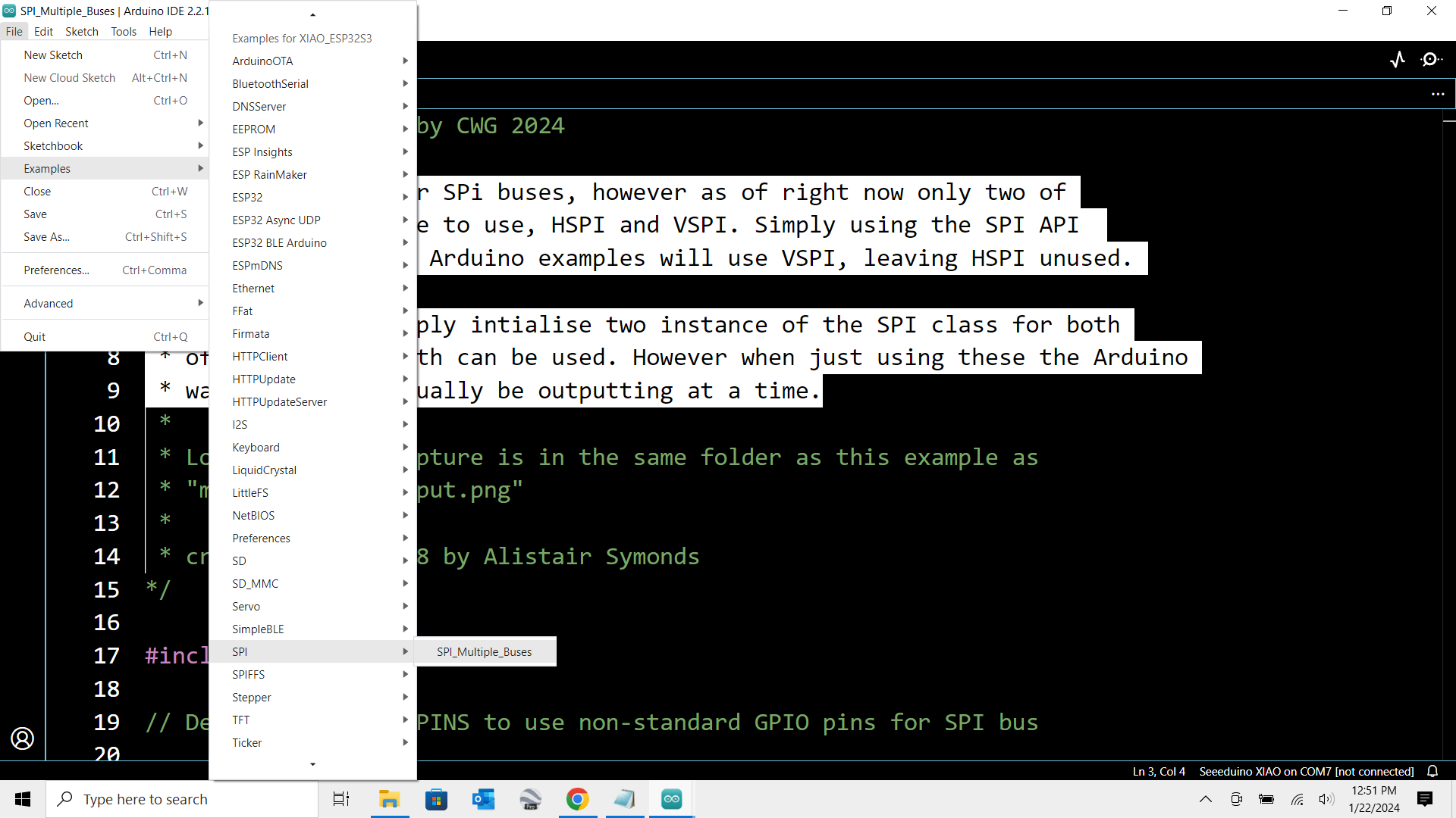
Try it and report back, It’s the Busses sketch modified, There’s lots of good info in there, so look it over.


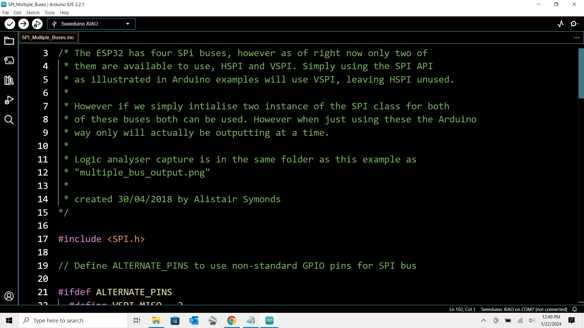
/* The ESP32 has four SPi buses, however as of right now only two of
 * them are available to use, HSPI and VSPI. Simply using the SPI API 
 * as illustrated in Arduino examples will use VSPI, leaving HSPI unused.
 * 
 * However if we simply intialise two instance of the SPI class for both
 * of these buses both can be used. However when just using these the Arduino
 * way only will actually be outputting at a time.
 * 
 * Logic analyser capture is in the same folder as this example as
 * "multiple_bus_output.png"
 * 
 * created 30/04/2018 by Alistair Symonds
 */
//#include <SPI.h>
#include <SPIMemory.h>
uint8_t pageBuffer[256];
String serialCommand;
char printBuffer[128];
uint32_t addr;
uint8_t dataByte;
uint16_t dataInt;
String inputString, outputString;
// Define ALTERNATE_PINS to use non-standard GPIO pins for SPI bus
//#define ALTERNATE_PINS
#ifdef ALTERNATE_PINS
  #define VSPI_MISO   2
  #define VSPI_MOSI   4
  #define VSPI_SCLK   0
  #define VSPI_SS     33

  #define HSPI_MISO   26
  #define HSPI_MOSI   27
  #define HSPI_SCLK   25
  #define HSPI_SS     32
#else
  #define VSPI_MISO   MISO
  #define VSPI_MOSI   MOSI
  #define VSPI_SCLK   SCK
  #define VSPI_SS     SS
  
  #define HSPI_MISO   12
  #define HSPI_MOSI   13
  #define HSPI_SCLK   14
  #define HSPI_SS     15
#endif

#if CONFIG_IDF_TARGET_ESP32S2 || CONFIG_IDF_TARGET_ESP32S3
#define VSPI FSPI
#endif
#define VSPI FSPI
static const int spiClk = 1000000; // 1 MHz

//uninitalised pointers to SPI objects
SPIClass * fspi = NULL;
SPIClass * hspi = NULL;
#define SS 3
//SPIFlash flash;
SPIFlash flash(SS, &SPI);       //Use this constructor if using an SPI bus other than the default SPI. Only works with chips with more than one hardware SPI bus
void setup() {
 Serial.begin(9600);
  while (!Serial) delay(2100);
  
  Serial.println();
  Serial.println(" Program " __FILE__ " compiled on " __DATE__ " at " __TIME__ );
  Serial.println("----RESET----");
   Serial.print(F("Initialising"));
  for (uint8_t i = 0; i < 10; ++i)
  {
    Serial.print(F("."));
  }
  Serial.println();

  //initialise two instances of the SPIClass attached to VSPI and HSPI respectively
  fspi = new SPIClass(FSPI);
  hspi = new SPIClass(HSPI);
  
  //clock miso mosi ss

#ifndef ALTERNATE_PINS
  //initialise vspi with default pins
  //SCLK = 18, MISO = 19, MOSI = 23, SS = 5
  fspi->begin();
#else
  //alternatively route through GPIO pins of your choice
  fspi->begin(VSPI_SCLK, VSPI_MISO, VSPI_MOSI, VSPI_SS); //SCLK, MISO, MOSI, SS
#endif

#ifndef ALTERNATE_PINS
  //initialise hspi with default pins
  //SCLK = 14, MISO = 12, MOSI = 13, SS = 15
  hspi->begin();
#else
  //alternatively route through GPIO pins
  hspi->begin(HSPI_SCLK, HSPI_MISO, HSPI_MOSI, HSPI_SS); //SCLK, MISO, MOSI, SS
#endif

  //set up slave select pins as outputs as the Arduino API
  //doesn't handle automatically pulling SS low
  pinMode(fspi->pinSS(), OUTPUT); //VSPI SS
  pinMode(hspi->pinSS(), OUTPUT); //HSPI SS
 digitalWrite(SS, LOW);       // <-- Set CS pin HIGH to deselect
  
Serial.println (VSPI_SS);
Serial.println (VSPI_MOSI);
Serial.println (VSPI_MISO);
Serial.println (VSPI_SCLK);

Serial.println();

Serial.println (HSPI_SS);
Serial.println (HSPI_MOSI);
Serial.println (HSPI_MISO);
Serial.println (HSPI_SCLK);
pinMode(SS, OUTPUT);
Serial.println();
digitalWrite(SS, LOW);       // <-- Set CS pin HIGH to deselect
Serial.print("MOSI:");
  Serial.println(MOSI);
  Serial.print("MISO: ");
  Serial.println(MISO);
  Serial.print("SCK:  ");
  Serial.println(SCK);
  Serial.print("SS:   ");
  Serial.println(SS);
//digitalWrite(VSPI_SS,LOW);
flash.begin();
//Serial.print(F("Flash size: "));
 // Serial.print((long)(flash.getCapacity()/1000));
 // Serial.println(F("Kb"));
  //digitalWrite(spi->pinSS(), HIGH); //pull ss high to signify end of data transfer
  //spi->endTransaction();
//digitalWrite(SS, HIGH);       // <-- Set CS pin HIGH to deselect
//digitalWrite(VSPI_SS,HIGH);
//flash.setClock(12000000); // uncomment here for Arduino SAMD boards
printLine();
      
      printLine();
      uint8_t b1, b2, b3;
      uint32_t JEDEC = flash.getJEDECID();
      //uint16_t ManID = flash.getManID();
      b1 = (JEDEC >> 16);
      b2 = (JEDEC >> 8);
      b3 = (JEDEC >> 0);
      clearprintBuffer();
      sprintf(printBuffer, "Manufacturer ID: %02xh\nMemory Type: %02xh\nCapacity: %02xh", b1, b2, b3);
      Serial.println(printBuffer);
      clearprintBuffer();
      sprintf(printBuffer, "JEDEC ID: %04xh", JEDEC);
      Serial.println(printBuffer);
      printLine();
      //printNextCMD();

}

// the loop function runs over and over again until power down or reset
void loop() {
  //use the SPI buses
  //spiCommand(fspi, 0b01010101); // junk data to illustrate usage
  //spiCommand(hspi, 0b11001100);
  delay(1000);
}

void spiCommand(SPIClass *spi, byte data) {
  //use it as you would the regular arduino SPI API
  spi->beginTransaction(SPISettings(spiClk, MSBFIRST, SPI_MODE0));
  digitalWrite(spi->pinSS(), LOW); //pull SS slow to prep other end for transfer
  spi->transfer(data);
  digitalWrite(spi->pinSS(), HIGH); //pull ss high to signify end of data transfer
  spi->endTransaction();
}

void printLine()
{
  Serial.println(F("----------------------------------------------------------------------------------------------------------------------------------"));
}

void clearprintBuffer()
{
  for (uint8_t i = 0; i < 128; i++) {
    printBuffer[i] = 0;
  }
}

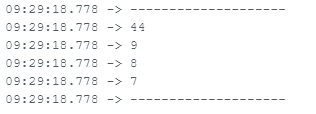
Here is the output that is expected.

 Program D:\Arduino_projects\SPI_Multiple_Buses\SPI_Multiple_Buses.ino compiled on Jan 25 2024 at 10:24:38
----RESET----
Initialising..........
3
10
9
8

15
13
12
14

MOSI:10
MISO: 9
SCK:  8
SS:   3
----------------------------------------------------------------------------------------------------------------------------------
----------------------------------------------------------------------------------------------------------------------------------
Manufacturer ID: efh
Memory Type: 40h
Capacity: 14h
JEDEC ID: ef4014h
----------------------------------------------------------------------------------------------------------------------------------

HTH
GL :slight_smile: PJ

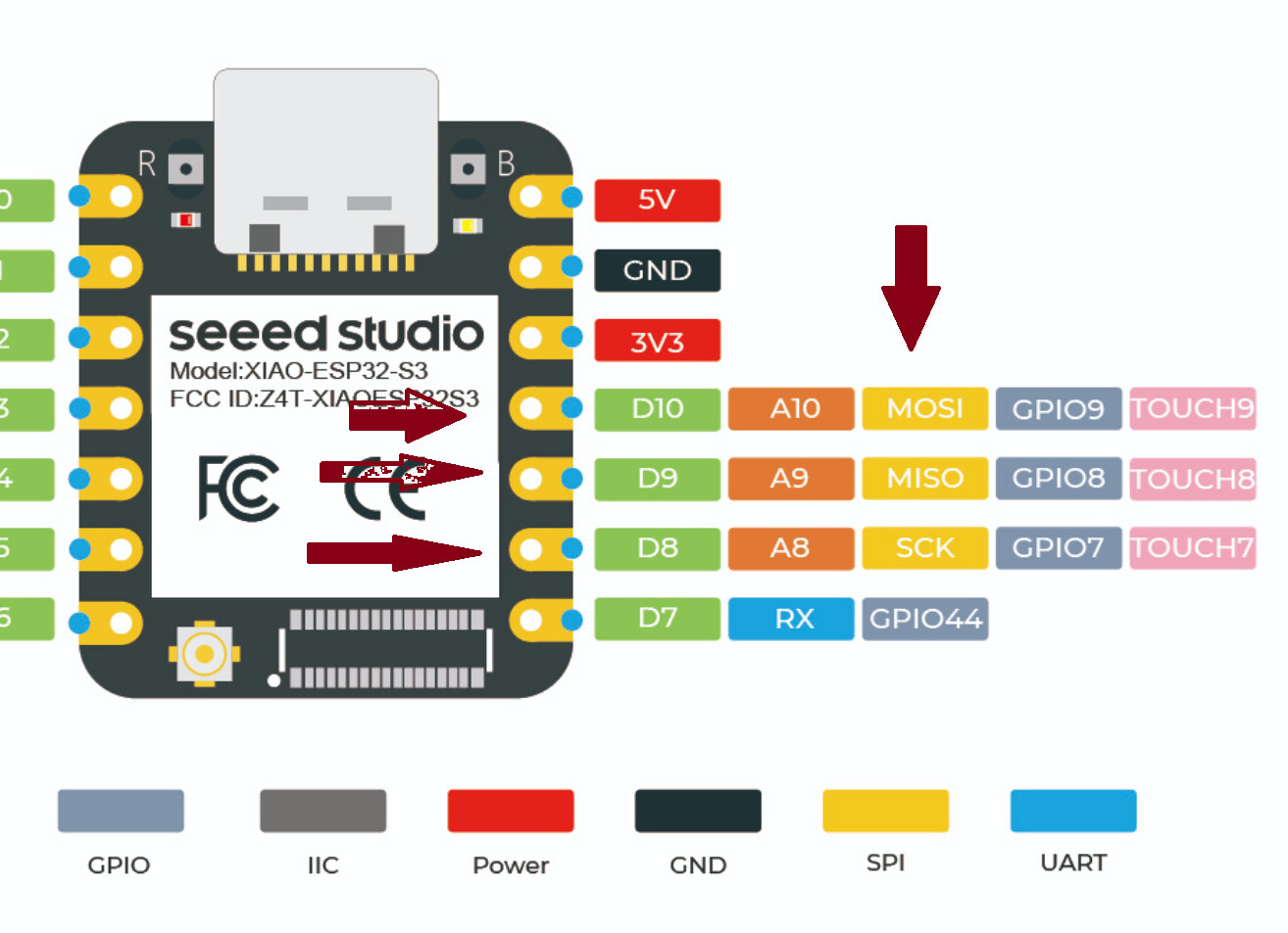
ALso for a long shot can you set the CS pin to pin 7(which is GPIO44)
try that fist with no other pin defines , then try with the others(correct ones) defined 8,9,10.
LMK

Hi,
In short it does not work. I tried with 10, 9, 8. I have also tried on ESP32-WROOM-32 (with other corrected pins). SPI does not work on ESP-IDF, does not work on Arduino.
I connected BMP280 chip which can measure temperature over I2C and SPI to XIAO ESP32S3, later to ESP32-WROOM-32. Last test I made :

  • BMP280 with XIAO ESP32S3 connected to I2C - WORKS
  • BMP280 with XIAO ESP32S3 connected to SPI pin 9,8,7 - DOES NOT WORK
  • BMP280 with XIAO ESP32S3 connected to SPI pin 10,9,8 - DOES NOT WORK
  • BMP280 with XIAO ESP32-WROOM-32 connected to I2C - WORKS
  • BMP280 with XIAO ESP32-WROOM-32 connected to HSPI - DOES NOT WORK
  • BMP280 with XIAO ESP32-WROOM-32 connected to VSPI - DOES NOT WORK

The same behavior on ESP-IDF and Arduino. Code for Arduino is simple and you will find it below.

#include <Wire.h>

#include <SPI.h>

#include <Adafruit_Sensor.h>

#include “Adafruit_BME280.h”

#define BME_SCK 14

#define BME_MISO 12

#define BME_MOSI 13

#define BME_CS 15

//SPI

Adafruit_BME280 bme(BME_CS, BME_MOSI, BME_MISO, BME_SCK);

//I2C

//Adafruit_BME280 bme;

void setup() {

unsigned status;

status = bme.begin(0x76);

//status = bme.begin();

if (!status) {

    printf("Could not find a valid BME280 sensor, check wiring, address, sensor ID!");

    printf("SensorID was: %u\n", bme.sensorID());

}

}

void loop() {

printf(“Temperature = %f\n”,bme.readTemperature());

delay(1000);

}

I have a LoRa module hooked up to an XIAO ESP32S3 Sense board, I have code that use the LoRa module for long range image transfers.

The SPI pins on the LoRa module are connected as per the XIAO ESP32S3 pinout and I initialise the SPI with;

SPI.begin();

Works for me, no need to define SPI pins or stuff like that.

Hi,
Did you have to cut path or solder pins like Pin Multiplexing | Seeed Studio Wiki
Default pins for XIAO ESP32s3 on Arduino are 9,8,7,44. Can you confirm?

Nope, no need for stuff like that.

Like I said, I just used the SPI pins on the ESP32S3 pinout.

The other pins for the LoRa module itself were for my board;

#define DIO0 D1               //DIO0 pin on LoRa device, used for sensing RX and TX done
#define NSS D3                //select on LoRa device
#define NRESET D0             //reset pin on LoRa device

I understand. When you right click on D1 for example and click “Go to definition” you will receive numbers.D0=1, D1=2, etc. What you have got for MOSI, MISO,SCK and SS?

No “Go to definition” here, using IDE 1.8.13

Hi there,
You need to use the </> tag for proper code display , that looks not good, as I said b4 It’s the pins and the way you assign the spi bus being used, also when ever you use a custom spi config you should use the CS as the begin.
ie. “begin flash (cs);”
HTH
GL :slight_smile: PJ