Hi,
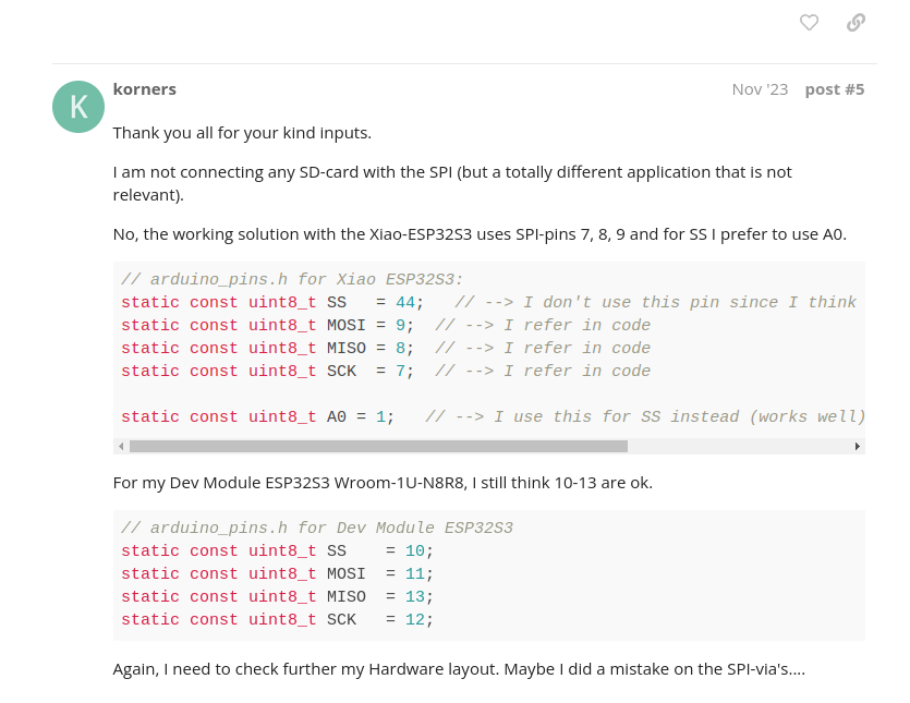
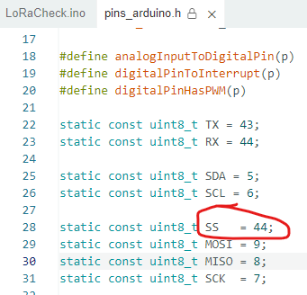
I have found the issue. Problem is SS line - Pin 44. Lora app works because SS line is on D3. When I have changed SS line, everything starts working.
I have found this https://forum.arduino.cc/t/spi-does-not-work-on-esp32s3-wroom-1u-n8r8/1184936/4
Hi there,
Good find, However the attachment is ok when going by the (iopin) for the Xiao ,The CS or SS is always the culprit.
(I always use the first 4 pins D0-D3 for stuff like that, btw)
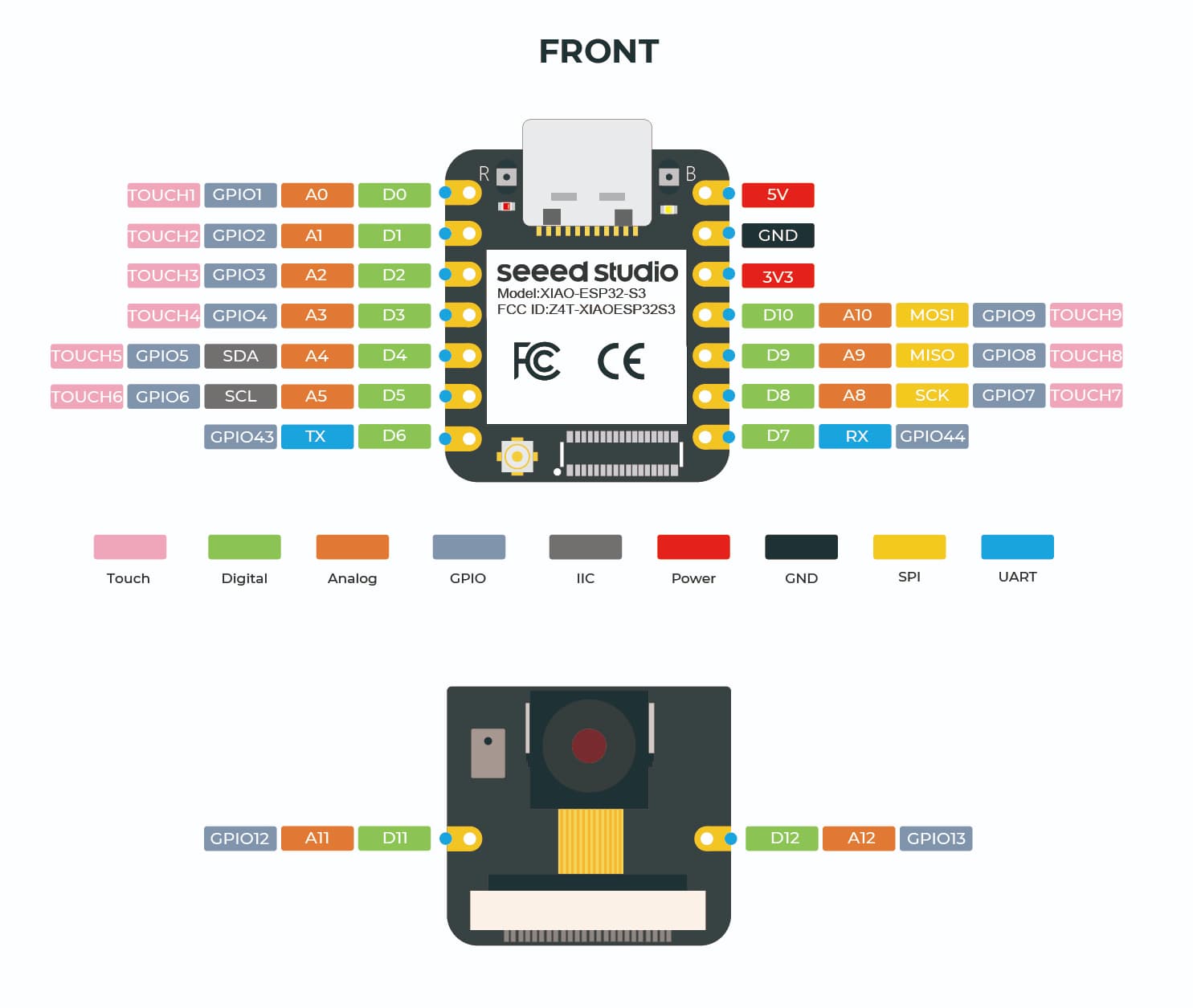
You can clearly see the pins are 8,9,10 (SCK,MISO,MOSI)
Gpio numbers are 7,8,9
If you run the SPI_Buss software it will tell you what they are…without any defines first , then You do not even need to define them only the SS. if you get that.
HTH
GL
How about check the shoulder job on the pins for an… error…
Hi PJ,
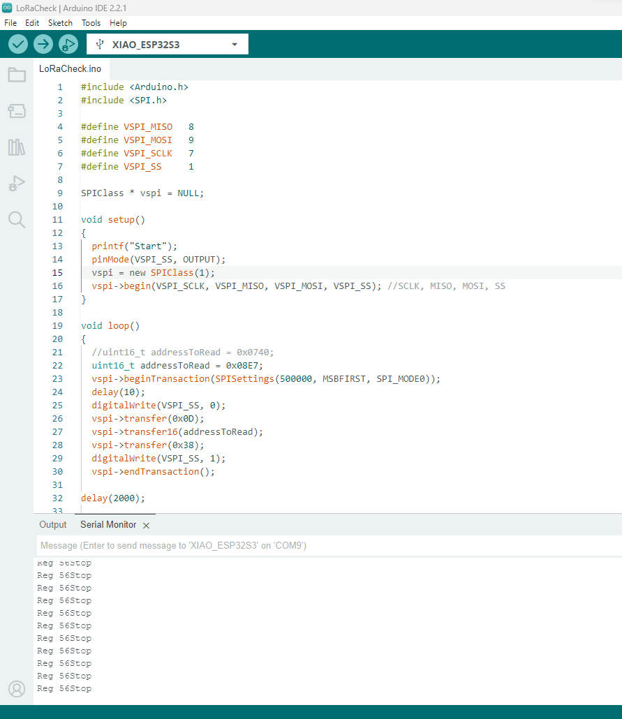
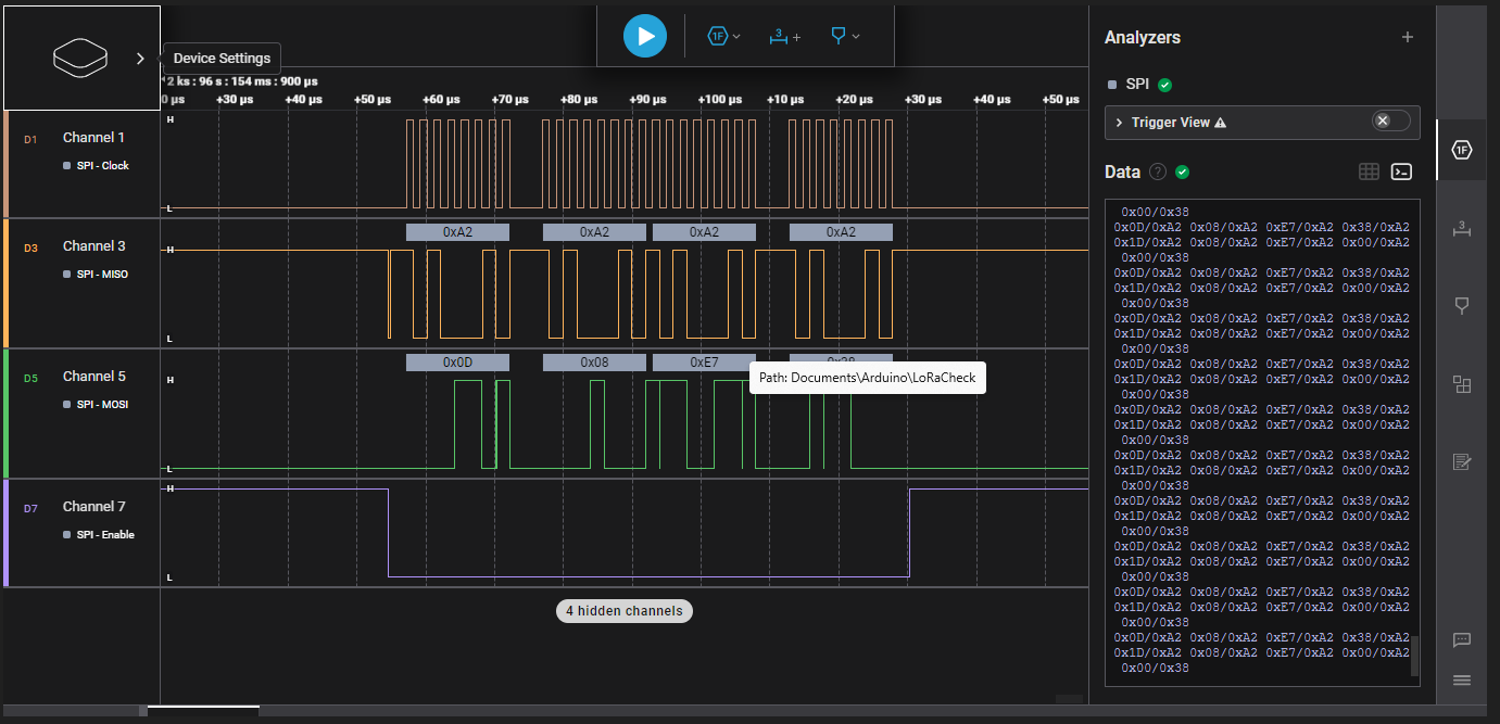
Please do not confuse people on forum 8,9,10 ARE NOT pin numbers and are incorrect for ES32S3 SPI. ESPs do not use pin numbers (when I write drivers for other processors, real processors pin numbers are used). Anyway ESPs use GPIOs numbers which are 7, 8, 9. I have just connected LoRa, I use 7,8,9 and I have got correct readings which you can CLEARLY see on the screenshot.
Screenshot from logic analyzer
Maybe you use fist GPIOs, but I have just started using ESP32, so I was relaying on documentation and header file. Default GPIO is 44 which you can CLEARLY see in the file
Not sure there is any significance to what the default for SS might be, I dont recall a library that uses SPI which does not allow you to specify whatever SS you want to use.
Its less confusing for me to stick to the XIAO D0 - D10 pin numbering, then a sketch would be common across the range of XIAOs.
HI There,
lol, ![]() Seems as though it’s YOU that’s having the problem, I know how the ESP32 SPI busses work, they are NOT all the same PERIOD. I Have demos on here to prove that .It’s easy for folks to get confused when in some cases GPIO’s vs. PIN numbers can be switched.
Seems as though it’s YOU that’s having the problem, I know how the ESP32 SPI busses work, they are NOT all the same PERIOD. I Have demos on here to prove that .It’s easy for folks to get confused when in some cases GPIO’s vs. PIN numbers can be switched.
The CS or SS can and is defined when not using the canned spi interface.
You should have a read of this link it will educate you on the subject maybe clear up the confusion you have.
HTH
GL ![]() PJ
PJ ![]()
Hi,
Of course can be defined. I have just done it in source code I have changed 44 to 1. Link you have sent me returns default values from header file I made screenshot from.
I have written response because you said “You can clearly see the pins are 8,9,10 (SCK,MISO,MOSI)”. Again this is incorrect for ESP32S3. I have just looked at ESP32C3 documentation and for ESP32C3 8, 9 ,10 are correct.
7,8,9 for ESP32S3
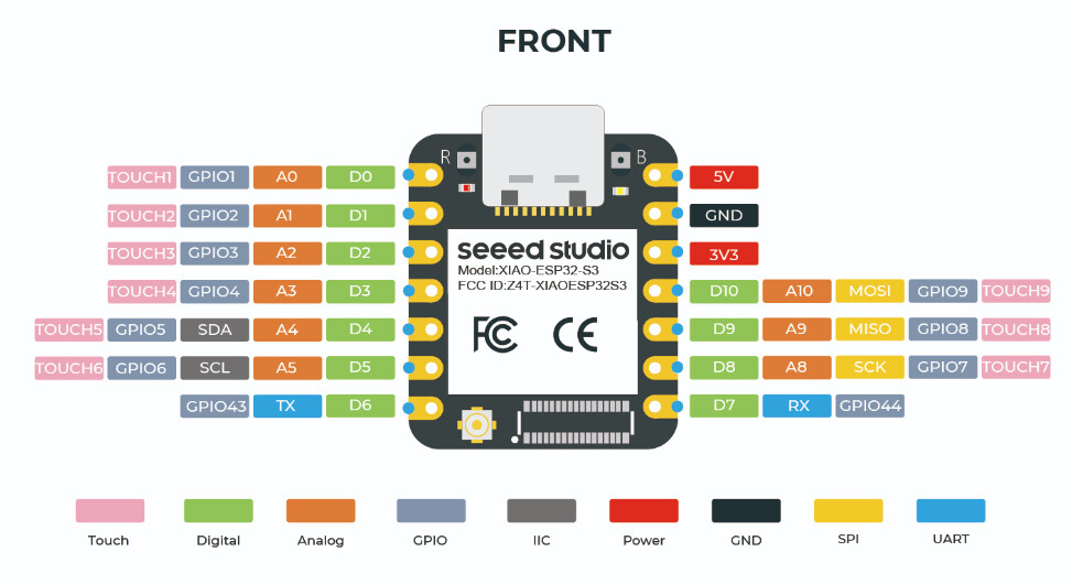
8,9,10 for ESP32C3

Hi there,
Yes now you get it, They are different for each variant , this thread is the ESP32S3 say’s so right in the tittle.
Glad you got it figured out and working, that’s what matters.
GL ![]() PJ
PJ ![]()
Iam get it??? ![]()
![]()
![]() I was trying to explain you 2 posts ago, that your suggested 8, 9, 10 for ESP32S3 are wrong
I was trying to explain you 2 posts ago, that your suggested 8, 9, 10 for ESP32S3 are wrong ![]()
![]()
![]() Good you get it that configuration for ESP32S3 and ESP32C3 are different. Cheers anyway.
Good you get it that configuration for ESP32S3 and ESP32C3 are different. Cheers anyway.
Hi there,
Yes, I see You do understand NOW , Very Good that’s the whole purpose of the forum.
GL ![]() PJ
PJ
I have understood this from the beginning. I have got your original post (before you edited the post). I do not think you understand difference between processor pins which you can find on esp design (screenshot below) and D1 D2, … which is only definition for Digital. I can add to definition BLEBLE1, BLEBLE2, but it does not mean it is pin numbers. Usually everything would be based on physical pins. But ESP family is based on GPIOs number (it does not mean GPIOs are physical pins).

You are correct, The Pins Multiplexing of the ESP32 is like magic if you know how it works.
Now you do ![]()
GL ![]() PJ
PJ
I know very well. I think STM32 (CUBE IDE) has got better solution. Now, you have educated yourself and you see the difference ![]()