Yes, this is an important note! In tests, I’ve found that current with Led Off is around 600uA (at 5V).
1 Like
Driving the WS at 5V actually requires a level shifter between the XIAO and the WS, which is a bit of a hassle.
Correct. That is “normal practice” for mosfet switches…
Depending on the project and power requirements I tend to use a “smart” switch, viz RT9742… low(ish) cost but with built in protection and 100nA standby current.
@grobasoz @msfujino thank you both for the input! I got some P-channel mosfets and they fixed the issue for me. I’m now seeing 2.4uA in deep sleep.
With the LED disabled and connected to a device over BLE, I am seeing about 390uA - does that sound reasonable or might there be more power savings on the table?
The LED seems to be working fine off 3.3V, could running it off the 3v3 pin lead to any issues down the line on either the LED side or nRF side?
1 Like
Excellent news! I have had the WS2812’s running fine with a 3V3 supply but that is “out of specified parameters” as mentioned by @msfujino.
@msfujino will also be able to answer the standby power consumption ![]()
The following links may be helpful.
’ System_ON_Sleep of XIAO BLE - #31 by msfujino
2 Likes
Hi all - I have read through some of the power consumption threads related to sleep and am looking for a list of what is actually being disabled behind the scenes. The reason is, I am using a rust-based library, ArielOS, with my xiao nrf52840 plus so I am trying to reproduce the power savings provided in the Arduino world, but that means I need to disable some things on my own (presumably just replicate whatever the sleep functions are doing in the Arduino libraries). Currently my code only draws 7uA avg on my nrf52840dk, but the same code on my xiao draws ~600uA so trying to find the “extras” that I need to disable. Thanks!
Hi cgc17, I have some questions.
- Where on XIAO are you applying what voltage to measure the current?
- Have you tried the method described in the attachment Flash_Light_Deep_Sleep.zip in Post #1?
- Please tell us the method you are implementing when the current is 600uA.
Thanks for your reply!
- I am supplying 3V to the 3v3 pin directly with ppk2
- Not yet, it looks like primarily it is disabling the QSPI flash which I will work out how to do on my side. Is it likely that the flash is taking up ~550uA or more?
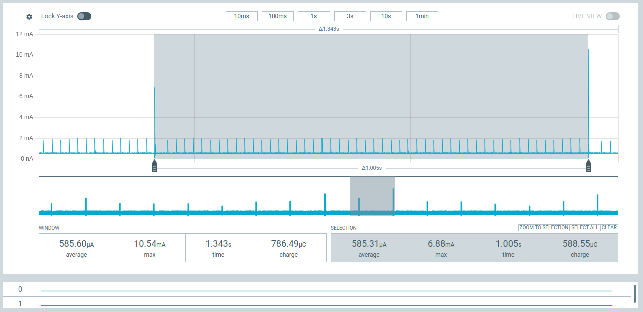
- I have a simple sleep loop - sleep for 1s, wakeup, go back to sleep.
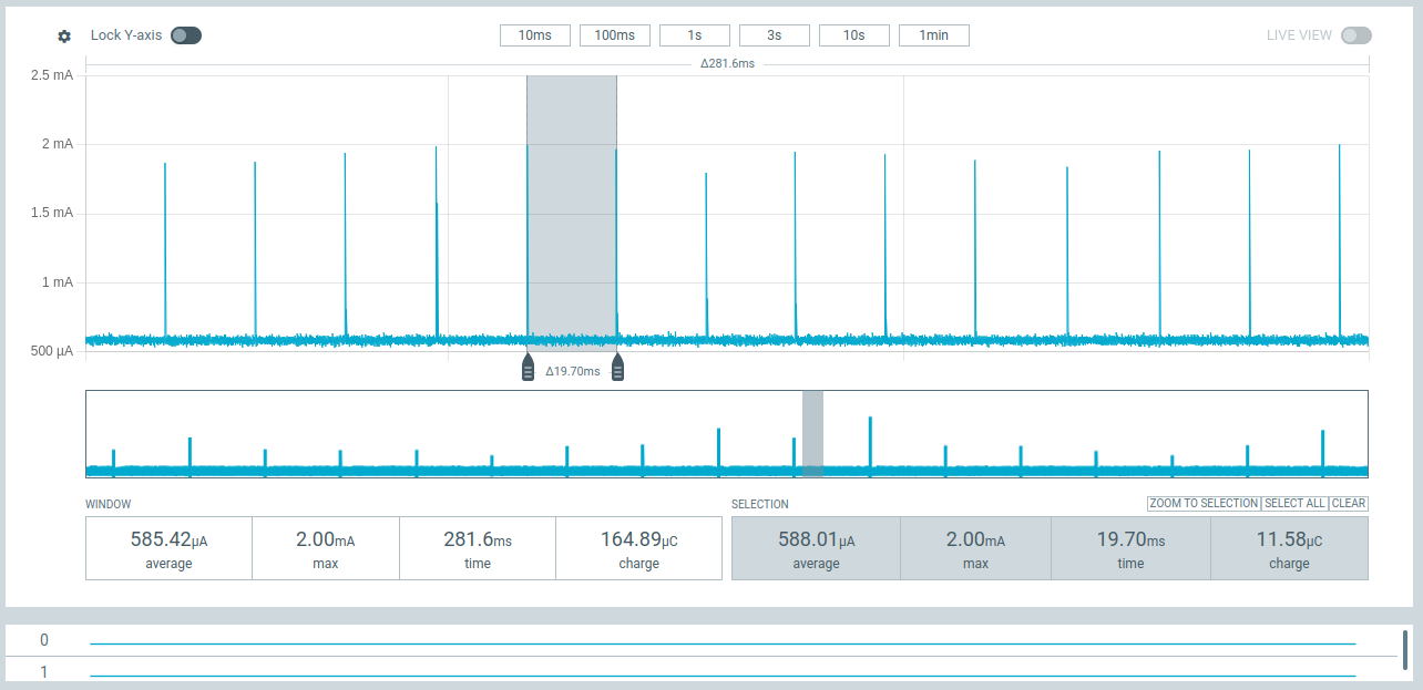
Here are 2 screenshots for the Xiao (first one I highlighted 1 second, and the second one I zoomed in to highlight the 20ms spikes and just to show that the baseline is > 500uA):
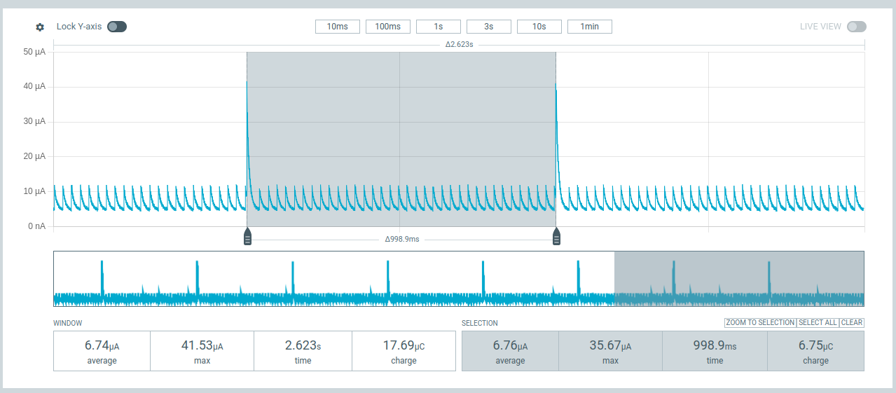
And here is one showing the same code running on the nrf52840dk:
And this may not really be that useful, but just to show the simplicity of the code I’m using to test:
#![no_main]
#![no_std]

use ariel_os::time::Timer;

#[ariel_os::task(autostart)]
async fn main() {
    loop {
        Timer::after_millis(1000).await;
    }
}
Hi there,
If you look at those threads closely , You will see the Vbat needs to be 3.6-3.85vDC from the battery so set your PPK2 accordingly and you will see the same numbers as you disable Flash, LDo , GPIO’ ,etc.
HTH
GL ![]() PJ
PJ ![]()
- Is REG1 set to DCDC mode?
- The flash memory current is at most 20uA.
- I have absolutely no idea why the current is lower with the same code on the nRF52840DK.
- On the Arduino nRF52840, the RTOS should be minimizing system activity during sleep via delay(). You might need to analyze the RTOS delay() function.
thanks for the replies. I’ve decided to switch over to arduino since there is support for the Xiao out of the box (plus I need the LPCOMP from nrf.h) and so that I can interact better with the community here using similar setups! so with that I can work with the code already provided above… if I have any issues I will post along with the sketch for review, but I imagine it should just work now. thank you for that @msfujino ![]()
I have just started working with this board and do not have much experience with the XIAO boards. Even after applying the codes provided above by @msfujino, I am unable to achieve the expected low power consumption (around 5 µA).
When I use the code exactly as provided by msfujino, I do get a current consumption of less than 5 µA. However, when I modify the code for my own use case, the current consumption in sleep mode becomes significantly higher.
From my observations, the issue occurs when I add the Bluefruit library and actually use it to connect to a device and send data. Simply including the library does not cause the problem, but when I initialize and use it in the setup (for example using statements like Bluefruit.begin(), Bluefruit.setName(), etc.), the current consumption during deep sleep increases drastically to around 9–10 mA. I think i am not correctly closing the ble connection or something.
If someone could provide or point me to a basic example where deep sleep is implemented along with BLE (not just including the library, but actually using BLE), it would be very helpful. I believe such an example exists somewhere in the forum, but I may have missed it.
Thanks in advance.
In the attachment to Post #1 of this thread, there is a sketch showing how the peripheral and central units communicate. You might find it helpful.
1 Like
Thank you so much @msfujino. Your code in the above attachment helped me in reducing my current consumption in deep sleep to 4-5 micro amps.
2 Likes
Hi everyone,
I’m working with a Seeed XIAO nRF52840 Sense and trying to understand if there is any practical way to reduce the sleep current when using the LSM6DS3 INT1 as the wake source.
Hardware / tools
- Board: XIAO nRF52840 Sense (LSM6DS3)
- Arduino core: Seeed nRF52 Boards v1.1.12
- Measurement tool: Nordic PPK2 in Source Meter mode, connected directly to 3V3 and GND (USB disconnected)
Goal
I’m trying to reach tens of µA in deep sleep while still being able to wake up from SYSTEM OFF using the LSM6DS3 motion/wake interrupt on INT1.
What I measured so far
1) Baseline deep sleep (SYSTEM OFF): ~20 µA
Using a minimal sketch that goes straight to SYSTEMOFF:
#include <Arduino.h>
#include "nrf.h"

void setup() {
  pinMode(LED_BUILTIN, OUTPUT);
  digitalWrite(LED_BUILTIN, HIGH);

  delay(50);

  NRF_POWER->SYSTEMOFF = 1;
  while (1) {}
}

void loop() {}
This gives a stable ~20 µA, so the board baseline looks good.
2) SYSTEM OFF + IMU wake interrupt: ~184 µA
When I configure the LSM6DS3 to generate a wake-up interrupt on INT1 and then enter NRF_POWER->SYSTEMOFF, I consistently measure around ~184 µA in sleep.
I already tried:
- disabling gyro (
CTRL2_G = 0x00) - lowering accel ODR down to 12.5/13 Hz (almost no change; ~184 µA → ~183 µA)
- current stays ~184 µA as long as the IMU wake interrupt is enabled
3) If I disable the interrupt routing: ~24 µA
If I set:
LSM6DS3_ACC_GYRO_MD1_CFG = 0x00(no interrupt routed to INT1)
I obviously lose the wake interrupt, but the sleep current drops to around ~24 µA.
So basically, enabling IMU wake adds ~160 µA compared to the baseline.
Question
Is there anything else I can do (register config / low-power mode / embedded-function settings) to keep the LSM6DS3 wake interrupt but reduce the sleep current below ~184 µA?
At this point it looks like the current is dominated by the IMU being kept “always-on” for wake detection, but I wanted to confirm if there is a lower-power wake mode I’m missing (either on the LSM6DS3 side or XIAO Sense board side).
Minimal code (simplified)
Below is a simplified version of what I’m doing (setup + IMU sleep config + SYSTEMOFF with GPIO sense on INT1). This is not my full application code, just the relevant part for sleep current:
#include <Arduino.h>
#include <Wire.h>
#include "LSM6DS3.h"
#include "nrf_gpio.h"
#include "nrf.h"

#define IMU_POWER_PIN PIN_LSM6DS3TR_C_POWER
#define INT1_PIN      PIN_LSM6DS3TR_C_INT1

LSM6DS3 myIMU(I2C_MODE, 0x6A);

static void imu_config_sleep_wake_int1()
{
  // Disable routing first
  myIMU.writeRegister(LSM6DS3_ACC_GYRO_MD1_CFG, 0x00);

  // Gyro OFF, Accel OFF
  myIMU.writeRegister(LSM6DS3_ACC_GYRO_CTRL2_G, 0x00);
  myIMU.writeRegister(LSM6DS3_ACC_GYRO_CTRL1_XL, 0x00);

  delay(10);

  // Clear pending wake source
  uint8_t dummy;
  myIMU.readRegister(&dummy, LSM6DS3_ACC_GYRO_WAKE_UP_SRC);

  delay(10);

  // Wake-up config
  myIMU.writeRegister(LSM6DS3_ACC_GYRO_WAKE_UP_THS, 0x01);
  myIMU.writeRegister(LSM6DS3_ACC_GYRO_WAKE_UP_DUR, 0x01);

  // This seems required in my setup, otherwise INT1 wake doesn't work
  myIMU.writeRegister(LSM6DS3_ACC_GYRO_TAP_CFG1, 0x80);

  // Accel ON @ 12.5/13 Hz (ODR_XL_13Hz)
  myIMU.writeRegister(LSM6DS3_ACC_GYRO_CTRL1_XL, 0x10);

  delay(50);

  // Clear transients
  myIMU.readRegister(&dummy, LSM6DS3_ACC_GYRO_WAKE_UP_SRC);
  myIMU.readRegister(&dummy, LSM6DS3_ACC_GYRO_WAKE_UP_SRC);

  delay(10);

  // Route wake-up interrupt to INT1
  myIMU.writeRegister(LSM6DS3_ACC_GYRO_MD1_CFG, 0x20);
}

static void systemoff_wake_on_int1()
{
  // Clear PORT event and prepare for sense
  NRF_GPIOTE->EVENTS_PORT = 0;
  __SEV(); __WFE(); __WFE();

  // Configure GPIO sense so INT1 HIGH wakes from SYSTEMOFF
  uint32_t pin_number = g_ADigitalPinMap[INT1_PIN];
  nrf_gpio_cfg_sense_input(pin_number,
                           NRF_GPIO_PIN_PULLDOWN,
                           NRF_GPIO_PIN_SENSE_HIGH);

  NRF_POWER->SYSTEMOFF = 1;
  while (1) {}
}

void setup()
{
  // Keep LEDs off
  pinMode(LED_BUILTIN, OUTPUT);
  digitalWrite(LED_BUILTIN, HIGH);

  // IMU power ON
  pinMode(IMU_POWER_PIN, OUTPUT);
  digitalWrite(IMU_POWER_PIN, HIGH);
  delay(50);

  // I2C
  Wire.begin();
  Wire.setClock(400000);

  // IMU init
  myIMU.settings.gyroEnabled = 1;
  myIMU.begin();

  pinMode(INT1_PIN, INPUT);

  // Configure IMU for wake on INT1 and go to SYSTEMOFF
  imu_config_sleep_wake_int1();
  delay(100);
  systemoff_wake_on_int1();
}

void loop() {}
Any advice would be appreciated (especially if there is a known lower-power wake configuration for LSM6DS3 on the XIAO Sense, or if ~180 µA is simply expected for wake-on-motion with this IMU).
Thanks!
Hi there,
So, If you look at the Technical Reference Guide PDF (not in the data sheet PDF) theirs some power saving for level triggered vs edge triggered on the interrupt pin, for One.
Are you sleeping the Whole way ? DEEP or Light , Everything, Flash too ?
You may find the demos I have posted on Wake, Sleep, PARK, and interrupt IMU as well as Drop, Motion and Fall Detection modes and techniques.
Your pretty close to the bottom but I believe there is some more depth attainable. ![]()
![]()
Keep Going.
HTH
GL ![]() PJ
PJ ![]()
2 Likes
Hey Guys i have a Problem:
I am currently having a problem with deep sleep.
At the moment, I am programming with ChatGPT and Codex, but I cannot find a solution to this issue. I am using a voltage divider with 100 kΩ resistors, but my sketch is still drawing around 0.4 mA, which is far too high.
this is the sketch:
#include <Arduino.h>
#include <ArduinoBLE.h>
#include <Wire.h>
#include “LSM6DS3.h”
#include <math.h>
#include <nrf_gpio.h>

static const uint8_t SENSOR_ID = 1;

static const uint32_t SEND_MS = 500;
static const uint32_t BATT_MEASURE_MS = 5000;
static const uint32_t CHARGE_WAIT_CHECK_MS = 10000;
static const uint32_t SLEEP_HOLD_MS = 3000;

static const uint16_t LOW_BATT_SLEEP_MV = 3650;
static const uint16_t LOW_BATT_LED_MV   = 3730;
static const uint16_t RESUME_BATT_MV    = 3800;

// Complementary Filter
static const float ALPHA = 0.985f;
static const float SMOOTH_ALPHA = 0.18f;

// 100k / 100k Spannungsteiler => Faktor 2.0
static const int BAT_PIN = A0;
static const float ADC_REF_V = 3.3f;
static const float BAT_DIVIDER_FACTOR = 2.0f;
static const float BAT_CAL_FACTOR = 1.00f;
static const int ADC_MAX = 4095;

// Externe LEDs
static const int LED_BLUE_PIN  = A1;
static const int LED_RED_PIN   = A2;
static const int LED_GREEN_PIN = A3;

// Taster: D5 → Taster → GND
static const int BUTTON_PIN = D5;

static const uint8_t FLAG_CHARGING = 0x01;

LSM6DS3 imu(I2C_MODE, 0x6A);

struct attribute((packed)) AdvPacket {
uint8_t magic1;
uint8_t magic2;
uint8_t version;
uint8_t id;
int16_t angle_ddeg;
uint16_t batt_mv;
uint16_t seq;
uint8_t flags;
};

enum SensorMode {
MODE_NORMAL = 0,
MODE_CHARGE_WAIT = 1
};

static SensorMode currentMode = MODE_NORMAL;

static uint16_t seqNo = 0;
static uint32_t nextSendMs = 0;
static uint32_t nextBattMs = 0;
static uint32_t nextChargeCheckMs = 0;
static uint32_t lastFilterUs = 0;

static float pitchDeg = 0.0f;
static float smoothPitchDeg = 0.0f;
static bool filterInitialized = false;
static bool imuReady = false;
static float gyroOffsetY = 0.0f;
static uint16_t batteryMv = 0;

volatile bool buttonPressed = false;

void buttonISR() {
buttonPressed = true;
}

static void blinkInternalLed(uint8_t ledPin, int times, int delayMs) {
pinMode(ledPin, OUTPUT);
for (int i = 0; i < times; i++) {
digitalWrite(ledPin, LOW);   // interne RGB ist active-low
delay(delayMs);
digitalWrite(ledPin, HIGH);
delay(delayMs);
}
}

static void internalRgbOff() {
pinMode(LED_RED, OUTPUT);
pinMode(LED_GREEN, OUTPUT);
pinMode(LED_BLUE, OUTPUT);

digitalWrite(LED_RED, HIGH);
digitalWrite(LED_GREEN, HIGH);
digitalWrite(LED_BLUE, HIGH);
}

static void parkInternalRgb() {
internalRgbOff();

nrf_gpio_cfg_sense_input(digitalPinToPinName(LED_RED),   NRF_GPIO_PIN_PULLUP, NRF_GPIO_PIN_NOSENSE);
nrf_gpio_cfg_sense_input(digitalPinToPinName(LED_GREEN), NRF_GPIO_PIN_PULLUP, NRF_GPIO_PIN_NOSENSE);
nrf_gpio_cfg_sense_input(digitalPinToPinName(LED_BLUE),  NRF_GPIO_PIN_PULLUP, NRF_GPIO_PIN_NOSENSE);
}

static void ledsOff() {
digitalWrite(LED_BLUE_PIN, LOW);
digitalWrite(LED_RED_PIN, LOW);
digitalWrite(LED_GREEN_PIN, LOW);
}

static void setLedNormal() {
digitalWrite(LED_BLUE_PIN, LOW);
digitalWrite(LED_RED_PIN, LOW);
digitalWrite(LED_GREEN_PIN, HIGH);
}

static void setLedCharging() {
digitalWrite(LED_BLUE_PIN, HIGH);
digitalWrite(LED_RED_PIN, LOW);
digitalWrite(LED_GREEN_PIN, LOW);
}

static void setLedLowBattery() {
digitalWrite(LED_BLUE_PIN, LOW);
digitalWrite(LED_RED_PIN, HIGH);
digitalWrite(LED_GREEN_PIN, LOW);
}

static void parkBoardPinsForSleep() {
pinMode(LED_BLUE_PIN, INPUT);
pinMode(LED_RED_PIN, INPUT);
pinMode(LED_GREEN_PIN, INPUT);
pinMode(A0, INPUT);

#ifdef PIN_VBAT_ENABLE
pinMode(PIN_VBAT_ENABLE, OUTPUT);
digitalWrite(PIN_VBAT_ENABLE, HIGH);
#endif

#ifdef VBAT_ENABLE
pinMode(VBAT_ENABLE, OUTPUT);
digitalWrite(VBAT_ENABLE, HIGH);
#endif

#ifdef PIN_CHARGING_CURRENT
pinMode(PIN_CHARGING_CURRENT, INPUT);
#endif

#ifdef PIN_LSM6DS3TR_C_POWER
pinMode(PIN_LSM6DS3TR_C_POWER, OUTPUT);
digitalWrite(PIN_LSM6DS3TR_C_POWER, LOW);
#endif

#ifdef PIN_PDM_PWR
pinMode(PIN_PDM_PWR, OUTPUT);
digitalWrite(PIN_PDM_PWR, LOW);
#endif

#ifdef PIN_QSPI_CS
pinMode(PIN_QSPI_CS, INPUT_PULLUP);
#endif
#ifdef PIN_QSPI_SCK
pinMode(PIN_QSPI_SCK, INPUT);
#endif
#ifdef PIN_QSPI_IO0
pinMode(PIN_QSPI_IO0, INPUT);
#endif
#ifdef PIN_QSPI_IO1
pinMode(PIN_QSPI_IO1, INPUT);
#endif
#ifdef PIN_QSPI_IO2
pinMode(PIN_QSPI_IO2, INPUT);
#endif
#ifdef PIN_QSPI_IO3
pinMode(PIN_QSPI_IO3, INPUT);
#endif
}

static float clampPitch(float deg) {
if (deg > 90.0f) return 90.0f;
if (deg < -90.0f) return -90.0f;
return deg;
}

static int16_t degToDdeg(float deg) {
float v = deg * 10.0f;
if (v > 900.0f) v = 900.0f;
if (v < -900.0f) v = -900.0f;
return (int16_t) lroundf(v);
}

static bool usbPresent() {
return (NRF_POWER->USBREGSTATUS & POWER_USBREGSTATUS_VBUSDETECT_Msk) != 0;
}

static uint8_t makeFlags(bool charging) {
uint8_t f = 0;
if (charging) f |= FLAG_CHARGING;
return f;
}

static uint16_t measureBatteryMv() {
const int samples = 32;
uint32_t sum = 0;

analogRead(BAT_PIN);
delay(2);

for (int i = 0; i < samples; i++) {
sum += analogRead(BAT_PIN);
delay(2);
}

float raw = sum / float(samples);
float vAdc = (raw * ADC_REF_V) / ADC_MAX;
float vBat = vAdc * BAT_DIVIDER_FACTOR * BAT_CAL_FACTOR;

if (vBat < 0.0f) vBat = 0.0f;
return (uint16_t) lroundf(vBat * 1000.0f);
}

static float readAccelPitchDeg() {
float ax = imu.readFloatAccelX();
float ay = imu.readFloatAccelY();
float az = imu.readFloatAccelZ();

float accPitch = atan2f(ax, sqrtf(ay * ay + az * az)) * 180.0f / PI;
return clampPitch(accPitch);
}

static void calibrateGyro() {
const int samples = 500;
float sum = 0.0f;

for (int i = 0; i < samples; i++) {
sum += imu.readFloatGyroY();
delay(2);
}

gyroOffsetY = sum / samples;
}

static bool initImuIfNeeded() {
if (imuReady) return true;

#ifdef PIN_LSM6DS3TR_C_POWER
pinMode(PIN_LSM6DS3TR_C_POWER, OUTPUT);
digitalWrite(PIN_LSM6DS3TR_C_POWER, HIGH);
delay(10);
#endif

if (imu.begin() != 0) {
Serial.println(“IMU Fehler”);
return false;
}

Serial.println(“Sensor still halten fuer Gyro-Kalibrierung…”);
delay(1000);
calibrateGyro();

pitchDeg = readAccelPitchDeg();
smoothPitchDeg = pitchDeg;
lastFilterUs = micros();
filterInitialized = true;
imuReady = true;
return true;
}

static void updatePitchFilter() {
uint32_t nowUs = micros();

if (!filterInitialized) {
pitchDeg = readAccelPitchDeg();
smoothPitchDeg = pitchDeg;
lastFilterUs = nowUs;
filterInitialized = true;
return;
}

float dt = (nowUs - lastFilterUs) / 1000000.0f;
lastFilterUs = nowUs;

if (dt <= 0.0f || dt > 0.1f) dt = 0.01f;

float gyroY = imu.readFloatGyroY() - gyroOffsetY;
float accelPitch = readAccelPitchDeg();

float gyroPitch = pitchDeg + gyroY * dt;
pitchDeg = ALPHA * gyroPitch + (1.0f - ALPHA) * accelPitch;
pitchDeg = clampPitch(pitchDeg);

smoothPitchDeg += SMOOTH_ALPHA * (pitchDeg - smoothPitchDeg);
smoothPitchDeg = clampPitch(smoothPitchDeg);
}

static void advertisePacket(int16_t angleDdeg, uint8_t flags) {
AdvPacket p;
p.magic1 = ‘W’;
p.magic2 = ‘H’;
p.version = 3;
p.id = SENSOR_ID;
p.angle_ddeg = angleDdeg;
p.batt_mv = batteryMv;
p.seq = seqNo++;
p.flags = flags;

BLE.stopAdvertise();
BLE.setManufacturerData((const uint8_t*) &p, sizeof(p));
BLE.advertise();
}

static void enterTrueSystemOff() {
BLE.stopAdvertise();
delay(20);

ledsOff();
internalRgbOff();
parkInternalRgb();
parkBoardPinsForSleep();

NRF_POWER->DCDCEN  = 1;
NRF_POWER->DCDCEN0 = 1;

delay(20);

nrf_gpio_cfg_sense_input(
digitalPinToPinName(BUTTON_PIN),
NRF_GPIO_PIN_PULLUP,
NRF_GPIO_PIN_SENSE_LOW
);

NRF_POWER->SYSTEMOFF = 1;

while (1) {
__WFE();
}
}

static void enterLowBatterySystemOff() {
setLedLowBattery();
delay(300);
enterTrueSystemOff();
}

static bool handleSleepButton() {
if (!buttonPressed) return false;
buttonPressed = false;

unsigned long pressStart = millis();
while (digitalRead(BUTTON_PIN) == LOW && millis() - pressStart < SLEEP_HOLD_MS) {
delay(10);
}

if (digitalRead(BUTTON_PIN) == LOW && millis() - pressStart >= SLEEP_HOLD_MS) {
blinkInternalLed(LED_RED, 2, 120);

while (digitalRead(BUTTON_PIN) == LOW) {
  delay(1);
}
delay(50);

enterTrueSystemOff();
return true;

}

return false;
}

static void switchToChargeWait() {
currentMode = MODE_CHARGE_WAIT;
nextChargeCheckMs = millis();
setLedCharging();
}

static void switchToNormal() {
if (!initImuIfNeeded()) return;

currentMode = MODE_NORMAL;
uint32_t now = millis();
nextSendMs = now + SEND_MS;
nextBattMs = now + BATT_MEASURE_MS;

setLedNormal();
advertisePacket(degToDdeg(smoothPitchDeg), makeFlags(usbPresent()));
}

static void evaluatePowerState(bool allowAdvertiseStatus) {
bool usb = usbPresent();

if (!usb && batteryMv <= LOW_BATT_SLEEP_MV) {
enterLowBatterySystemOff();
return;
}

if (usb && batteryMv < RESUME_BATT_MV) {
switchToChargeWait();
if (allowAdvertiseStatus) {
advertisePacket(0, makeFlags(true));
}
return;
}

switchToNormal();
}

void setup() {
Serial.begin(115200);
delay(300);

pinMode(BUTTON_PIN, INPUT_PULLUP);

while (digitalRead(BUTTON_PIN) == LOW) {
delay(1);
}
delay(50);

internalRgbOff();

if (NRF_POWER->RESETREAS & POWER_RESETREAS_OFF_Msk) {
NRF_POWER->RESETREAS = POWER_RESETREAS_OFF_Msk;
blinkInternalLed(LED_BLUE, 2, 120);
}

Wire.begin();

pinMode(BAT_PIN, INPUT);
analogReadResolution(12);

#ifdef PIN_CHARGING_CURRENT
pinMode(PIN_CHARGING_CURRENT, OUTPUT);
digitalWrite(PIN_CHARGING_CURRENT, LOW);
#endif

pinMode(LED_BLUE_PIN, OUTPUT);
pinMode(LED_RED_PIN, OUTPUT);
pinMode(LED_GREEN_PIN, OUTPUT);
ledsOff();

attachInterrupt(digitalPinToInterrupt(BUTTON_PIN), buttonISR, FALLING);

batteryMv = measureBatteryMv();

if (!BLE.begin()) {
setLedLowBattery();
while (1) {
delay(100);
}
}

BLE.setLocalName(“WinkelSensor”);
BLE.setDeviceName(“WinkelSensor”);

evaluatePowerState(true);
}

void loop() {
BLE.poll();

if (handleSleepButton()) {
return;
}

if (currentMode == MODE_NORMAL) {
updatePitchFilter();

uint32_t now = millis();

if ((int32_t)(now - nextBattMs) >= 0) {
  batteryMv = measureBatteryMv();
  nextBattMs = now + BATT_MEASURE_MS;

  bool usb = usbPresent();
  if ((!usb && batteryMv <= LOW_BATT_SLEEP_MV) || (usb && batteryMv < RESUME_BATT_MV)) {
    evaluatePowerState(true);
    return;
  }

  if (!usb && batteryMv <= LOW_BATT_LED_MV) {
    setLedLowBattery();
  } else {
    setLedNormal();
  }
}

if ((int32_t)(now - nextSendMs) >= 0) {
  advertisePacket(degToDdeg(smoothPitchDeg), makeFlags(usbPresent()));

  do {
    nextSendMs += SEND_MS;
  } while ((int32_t)(now - nextSendMs) >= 0);
}

delay(2);
return;

}

if (currentMode == MODE_CHARGE_WAIT) {
uint32_t now = millis();

if ((int32_t)(now - nextChargeCheckMs) >= 0) {
  batteryMv = measureBatteryMv();
  nextChargeCheckMs = now + CHARGE_WAIT_CHECK_MS;

  bool usb = usbPresent();

  if (!usb && batteryMv <= LOW_BATT_SLEEP_MV) {
    enterLowBatterySystemOff();
    return;
  }

  if (usb && batteryMv >= RESUME_BATT_MV) {
    switchToNormal();
    return;
  }

  setLedCharging();
  advertisePacket(0, makeFlags(usb));
}

delay(20);

}
}>
Hi there,
And welcome here…
So someone forgot to use the code tags ![]() above " </> " Paste it in there.
above " </> " Paste it in there.
makes it easier to read and test, you will get better quality help also that way.
just edit your post… Highlight the code then go press the button up top that looks like I said.
Now to the Code review and test. ![]()
HTH
GL ![]() PJ
PJ ![]()
Which BSP are you using ?
Can you describe the codes function? i.e blinks the LED and sleeps or what?
give us more? on battery or USB plugged in?
Is this on a custom board or just raw-dogging for test purposes, first ?
![]()
a picture is always acceptable too as currency here. As you’ll find there are a lot of provers’ with no pudding presented so to speak of. Text Only types ![]()
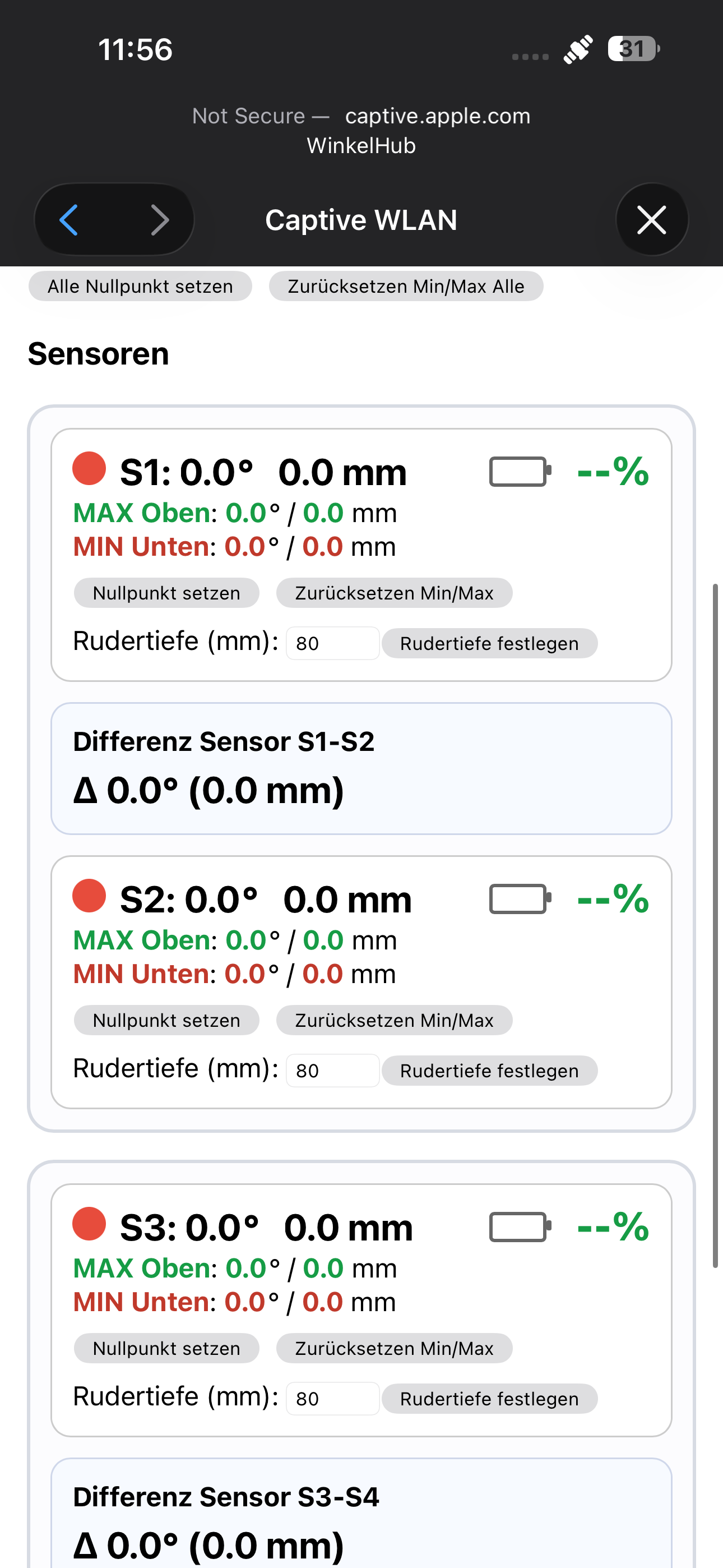
I am building a system consisting of a XIAO nRF52840 Sense as an angle sensor and an ESP32 hub. The sensor measures the angle using IMU data, sends it via BLE advertising, and the hub scans the sensors and displays the values in a web interface.
On the sensor side, the following points:
-
Gyroscope + accelerometer with a complementary filter
-
BLE manufacturer data for the angle value
-
Battery measurement via A0 with an external voltage divider
-
Charging and power logic
-
That works but i have Problems with the Deep sleep i dont know if i should use a coin Battery to power it or a lipo i whant to keep it simple and safe