Added it. Made an overlay for rfswctl being port2 pin 5. But no change. I cannot even keep my connection stable at more than 2m. What RSSI are others getting at 1m? I also just flashed a Xiao mg24 board with standard ble example. And same type of (extremely low) power
At 8dBm, the RSSI is around -40dBm at a distance of 10cm when using a ceramic antenna.
Why not go back to basics and try the sample on the Wiki?
edit:Below is a link to a sample I wrote. It might be helpful.
Thanks msfujino. Yes, let me try that example. But what RSSI are you seeing at 1 and 5m? I am just not getting stable connections. I am almost at the point of spending a week designing my own board using the copper trace antenna of the nordic development kit as a starting point. That has 30dB better power.
Edit: Trying to build the example. But seems nrf SDK5. I am using nrf Connect SDK. Not easy to migrate
Edit2. Managed to get it running. But tx power (during advertising) is still low. Here are my changes to the nRF54_BLE_PeripheralC code:
Removed:
-
All ADC code (includes, macros, variables, adc_init() function, battery voltage reading)
-
Unused regulator devices (pdm_imu_reg, vbat_reg)
-
Legacy nRF5 SDK headers (nrf.h, nrfx_power.h)
-
ADC configs from prj.conf (CONFIG_ADC, CONFIG_ADC_ASYNC)
-
zephyr,user node with io-channels from device tree overlay
Kept:
-
All Bluetooth functionality (GATT service, connection handling, RSSI, advertising, data TX/RX)
-
Essential GPIO (LED for status indication, RF switch for antenna control)
-
RF switch regulator (needed for Bluetooth antenna selection)
Changes:
-
Data packet size reduced from 16 to 14 bytes (removed 2-byte vbat field)
-
Fixed BT_LE_ADV_OPT_CONNECTABLE flag issue (not available in NCS v3.2.1, removed)
-
Simplified port_init() to only handle RF switch setup
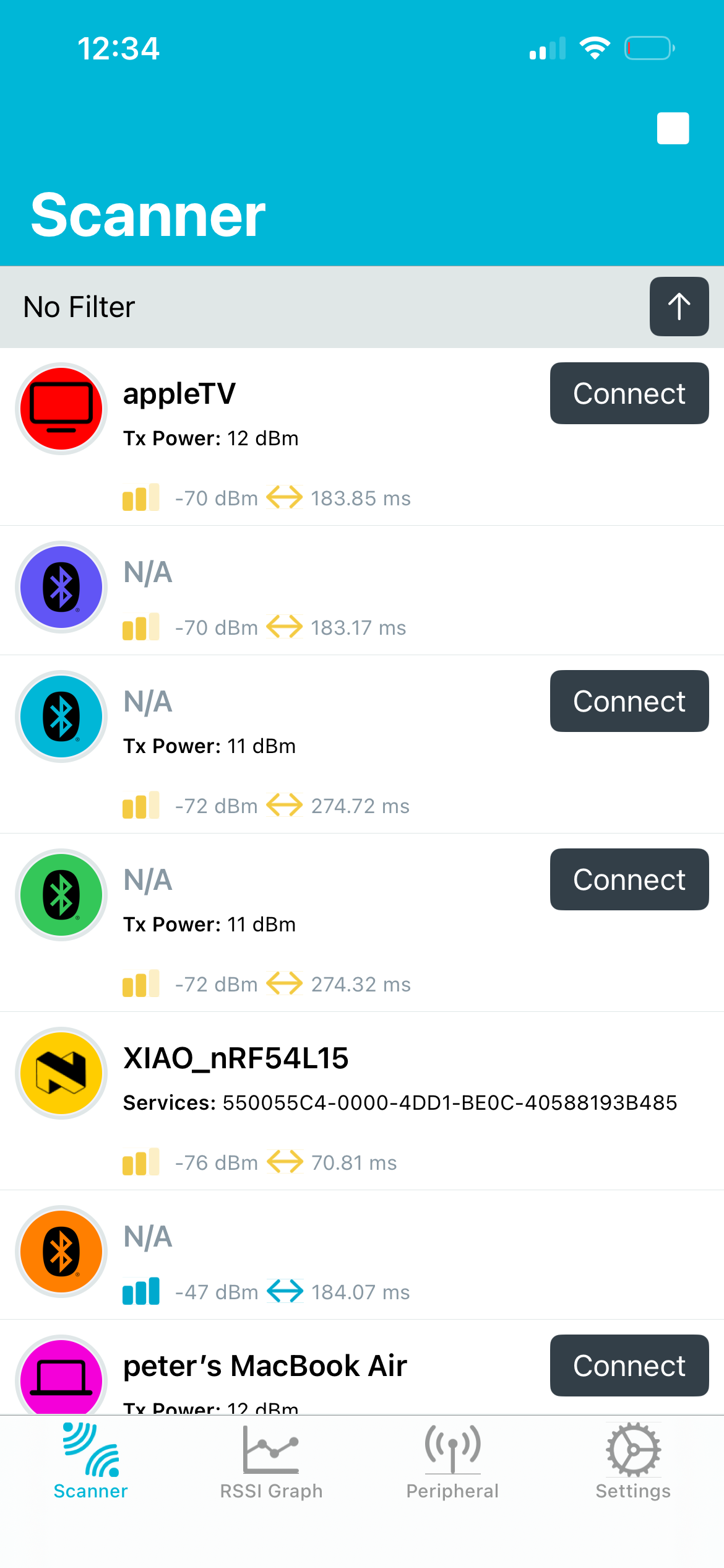
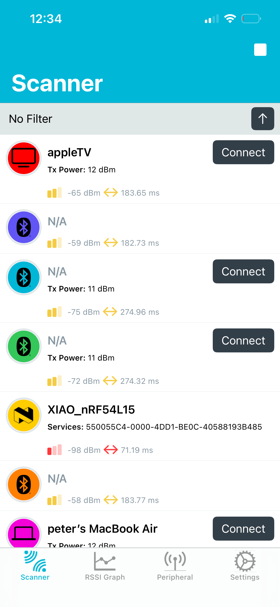
At 1 meter, it’s about -65 dBm. At 5 meters, it’s behind a wall, so it’s not very reliable, but it’s around -75 dBm.
Based on experience, communication remains stable down to about -90 dBm.
zephyr.zip (215.0 KB)
This is the zephyr.hex file created in the build environment below. It has been uploaded to XIAO_nRF54L15 and RSSI has been verified. For reference, RSSI values when changing rfsw on/off and antenna selection are also shown. RSSI was measured using the nRF_Connect app on an iPad. Based on these results, your XIAO_nRF54L15 may have an incorrectly configured rfsw.
// SDK: nRF Connect SDK v3.1.1
// Toolchain: nRF Connect SDK Toolchain v3.1.1
// seeedboards: zephyr version ~3.40201.251021
// board: xiao_nrf54l15/nrf54l15/cpuapp
rfsw=on, rfswctl=1
10cm -35 ~ -30dBm
1m -55 ~ -50dBm
5m -70 ~ -65dBm
rfsw=off, rfswctl=1
10cm -50 ~ -45dBm
1m -75 ~ -70dBm
5m -90 ~ -85dBm
rfsw=on, rfswctl=0
10cm -55 ~ -50dBm
1m -80 ~ -75dBm
5m -95 ~ -90dBm
1 Like
Would be interesting to contrast those results with a XIAO MG24?
1 Like
The antenna selection circuits for XIAO_nRF54L and XIAO_MG24 are identical, so they should show the same RSSI values.
1 Like
I tried building with NCSv3.2.1.
It seems the device tree has been rewritten so that:
err = gpio_pin_set_dt(&rfswctl, 0); // 0:onboard, 1:external
1 Like
Thank you! Trying to run your .hex first. Will then revisit err = gpio_pin_set_dt(&rfswctl, 0). The latter I had ran into in your earlier example and I had to define rfswctl manually (did it as port2 pin5 out of my head). Will post my results.
Update1: Flashed the zephyr.hex file and oh my God! -49dBm just laying 20cm from my laptop. This was 30dB worse. Just cannot believe it.
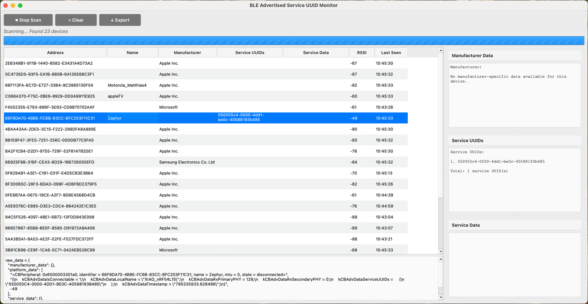
I use this ble-tools/ble_basic_scanner.py at main · RT-circuits/ble-tools · GitHub tool for my tests (reason being that I am interested in advertised service UUIDs and service data, both being different and this tool makes that distinction).
And at 5m distance where I was hitting -90 using my own code assuming that xioa specifics were handled by Zephyr, I now have…. -62! Will now continue with understanding what setting I didn’t do, even when you pointed me to it before (“did you read the wiki?”, “&rfswctl”).
Update2: Going back to my own code. Looking at XIAO schematic as well.
Update3: msfujino saved my project!! Thank you! Solution:
-
The RF switch for the antenna is not switched by one GPIO as you would expect, but by two. VDD of the switch is connected to GPIO2.03, the actual switch control is GPIO2.05.
-
If there is no power to the switch, both the onboard and external antenna are disconnected
-
Effectively there are three states for the antenna RF switch:
- onboard antenna
- external antenna
- none
-
Probably to save power if no antenna is used
-
Zephyr’s XIAO device tree does not enable power to the switch by default. Nor does it have a tri-state variable for the antenna switch state
-
I added logging a Nordic ble sample, my gpio pin states were:
[00:01:49.389,796] <inf> app: Advertising started
  Antenna switch state:
  - GPIO2 Pin 3: 0 (switch VDD)
  - GPIO2 Pin 5: 0 (switch position - 0 = onboard antenna)
Clearly in the third state, no antenna
Ran many tests and my project is save. RSSI at 5m is -69 and connections are stable. Here is the added code:
#include <zephyr/device.h>
#include <zephyr/drivers/regulator.h>
#include <zephyr/drivers/gpio.h>

static const struct gpio_dt_spec rfswctl = GPIO_DT_SPEC_GET(DT_NODELABEL(rfsw_ctl), enable_gpios); // RF switch control pin GPIO2.5 (0 = onboard antenna)
static const struct device *const rfsw_reg = DEVICE_DT_GET(DT_NODELABEL(rfsw_pwr)); // RF switch power pin GPIO2.3 (1 = VDD to the switch)

/* RF switch for onboard antenna requires power to be enabled */
regulator_enable(rfsw_reg);         	// on board rfsw power: ON
gpio_pin_set_dt(&rfswctl, 0);		    // set antenna switch position to onboard antenna
It is all way too simple. I am completely saved (thanks again) and can only now use XIAO boards. I was at the brink of giving up (because the MG24 was similar).
Allow me for a sarcastic joke that would have prevented my last two days of understanding it was my own fault:
Johannes, you know the antenna is disabled when you run the Nordic BLE examples, right? Even if you just follow the VSCode and Nordic SDK installation instructions from the Xiao getting started page. Be aware you can incorrectly conclude the boards are useless when just running the samples and not understanding you need to add a line of code to actually turn on the antenna
2 Likes
I’m glad it worked out.
I was planning to upgrade ncs from v3.1.1 to v3.2.1, so it was helpful to learn through this incident that rfswctl’s logic is reversed.
2 Likes
Glad I helped you a little bit then. You helped me tremendously. I hope others will find it helpful as well.
2 Likes
@msfujino I found the cause of my antenna not being powered on and the confusion that followed. The issue is that the latest Nordic Connect SDK (NCS) includes a different Xiao device tree file. Differences are in powering the RF switch and the battery switch. I made an overview below:
Critical RF Switch differences between the Xiao nrf54l15 device tree in the latest NCS SDK and Seeed’s latest version
Comparing two Device Tree Source files:
-
NCS SDK Version: sdk-zephyr/boards/seeed/xiao_nrf54l15/xiao_nrf54l15_nrf54l15_cpuapp.dts at main · nrfconnect/sdk-zephyr · GitHub
1. Regulator Boot Behavior
Seeed version: All regulators include regulator-boot-on:
-
rfsw_ctl
-
rfsw_pwr
-
vbat_pwr
-
pdm_imu_pwr
Most notable here is switching on the power for the RF Switch. If not switched on, the onboard nor the external antenna will work:
rfsw_pwr: rfsw-pwr {
	compatible = "regulator-fixed";
	regulator-name = "rfsw-pwr";
	enable-gpios = <&gpio2 3 GPIO_ACTIVE_HIGH>;
	regulator-boot-on;
};
NCS version: Only pdm_imu_pwr has regulator-boot-on.
Impact: On the Seeed version, RF switch control, RF switch power, and VBAT power are enabled at boot. In the NCS version, they must be enabled by software.
2. RF Switch Control Polarity
Seeed version:
enable-gpios = <&gpio2 5 GPIO_ACTIVE_LOW>;
NCS version:
enable-gpios = <&gpio2 5 GPIO_ACTIVE_HIGH>;
Impact: Polarity is inverted. Regardless of this, setting the pin to 0V will select the onboard antenna, setting it to 3.3V will select the external antenna. But only when the RF switch is powered on (see above) of course. The reason for this inversion is probably related to the added regulator-boot-on for both rfsw-ctl and rfsw-pwr in the Seeed version. It both powers the RF switch (3.3V to VDD) as well as selects the onboard antenna (0V since active state is low).
But when you set rfsw_ctl in the application, the outcome is totally dependent on the device tree file uses.
These differences affect power-up behavior and RF switch/antenna selection. Ensure your DTS is the Seeed one for having the antenna switch powered by default.
1 Like
To my knowledge, the XIAO_nRF54L15 device tree has been updated twice so far. With each update, logic and default settings have been changed carelessly, disregarding backward compatibility. The first time caused issues with the onboard LED, and the second time caused problems with the RF SW. There may be more.
1 Like
I’d much prefer to be using the upstream versions than one managed by seeed separately. So is there anything we can do to keep them in a good state. I had good luck with the xiao_ble ones (but i also wasn’t doing anything complicated with them).
What do you mean with the upstream version? I know I might have overloaded this issue a bit, but the short version is: if you run the BLE examples using Nordics SDK and choose the Xiao board to build it assuming this is correct you end up with a BLE example that works up to 2-3m because the onboard antenna is “not turned on” (power to other RF switch not enabled). Just by radiation of the circuit itself it works. But a factor 1000 (30dB) lower than when you switch on the antenna.
The Xiao device is correct
Believe it or not, same issue with MG24. Ran the Xiao MG24 example (Arduino IDE not my favourite, but just followed getting started for the MG24 board) a couple of days ago when I hadn’t fixed my nrf54l15 issue. RSSI for both boards were similar (mediocre). Revisited it this morning after understanding that I was running my nrf board without any antenna (“third state”), looked up the datasheet for MG24, same RF Switch powered by the SoC. Pin 5 on port B. Added one (!!) line of code to the BLE sample for the Xiao board and had 30dB increase. Same issue.
I love the form factor of the Xiao boards, I like the components on them. But both ble samples not working out of the box (and a long way to find out) is an eye opener. I will just look at the schematic next time.
I am saying whatever is platform-seeedboards should be submitted to zephyr.There should be 0 differences between those two.
1 Like
I agree @johnyss . But the issue is that the standard (and latest) zephyr version doesn’t enable the antenna.
Hi there,
SO, These are the Engineering Samples, it’s still a WIP on the nRF54L15 Xiao,
as @msfujino had indicated YMMV, when working with the bleeding edge Tech of XIAO the DTS has and will probably change again. Some of us have the first samples and the DTS worked with that. The WiKI also has been updated and is a WIP as well.
HTH
GL ![]() PJ
PJ ![]()
FYI, the original 2 units I received 2 months ago did NOT come with the External antennas and more testing is planned, ![]()