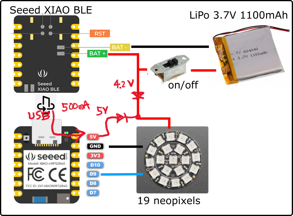
What is the allowable mA draw on the 3V pint? And, if it can’t handle 19 LEDs, then is there some way to power it directly from the LiPo battery instead? Like, running the power wire from the LiPo to both the V+ on the MCU and the V+ on the LEDs? (and ground to both the MCU ground and LED ground, and then a signal wire from the MCU to the LEDs)
No that should be fine. Running the LEDs using 3V is fine, I’ve done so before. (they get a little bit dimmer, but that is totally fine. In fact, I will be reducing the brightness anyway.)
Since the operating voltage of the MPU (3.3V) and the LEDs (4.2V to 3.7V) are different, is a level shifter required?
Even if the MPU outputs HIGH, the LED may not recognize it as HIGH.
If I understand it right, the LEDs will interpret the signal based on the supplied voltage being fed into the LED. So, if I supply 3V to the LEDs, then it will use that as the reference voltage, and so a 3V signal pin should be fine. I’ve done this in other projects where I’ve run these kind of neopixels using the 3V power pin and a digital out pin as the signal pin.
My current worry is how much power I can draw from the 3V power pin before overloading the Seeed regulator.
The LDO used for nRF52840 may be SGM2040 (I forget where I saw it).
According to the datasheet, the output current is 250mA, but I don’t think the output current is expected as an XIAO. The 3V3 pin is probably provided for the purpose of supplying small current to sensors, etc.
Seeed doesn’t publish these kinds of values, so the answer is that the XIAO can output until it gets hot?
The second option powers the LEDs directly from the LiPo battery. But, I’ve never seen this suggested before… and, I worry about what would happen when I plug in a USB to recharge the lipo battery. I presume the power flowing from the XIAO’s charging circuits would ‘flow into’ the LEDs? Is that bad? I don’t know…
The power supply circuit for the nRF52840 is shown below. Please refer to it.
When USB is connected, up to 4.2V is applied to the battery. The LEDs connected to the same terminals as the battery are also powered, but if this is a concern, why not disconnect the LEDs with a switch?
By the way, what is the required peak current in mA, which may vary depending on the pattern of light emission?
I could add another power switch for the charging… But I would like to know if this is required since… well, at some point, someone is going to forget to disconnect the LEDs before charging!
As for the draw, at maximum brightness white, it will draw 60mA*19, so 1140 mA. But it will be rare that all lihgts are on, and rare that they will be white. So… the answer is, it depends. Rough estimate is half the pixels are on, and probably each drawing 30 mA, so 300mA. I could add in code to guard against too high draw if required…
I have never checked to be sure, but I don’t think it will break.
Charging current is limited to 50mA, so if the LED is lit, it may not be possible to charge the battery.
Hi there,
SO in this post is an example for the Xiao nrf52840 the code in the zip file includes the indicator of weather the usb is plugged in or not.
HTH
GL PJ
Ah great! Thanks. I think I will try the P0_17 pin trick and do it in software. If the LEDs had a reference voltage of 5V, the 3V signal might not work anyway.