I am very new to wireless communication, i have purchased two Wio-E5 mini boards for doing point to point communication. I have downloaded the LoRaWan software, but i want only P2P communication, how do i modify the above code? I am from India what parameters can i use and do i need approval from any agencies?
I think the link below will be helpful.
Thank you very much for the reply. I have seen the first link but I am not familiar with Arduino but STM32, so can I get anything simple example using STM32?
I’ve only ever run it on Arduino. Sorry I couldn’t be of more help.
I will try to implement in Arduino and follow the link to program but i have few questions if you can help me. I have seen this in the program
// RM0461 Reference manual Rev 8 37.1.4 IEEE 64-bit unique device ID register (UID64)
#define MASTER_UID *((uint32_t*)0x1FFF7580) // use uid64 dor Master device UID
#define SLAVE_UID 0x05370378 // sample Slave device UID
How do i get them? How do i select my region? I have not registered in The Things Network, is it mandatory for P2P communication? Please advise.
If you’d like to use this as a reference, please use the STM32WL_P2P_Verify_1.zip file from Post #8.
An ID unique to each chip is stored at address 0x1FFF7580. This ID is used to identify the communication partner.
Executing Serial.println(*((uint32_t*)0x1FFF7580)); will display the chip’s ID. The master must know the slave’s ID in advance, and the slave must know the master’s ID in advance.
You will need to modify radio.begin(922.6, 125.0, 12, 5, 0x12, 13, 8, 1.7, 0); to match your region.
Note: Please pay attention to line 40 of the slave sketch. You will need to modify it depending on the Wio-E5 mini you are using.
You don’t need LoRaWAN for simple point-to-point communication. The Wio-E5 supports both LoRaWAN and raw LoRa (P2P) modes. For two boards talking directly, use the SubGHz_Phy P2P example instead of the LoRaWAN example. Seeed also provides examples and AT firmware that support P2P operation. Wio-E5 mini | Seeed Studio Wiki
I only saw LoRaWAN example from Seeed studio wiki but i have not seen code for P2P communication. Can you point me to that example.
Oh I am sorry. I though that Wio-E5 Mini has the same features of Wio-E5 LoRa. It looks ike Wio-E5 LoRa supports P2P but Mini does not. Grove - Wio-E5 LoRa P2P Example | Seeed Studio Wiki
I am not sure why do you say P2P is not supported in the Mini. Already @msfujino has shown the code using Arduino, are you saying the example is not available?
Sorry I did not see his answers when I typed my answer. Since, I could not find any example provided by seeedstudio, I assumed that P2P might not be possible with mini.
Hi there,
So, you got the best recommend from @msfujino , follow his lead and I would offer this link below also , you are NOT alone in India doing this, See here , LOL 

HTH
GL  PJ
PJ 
I downloaded the code but you are using EWARM, but i am using STM32 Cube Ide, i have never ported the code. Do you have STM32 Cube Ide only for P2P communication?
Hi there,
So , No I have not ported it myself, But I did ask our AI, LLM
Prompt: does such an example exists"
Answer:
Yes, such an example absolutely exists!
Because the Wio-E5 / LoRa-E5 mini uses the STM32WLE5JC micro-controller, it is fully compatible with STMicroelectronics’ official software ecosystem, STM32CubeIDE, and the STM32CubeWL Firmware MCU Package.
1. The Official ST Example: SubGHz_Phy_PingPong
ST provides a dedicated Point-to-Point (P2P) example project that compiles natively in STM32CubeIDE:
-
Location in ST Package:
STM32Cube_FW_WL_V1.x.x\Projects\NUCLEO-WL55JC\Applications\SubGHz_Phy\SubGHz_Phy_PingPong -
What it does: Two boards send alternating P2P LoRa packets (Ping → Pong) without needing a LoRaWAN gateway.
How to Port SubGHz_Phy_PingPong to Wio-E5 mini:
Since the example is pre-configured for the NUCLEO-WL55JC evaluation board, you only need to adjust the RF switch pin configuration in radio_board_if.c:
C
// Wio-E5 / LoRa-E5 RF Switch control pins:
// Receive mode:
HAL_GPIO_WritePin(GPIOA, GPIO_PIN_4, GPIO_PIN_SET);   // PA4 = 1
HAL_GPIO_WritePin(GPIOA, GPIO_PIN_5, GPIO_PIN_RESET); // PA5 = 0

// Transmit mode (High Power):
HAL_GPIO_WritePin(GPIOA, GPIO_PIN_4, GPIO_PIN_RESET); // PA4 = 0
HAL_GPIO_WritePin(GPIOA, GPIO_PIN_5, GPIO_PIN_SET);   // PA5 = 1
2. Ready-Made Community Repositories
If you don’t want to modify ST’s Nucleo example manually, there are pre-configured GitHub repositories specifically tailored for Wio-E5 / LoRa-E5 + STM32CubeIDE:
-
Seeed Studio’s Official STM32Cube Repository: Search GitHub for
Seeed-Studio/LoRa-E5-Node— this repository includes prepared sub-GHz radio and P2P code structured for STM32CubeIDE. -
RadioLib / Arduino Core for STM32: If the user in the thread wants a lighter API than ST’s HAL library, they can use RadioLib with the STM32 Arduino Core in STM32CubeIDE/VS Code to run simple P2P scripts across Wio-E5 mini hardwareYes, a native STM32CubeIDE example for P2P communication exists.
Because the Wio-E5 / LoRa-E5 module is based on ST’s STM32WLE5JC microcontroller, you don’t need to manually port EWARM projects. You can use the official ST point-to-point firmware:
-
STM32CubeWL
SubGHz_Phy_PingPongExample: ST’s official STM32CubeWL MCU Firmware Package includes a native STM32CubeIDE project calledSubGHz_Phy_PingPong. This application provides a full point-to-point (P2P) ping-pong RF transmission/reception demo. -
Seeed Studio STM32CubeWL Repository: Seeed Studio maintains a ported version of the STM32CubeWL firmware package on GitHub specifically configured for the LoRa-E5 pinouts and RF switch control (
PA4/PB5RF switch control pins).
How to get it in STM32CubeIDE:
-
Option 1 (Seeed Repository): Download or clone Seeed Studio’s LoRa-E5 STM32CubeWL Repository. Under
Projects/NUCLEO-WL55JC/Applications/SubGHz_Phy/SubGHz_Phy_PingPong/STM32CubeIDE, you will find ready-to-import STM32CubeIDE project files (.project/.cproject). -
Option 2 (STM32CubeMX Generator): Open STM32CubeMX, select the STM32WLE5JC target, enable the SubGHz_Phy middleware, select PingPong, and set the Toolchain/IDE target to STM32CubeIDE.

Way above my pay grade here, so Hope it’s useful.
HTH
GL PJ
Thank you very much.
I made the software ready with compilation in STM32 Cube Ide, but i am facing problems with flashing, below are the messages i get when flashing
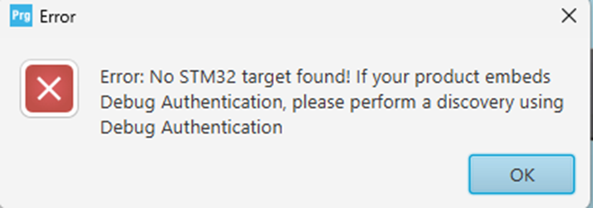

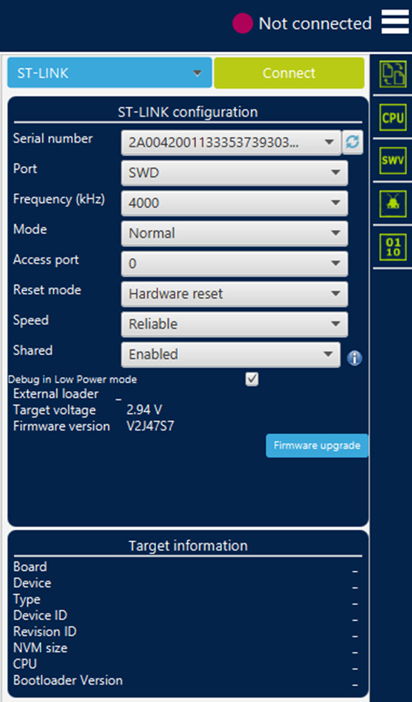
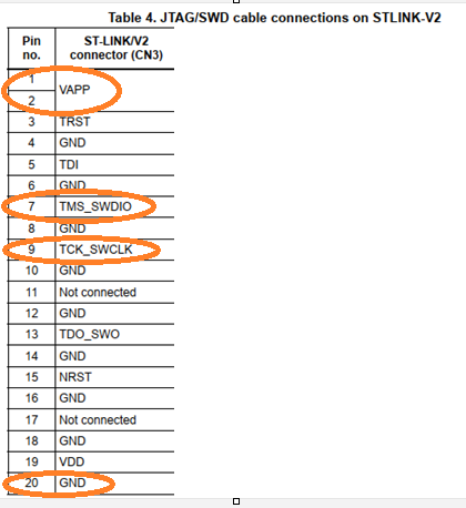
Hardware connections are DIO, CLK, Gnd are connected from debugger to the E5 device. How to resolve the issue, i am not connecting either 3.3V or 5V. Is it the problem?
Hi there,
So, you deserve a STAR  . You are almost there & I have seen this post before,(i.e.Flashing issues) Not real sure , you’ll need to search @msfujino , helped them figure it out as he has more experience with the Cube stuff AFAIK and hardware.
It may be you need the V_ref of 3.3v I’m not familiar enough with it. but it’s the same situ on Nrf DK’ dev boards with JLink for flashing. some require the V_ref voltage and some don’t depends on the configuration. reset or power on, there may be some required method.
Stay at it , maybe he will comment meanwhile.
HTH
GL PJ
Ok i will wait for @msfujino recommendation.
Hi there,
So I see, this from the LLM.
Yes it’s as I suspected, you need a V-REF
Looking at your ST-LINK logs, the key error is Target voltage: 0.00 V.
The SWD debugger’s V_REF pin doesn’t power the board—it only senses the target’s voltage so its internal level shifters know what voltage to use. Without power or a V_REF connection, the target STM32WLE5 chip is turned off.
To fix it:
-
Power the Wio-E5 mini via USB (or connect 3.3V from your programmer to the board’s 3.3V pin).
-
Connect the programmer’s
V_REF/VTGpin to the 3.3V pin on the Wio-E5 so the ST-LINK detects ~3.3V.
here is what I found…
To resolve this, they need to do one of the following:
-
Option A (Power over USB): Plug a USB cable into the Wio-E5 mini to power it independently, and connect the debugger’s
V_REFpin to a 3.3V pin on the Wio-E5 so the debugger senses the logic voltage. -
Option B (Power from Debugger): Connect the 3.3V power output pin from their debugger/programmer to the
3V3pin on the Wio-E5 (if their debugger supports supplying target power). -
Option C (SWD Pinout Check): Verify the 4-wire SWD setup:
-
SWDIO $\rightarrow$ SWDIO
-
SWCLK $\rightarrow$ SWCLK
-
GND $\rightarrow$ GND
-
V_REF / VTG $\rightarrow$ 3.3V (Target Power Sense)
-
You got this,
HTH
GL PJ