Hi there,
Yes,
On the standard 14-pin / 20-pin ST-LINK/V2 JTAG/SWD header, Pin 1 / Pin 2 (VAPP) is indeed the Target Voltage Reference / Sensing pin (V_REF / VTG).
For Option A (powering the Wio-E5 via USB), your proposed wiring is exactly right:
-
Pin 1 (VAPP) -----> 3.3V on the Wio-E5 (Senses ~3.3V so ST-LINK logic level shifters activate)
-
Pin 7 (TMS_SWDIO) ----->SWDIO
-
Pin 9 (TCK_SWCLK) -----> SWCLK
-
Pin 4/6/8 (GND) -----> GND
Once you connect VAPP to 3V3 while the board is plugged into USB, STM32CubeProgrammer will detect Target voltage: ~3.3V and should flash successfully.

HTH
GL  PJ
PJ 
It got connected thank you, loose contact on CLK i soldered now, sorry trying to do in hurry.
I flashed the hex file, i am trying to program again and to connect it is not happening. Is there a possibility i corrupted the board, RED led is glowing? Please advise.
Hi there,
OK, SO # 1 don’t panic, NO you can’t overwrite the bootloader. it’s permanent from factory.
Your code re-assigns the SWD & CLK pins often by default, so You need to connect UNDER_RESET from what I understand.
To use “Connect Under Reset”:
-
Hardware Reset Connection: Connect the NRST pin on the Wio-E5 mini to the NRST pin on his ST-LINK programmer (or physically hold down the RST button on the board).
-
STM32CubeProgrammer Settings:
-
Open STM32CubeProgrammer.
-
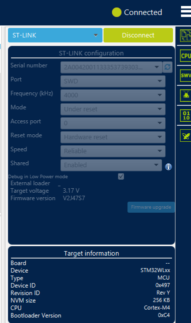
In the right-hand panel under Mode, change Normal to Under Reset.
-
Set Reset Mode to Hardware reset.
-
Connect & Full Chip Erase:
-
Click Connect (if holding the button manually, release the RST button right as you click Connect).
-
Once connected, perform a Full Chip Erase (Mass Erase) to wipe the hex file.
-
Boot0 Pin (Alternative): If hardware reset doesn’t work, pulling the BOOT0 pin HIGH (3.3V) during power-up forces the STM32WLE5 to boot directly into the factory ROM bootloader instead of executing his flashed hex code.
LLM’s take is 2 fold,
1. Re-purposed SWD Pins / Low-Power Sleep
When compiling custom firmware (especially sub-GHz/LoRa code using SUBGHZ_PHY), the new code often does one of two things immediately on boot:
-
Reconfigures SWD Pins: The hex file might reassign PA13 (SWDIO) or PA14 (SWCLK) as standard GPIOs or RF control lines.
-
Enters Stop/Standby Mode: Sleep modes disable the internal MCU clocks required for the SWD interface to respond to the programmer.
Once the MCU boots into that newly flashed code, the ST-LINK loses the ability to attach to the CPU core dynamically, throwing a connection error even though power and physical wiring are fine.
2. Overwriting the Bootloader
If he flashed the hex file starting at base address 0x08000000 without preserving factory system memory boot logic or dual-bank offsets, he replaced whatever factory firmware was running. However, on STM32 architecture (including the STM32WLE5 inside the Wio-E5), the official system bootloader is burnt into read-only System Memory, so it cannot be permanently erased.
I haven’t performed this tech myself personally , However it was one of the forums suggestions in the past.
HTH
GL PJ
Have you ever used CubeProgrammer to flash and run code on a Wio E5 mini or other ST32 chips before? If this is your first time, please practice with a simple code that makes an LED blink.
I have a question to better understand your current situation.
I flashed the hex file,
What kind of code did you flash?
I’m trying to program it again, but I can’t get it to connect.
Are you unable to flash the new code? Or are you unable to connect? Or is the code you flashed not working?
The red LED is glowing.
Since the red LED is connected to the port, it’s lighting up as specified in the code you flashed.
Translated with DeepL.com (free version)
Thank you for the support. I have experience in STM32 debugging i figured out that
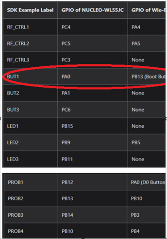
In the STM32 Nucleo board source code they configured the BUT1, but it is Boot pin in this board. I commented that portion of the code in the gpio.c file. I am now able to flash and debug, but now i am facing one other reset issue
void MX_SubGHz_Phy_Process(void)
{
  /* USER CODE BEGIN MX_SubGHz_Phy_Process_1 */

  /* USER CODE END MX_SubGHz_Phy_Process_1 */
  UTIL_SEQ_Run(UTIL_SEQ_DEFAULT);
  /* USER CODE BEGIN MX_SubGHz_Phy_Process_2 */

  /* USER CODE END MX_SubGHz_Phy_Process_2 */
}
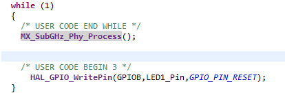
I don’t have much idea on the UTIL_SEQ_Run, I need to either debug that code or replace with some simpler code for transmit and receive. I feel the code from @PJ_Glasso i can use, but not yet decided.
Finally i used the ported STM32 cube software, the code modifications are when ever a message is received the LED will blink. I have attached the video, few things can you please help to clarify, i can’t run the code in debugging mode, is it correct? One node always stays in Master mode. The source file which i edited for toggling is attached. Thank you in advance for your time and help.
subghz_phy_app.zip (3.8 KB)
Video.zip (1.9 MB)
Hi there,
I am in Awe 
 of you
  SIR
SIR

way to stay at it and get it going, the connect under reset, should help even on the Nordic stuff sometimes it’s required.

To answer your question about why it won’t run in debugging mode: it’s actually by design in that STM32 Cube software, but you can fix it easily!
The UTIL_SEQ_Run function you highlighted acts as the main background loop. When there are no tasks pending, it automatically drops the MCU into a low-power sleep mode to save battery. When the core sleeps, it shuts off the internal clocks feeding the SWD 
 debug pins, which instantly drops your debugger connection.
How to fix it: You just need to tell the MCU to keep the debug clocks alive while the core sleeps. Try adding these lines in your main.c right before your main loop or before calling MX_SubGHz_Phy_Process():
HAL_DBGMCU_EnableDBGStopMode();
HAL_DBGMCU_EnableDBGSleepMode();
The LLM also ADD’s;
(Alternatively, check your sys_conf.h or subghz_phy_app.h file—there is usually a macro like #define LOW_POWER_DISABLE 1 you can uncomment).
Toss that in, and your debugger should stay perfectly connected the whole time. Awesome work getting the port and the LED toggle running! Sounds simple to lurkers but that is a milestone when you jump in cold.
HTH
GL PJ
Thank you for your kind words. I can say with your and @msfujino support i had the confidence i can get through as the terminology and everything is so new in wireless. I will try the one you suggessted for the low power mode and verify the debugger connection. Thank you once again for your support and time.