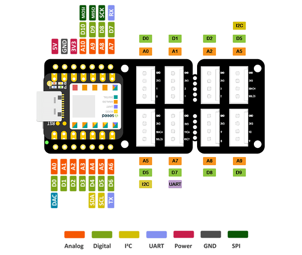
I have a question. I think I’ve figured out the answer, but I know next to nothing about electronics and wanted to check with someone here who surely does. Now, this is an image of a “shield” they call it that I have for a Xiao ESP32C3.
In this image it shows 8 connectors, which have 4 interface types, you have digital–that means the values will be 0 or 1. You have analog which means the values will be a range. You have two that support some sort of protocol UART and I2C.
Please correct me if I got this wrong.
Which brings me to the part I am unsure about, sensors and code.
Now if I have a sensor like a LED, I can plug this into a digital or an analog port? Its a question? Yes, but should a port be solely a I2C or a UART it would make no sense.
Assuming I am on the right track, I need to tell the system not only have I plugged in an LED, but it needs to supply power to it, so in software that looks like this in Arduino speak.
Setup() {
    pinmode(D0,OUTPUT) or maybe pinmode(D0,POWER)?
}
So the basic syntax is the command “pinMode” with the parameters in this case telling it to send power to D0 on the assumption I just want to turn the LED ON or OFF. Would send power to A0 if I wanted to be able to vary the power supplied, to get a brighter or dimmer LED?
Over to management of said LED. Now the piece of code I made up reads the current value of the line D0 and depending on it toggles it to HIGH or LOW with the commands digitalRead and digitalWrite. Commands I assume are linked with the physical control line to the D0 register.
void loop() {
buttonState = digitalRead(D0);
if(buttonState == LOW) {
digitalWrite(D0, HIGH);
}
else {
digitalWrite(D0,LOW);
}
In summary I used different commands on the same register, that in effect map to different bits of hardware
Does all this make sense? Does anybody know of a good book I can get that will help me put the different pieces together like this. In the big scheme of things this isn’t rocket science, if you understand the basics it all makes sense.
