Grazie, Marco!
When the source codes of the latest APP v2.52 / SYS v1.51 will be released to the SeeedStudio GIT repository ?
marcosin thank you! with your program DSO much more usable.
And thanks for the source code, it is very helpful in understanding the structure of the program
ps. and, I think this mod deserves a separate topic )
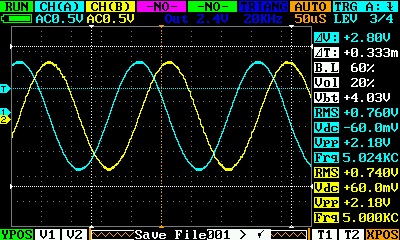
FPGA261 is much more stable with triggers
Thank you so much marcosin for improving the quad!
I have been pulling my hair out trying to understand the structure of the menu. You work has made it easier to understand.
Tony
Hello Chip, the community expects more and your sources. Why, in an open-source project, you do so much good work and then you’re jealous of it?
Now there marcosin, which is improving but much work must start from the original sources and not from yours.
So we users must choose whether to use your version or the version of marcosin.
Does it seem a normal thing?
Thank’s
The menù structure is the same of original firmware but i’ve added new function for the top buttons:
Button 2 (square)
-Push and release : change trigger automatic level
-Push and hold : enter in calibration
Button 3 (dot)
-Push and release : view or hide the lateral meters menù
-Push and hold : save settings
Button 4 (triangle)
-Push and release : change the meter menù viewing combination
-Push and hold : change full buffer or single frame buffer
As regards the question open-source, I agree with what users say, if all we’ll divulge our work would have an excellent result!
It will seem strange, but both are not correct!
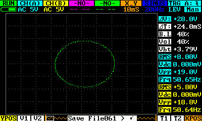
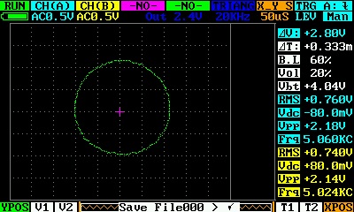
In my firmware not get a circle, because I kept the grid as a real voltage reference.
In fact if you look on the grid the amplitude of the signals is correct.
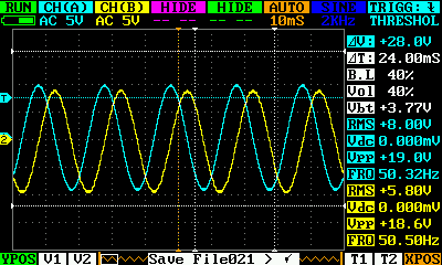
Track A is almost 4 squares (x axis), track B (y axis) a little less.
The problem of the deformation is due to the size of the grill is 30 pixels horizontally and 25 vertically.
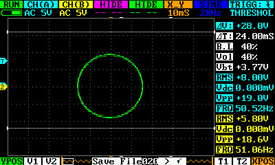
In chip firmware the shape is correct but the references voltage grid for the x axis is incorrect.
Sin and cos must give circle for correct visual perception.
For mode x_y grid must be alike on x and y.
It would be good so to make.
Try this
DSO_Sm_V1.8.rar (75.5 KB)
Thank you. At monday shall try with generator.
I’ve just updated the firmware to system 1.51 and app 2.52, along with the required FPGA. How is it different from the previous version? I can’t see any difference. Also, is there any plan to fix the issue of extremely slow screen updates at 5ms/div and slower sweep rates? I realize the update rate is very slow because the scope collects 12 screenfuls of data for every one you actually view, but it makes it impossible to view audio signals in real time. It would be great to have an option to collect only one screenful when you want to, or to have that automatically kick in at slower sweep rates. That update problem is the biggest flaw in the DSO Quad.
see single screen mode in marcosin fw
marcosin, thank you very much for your great work. However, there is few bugs, which make DSO somewhat unusable for me.
-
Scrolling often does not work in normal and single mode (background scrolls, but waveform does not). At 2ms/div and higher it never works for me, at lower than 2ms/div it works sometimes.
-
In single screen mode in norm mode it should hold last triggered (useful) waveform. Instead, it continues to refresh few more times and of course erases waveform of interest by useless data. If I manage to press pause (HOLD) before useful waveform disappears, and then press continue (RUN), waveform of interest stays on the screen permanently, as it should (until next useful waveform of course).
-
In norm single screen mode it loses large portions of the signal. This is especially noticeable at 100ms-1s/div. It draws waveform from left to right, then stops for few seconds (during these seconds data is lost, trigger level is ignored). After that it usually draws waveform from left to right few more times, erasing any useful data (see #2). Scan mode (single screen) is not affected by this bug and works perfectly. So this bug is specific to norm mode.
-
In norm single screen mode at 100ms-1s/div it often lose or misplace (relatively to trigger XPOS) waveform of interest.
marcosin, you did very great work! However, some bugs are left, so I want to help by trying to fix them myself (if you are going to fix some/all of them in near future yourself let me know in order to prevent duplicate work).
I would very appreciate your advice on the following problem. Currently what stops me from trying to debug or fix the code myself is the fact that in source code you last posted, there is no Makefile or anything else except source/header files, can you please give me advice how to proceed? Obviously you can’t build it without Makefile or some script(s), so I’m guessing you forgot to put some files in the archives (or am I missing something?). By the way, if you post the source for the latest version of your firmware, I would appreciate it very much.
P.S. Of course if I fix or improve anything I promise to post patch(es) for the source code.
In github You can find all the needed files to compile the project.
You can download the APP2.51 project and replace the source and include folders…
Source_Sm_V1.8.rar (69.9 KB)
Marcosin, thank you very much. Now mode X_Y seems normal.
Yes, I can to confirm it. I successfuly work with Marco’s sources under IAR, using the official projects as template.
BTW, I successfuly realized debug via ST-Link. Till now only SYS area.
Marcosin et al - Great Work!!
Is there any text description of how the source is organised to help beginners improve the code? I have the toolset working and I’m sure I could improve the code if I knew where to start. Unfortunately, I do not have time to analyse it myself.
Thanks
Dave
