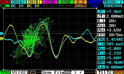
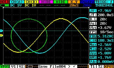
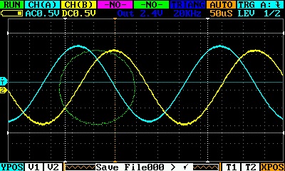
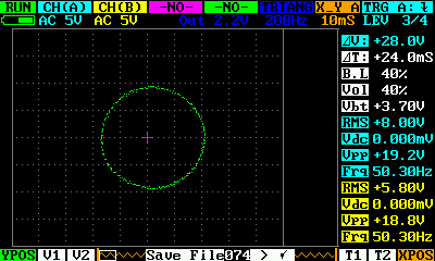
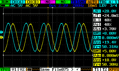
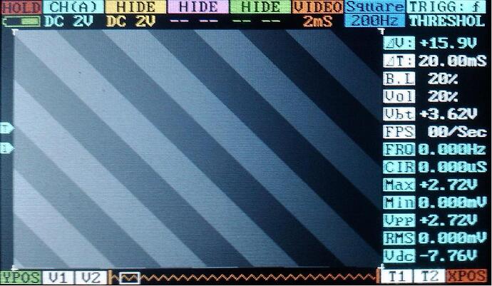
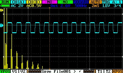
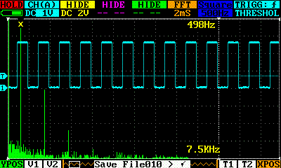
More pictures from the sinus and the music
Thank You!
The circle is a bit on the right, I’m working to fix it, it’s a offset track problem…
Can someone enlighten me a bit?
These are the current efforts:
- Chip’s closed source modifications
- gabonator’s new interface:
github.com/gabonator/DS203
viewtopic.php?f=10&t=2362&start=20 - marcosin’s new firmware (this thread)
Is marcosin’s new firmware based on gabonator’s effort?
Is it the same?
Would be really nice, if seedstudio could release the latest sourcecode,
gabonator rebase his source on the new release, and marcosin’s code and
gabonator’s code could be merged.
Best,
Laszlo
The Marcosin firmware is a wonderful improvement. Thank you! The single frame buffer mode makes the Quad useful for audio-rate signals at last. I see one bug in it, though: when I switch from full buffer to single frame, the VDC reading goes (with no signal input) from 0.000mv to -1.60v.
Has anyone had success with the hardware mod for increased bandwidth? Or know where to get the required small-value caps?
Oh, also, I wanted to try gabonator’s interface, but I could not find a downloadable file that would install on my Quad. I read about the web vs binary file. and I got the binary. But it showed .err when I tried to install it, and it wouldn’t run.
One more question: What is the difference between X-Y A mode and X-Y S mode?
Thanks.
Hey,
Gabonator’s work is here:
viewtopic.php?f=10&t=2362&start=20
And here:
github.com/gabonator/DS203
The github also does contain a little README.
Best,
Laszlo
X_Y S is in SCAN mode, untriggered
X_Y A is in AUTO mode with trigger active, it’s not complete, it don’t display the trigger position on the figure.
I’m working to FFT now, I will complete the X_Y as soon possible…
Thanks! That helps. I have two suggestions for future revisions:
- Fix the incorrect voltage reading when using single-frame mode.
- In single-frame mode, allow shifting the trigger position to the left side of the screen. Perhaps that might require writing 1.3 screens or so into the buffer instead of just 1, but that shouldn’t affect the update speed noticeably.
Thanks again.
Michael
Good work!
Why You don’t share your code?
I’m doing it, but i’m not a good developer!
I do not share my source because I think it is not correct, if the manufacturer DSO will use them to increase their sales.
Sorry for my english.
I do not think the same thing, because I think it is convenient to the manufacturer that it remain open source.
This DSO has many other defects that can not be eliminated with only the firmware, it is always a means little more than a game.
it can never be a professional tool and therefore expensive, but it is an interesting tool, certainly
But everyone thinks as he wishes, I respect all! 
This device has limitations in frequency analog circuits. Errors are not corrected, I did not notice
Any device has limitations. 2MHz bandwidth is already good for a pocket-sized oscilloscope.
Plus, the open source code - do whatever you want.
What does that do?
