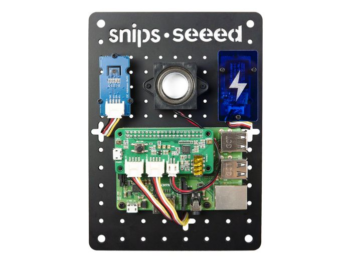
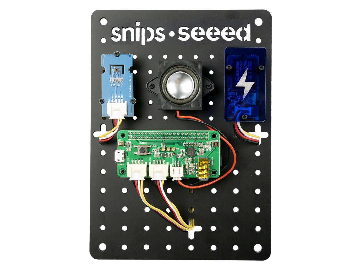
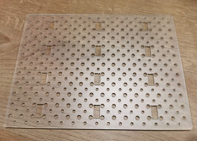
The idea would be a base plate with screw holes, and corresponding standoffs, nuts and bolts to attach the Grove devices, and other boards like the Wio Terminal as well.
Screw holes ø ≃2.14mm.
Square matrix of screw holes distanced by ≃1cm to fit the 2x2cm and 4x2cm Grove devices
Elongated holes for non-standard boards like the Wio Terminal.
That’s indeed a good suggestion. We would love to provide with more more interesting and useful accessories for our products.
Develop such a plate and have it sold on Bazaar is a big task indeed. One concern of mine is that a large number of users are maker, and it would not be so difficult for them to design one plate or laser cut one with the design file. Therefore I wonder how much would it be in your place to laser cut a plate like this? Do you think it would be more convenient and logistics cost saving that we provide with the design file and users have it laser cut in the local?
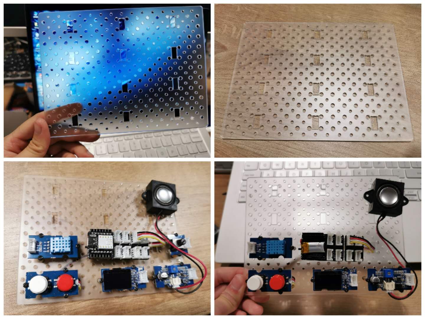
According to your suggestion, I’ve tried to design a plate like this. As most of the main boards have M3 assembling holes, this plate has both M2 & M3 holes and also space for Grove Cable connectors to go through.
The plate is with M2 and M3 holes on regular 10mm hole distance respectively.
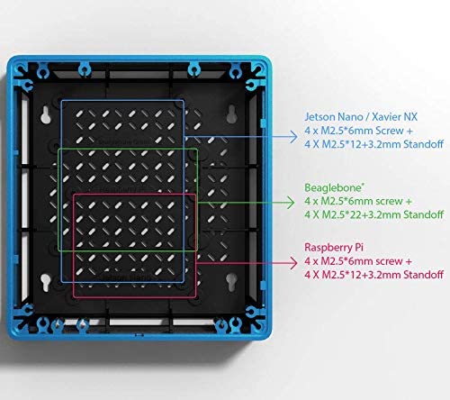
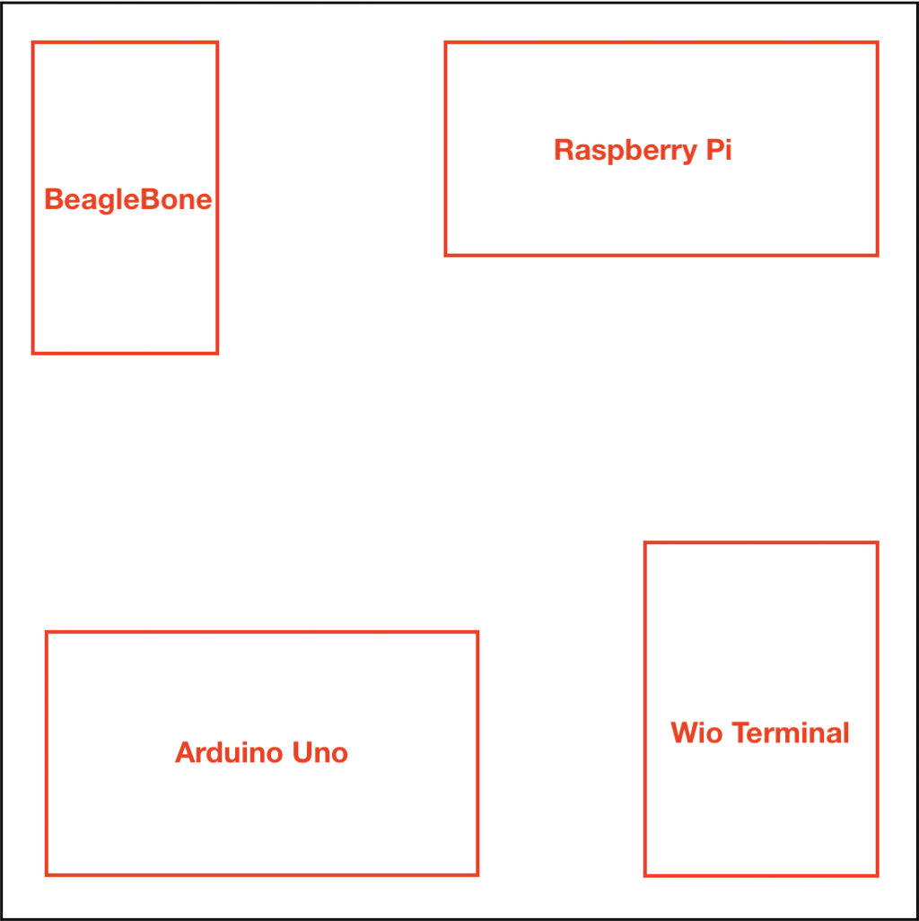
I would like to make the hole to host different types of main boards but found it difficult, since each board has different hole distance standard, which could not fit the regular holes, and it is also hard to decide for users which position to assemble the main board.
I am considering maybe making a convert plate for the main stream main board. What would you suggest?
Regular hole distance may looks better?
I know it is hard to design a one-for-all plate as each board has different hole sizes and placement. On top of that, most boards are based on the imperial system (ie.inches) while the Grove system relies on the metric system (ie.cm).
Here are some ideas:
Feature Xs on the plate for easy adjustment to the boards, like in the re_computer case.
Metric and Imperial are a pain when used alone, when used in combination they become deadly as well as one standard polluting the other. General Motors introduced Metric and immediately introduced high tensile metric bolts for engines!
I design military and industrial equipment and using 2mm screws are a BIG mistake because of handling challenges, and the poor support they offer due to their small head sizes. We run vibration tests on our products and have experience in the choice of fastenings.
Three millimetre and 4mm would offer strength. There are so many holes
An acrylic panel of that size will also require support in the centre.
The pictures and drawings are not clear enough to determine whether the Acrylic ís molded or machined (drilled or punched) - the latter stressing the material.
Obviously, these Base Plates are not suitable for anything other than prototyping.
Ming suggested offering design files. Ì so, the option could be allowed to choose which holes should be drilled and which should be skipped.
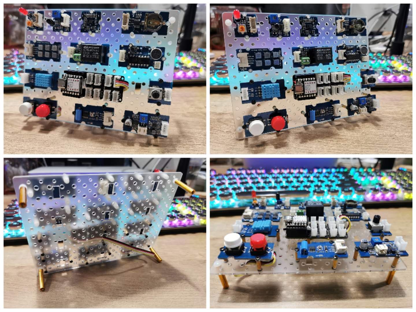
This acrylic plate is made by laser cutting, and could choose the thicker plate like 3mm/5mm to make it stronger. For Grove modules and main board, it will give well supports, for display and prototype purposes.
Here I attach my draft design Grove Plate CAD Design .dxf file
for you, in case you would like to modify it to fit your specific purpose.