Hi there,
So Before you even think about using a battery, Don’t be pound wise and Penny foolish. Start with a GOOD Battery. Use a PMIC or Voltage divider if that is all you have.
Good-quality LiPo batteries, like what I use is the 3.85V 450mAh cell, usually include built-in protection circuits. These Protection Circuit Modules (PCMs) or Protection ICs prevent:
- Over-discharge (deep discharge) – Cuts off power before voltage drops too low.
- Overcharge protection – Prevents charging past the safe limit (typically ~4.35V for 3.85V cells).
- Overcurrent & Short Circuit Protection – Prevents excessive current draw or shorts.
 How to Check If Your Battery Has Protection
 Look for a Small PCB Attached to the Battery
- Most protected LiPo cells have a small circuit board near the terminals.
- If it’s a bare cell without a PCB, it may NOT have protection.
 Check the Datasheet or Manufacturer Specs
- If the spec sheet mentions “PCM,” “BMS,” or “Protection Circuit”, then it includes built-in safety.
 Test Voltage Cutoff Behavior
- If you discharge the battery below ~3.0V and it cuts off, it has protection.
- If it drops below 2.8V and still works, it might be unprotected.
 What If the Battery is Unprotected?
- If no protection is built-in, your Xiao must handle over-discharge cutoff.
- The Xiao nRF52840 includes a fuel gauge and voltage monitoring, so you can program a low-voltage cutoff (e.g., shut down at 3.0V).
- If you charge externally, use a LiPo charger with built-in protection.
The tiny PCB with two chips on top of the 3.85V 450mAh LiPo battery is the Protection Circuit Module (PCM). That confirms the battery has built-in overcharge, over-discharge, and short-circuit protection! 
What the Tiny Chips Do:
- Battery Protection IC – Manages voltage levels and prevents overcharge/discharge.
- MOSFETs – Act as switches to disconnect power if unsafe conditions occur.
 How the Protection Works
 Overcharge Protection → Cuts off charging if voltage goes above 4.35V.
Over-discharge Protection → Cuts off load if voltage drops below ~3.0V (typically 2.8V-3.0V).
Short Circuit/Overcurrent Protection → Shuts off if too much current is drawn.
 What This Means for Your Xiao Setup
You don’t need to manually monitor voltage in software.
The battery will shut off before deep discharge damage occurs.
Safe to charge directly using a proper LiPo charger.
Even with protection, you can:
- Monitor battery voltage via ADC (for display or logging).
- Set a software cutoff at ~3.2V to extend battery lifespan.
- Use a fuel gauge IC (like MAX17048) for more accurate charge monitoring.
I’m waiting for the Xiao to get a fuel gauge ic.. 

How the Xiao’s Battery Charger Chip Works with Your Protected LiPo
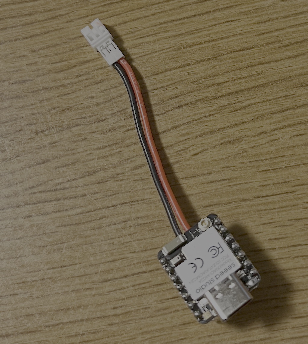
The Seeed Studio Xiao nRF52840 (and similar Xiao boards) include an onboard LiPo charging circuit, which works together with your battery’s built-in protection to safely manage charging.
How It Works:
Xiao Provides a Safe Charging Voltage
- The Xiao’s charger limits the charge voltage to 4.2V or 4.35V, depending on the model.
- Your 3.85V LiPo reaches 4.35V at full charge, so check if the charger matches.
Battery Protection Circuit Prevents Overcharge
- Your LiPo battery’s built-in PCM will disconnect the battery if the charger tries to overcharge.
- This prevents damage even if the Xiao’s charger malfunctions.
Battery Disconnects If Voltage is Too Low
- If the battery voltage drops too low (~2.8V-3.0V), the PCM cuts off output.
- The Xiao won’t see the battery until it’s charged back above the protection threshold.
 Charger Handles Safe Current Flow
- The Xiao’s charging chip limits current (typically 100mA to 500mA).
- This prevents overheating and ensures the battery charges at a safe rate.
 What You Need to Check:
Check Your Xiao’s Charge Voltage
- Xiao nRF52840: 4.2V charger
- Xiao ESP32C3/C6/S3: 4.2V charger
- Some models (not Xiao) can go up to 4.35V
- If the charger is 4.2V, your 3.85V battery won’t fully charge (stops at ~85% capacity).
Charging Current (mA)
- If the charger provides 500mA, your 450mAh battery takes ~1 hour to charge.
USB Power vs. Battery Use
- When USB is plugged in, the Xiao runs on USB and charges the battery.
- When USB is unplugged, it automatically switches to battery power.
 Final Thoughts
 Your battery’s built-in protection ensures safe operation.
The Xiao’s charging chip properly manages charge voltage & current.
If the Xiao charges to 4.2V max, your 3.85V LiPo won’t reach 100% (but still works fine).
No external charge controller is needed—Xiao and the battery PCM handle it!
HTH
GL  PJ
PJ 
(note) this includes text and formatting from AI agent…