XIAO nrfr52840 Changing Serial port pins

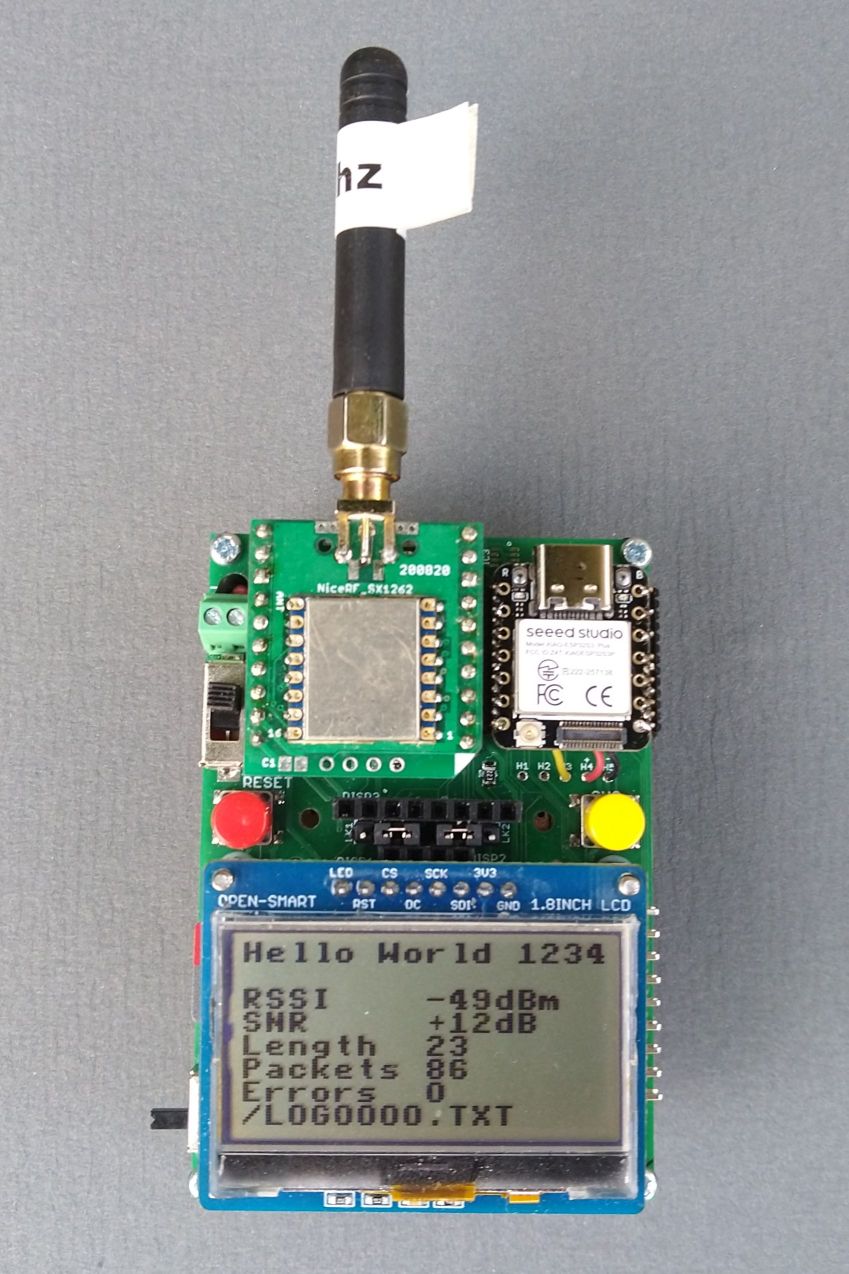
I have been building a small portable LoRa packet receiver and SD card logger with an LCD display.

Its based on the XIAO nrf52840 plus and the LoRa, SD card logger and LCD display are working. The LCD is very visible outdoors, even in strong sunlight. Its Powered for portable use with two 14500 Lithium cells on the back.

So far so good, the basics are working.

However a receiver that has fixed LoRa settings, Frequency, Spreading Factor, Bandwidth and Code Rate etc is not so useful. To change the LoRa settings the board normally needs to be re-programmed. I get around this by using a series of serial menus in the program so that the LoRa settings can be changed via a PC serial terminal application. The changed settings can be saved in a FRAM store so that they become permanent. So no need to re-program the board.

When out and about its not that practical to plug into a PC or Laptop, so I wanted a way to use a Bluetooth Serial Terminal on an Android phone to do the changes.

Connecting a HC06 to the D6, D7 serial port (Serial1 ?) is easy enough and it does work.

My problem is that I want to be able to use a switch to change the serial port used by the menus, i.e. choose between the USB serial connection or the HC06 Bluetooth connection.

I have simplified the code to that below. When the unit is reset or powered it reads the switch and attempts to redirect mySerial to the D6 and D7 pins. It does not work.

Any ideas how it can be made to work ?

Sample program below. The full program has all the Serial.print() functions set to mySerial.print();

#include <Adafruit_TinyUSB.h>
#define mySerial Serial

#define REDLED 11    //P0.26
#define BLUELED 12   //P0.06
#define GREENLED 13  //P0.30

#define LEDON LOW
#define LEDOFF HIGH
#define SWITCH1 D0  //P0.02

#define RXPIN D7  //P1.12
#define TXPIN D6  //P1.11

uint16_t seconds;

void loop() {
  mySerial.print(seconds);
  mySerial.println(F(" - Red Flash"));
  seconds++;
  digitalWrite(REDLED, LEDON);
  delay(100);
  digitalWrite(REDLED, LEDOFF);
  delay(890);
}

void led_Flash(uint16_t flashes, uint16_t delaymS) {
  uint16_t index;

  for (index = 1; index <= flashes; index++) {
    digitalWrite(REDLED, LEDON);
    delay(delaymS);
    digitalWrite(REDLED, LEDOFF);
    delay(delaymS);
  }
}

void setup() {
  pinMode(SWITCH1, INPUT_PULLUP);

  pinMode(REDLED, OUTPUT);
  digitalWrite(REDLED, LEDON);
  led_Flash(4, 250);

  if (digitalRead(SWITCH1)) {
    mySerial.begin(115200);
    digitalWrite(GREENLED, LEDON);
    mySerial.print(F("USB UART selected"));
  } else {
    mySerial.setPins(RXPIN, TXPIN);
    mySerial.begin(9600);
    digitalWrite(BLUELED, LEDON);
    mySerial.print(F("Bluetooth selected"));
  }

  delay(2000);
  digitalWrite(GREENLED, LEDOFF);
  digitalWrite(BLUELED, LEDOFF);

  mySerial.println();
  mySerial.println(__FILE__);
}

Hi there,

Hope all is Well, Easy one here… :grin: :+1:

. Serial vs. Serial1 Core Architecture

  • Serial is defined as the USB CDC interface (virtual serial over USB-C). It is not tied to physical UART GPIO pins, which is why calling .setPins() on Serial fails or does nothing.

  • Serial1 is the dedicated Hardware UART instance tied to the physical RX/TX header pins (D6 = TX, D7 = RX).

Because Serial (USB) and Serial1 (Hardware UART) are two completely different object classes in the Adafruit/Seeed nRF52 BSP, #define mySerial Serial locks mySerial into referencing only the USB interface at compile time.

Try this one :wink: :crossed_fingers:

-How to Fix It

To switch dynamically between USB Serial and Hardware Serial (HC-06 on D6/D7) based on a pin reading, you should use a Stream pointer (Stream* mySerial) instead of a macro definition. Stream is the base class for both Serial (USB) and HardwareSPI / Uart (Serial1).

Fixed Code Structure:

#include <Adafruit_TinyUSB.h>

#define REDLED 11    // P0.26
#define BLUELED 12   // P0.06
#define GREENLED 13  // P0.30

#define LEDON LOW
#define LEDOFF HIGH
#define SWITCH1 D0   // P0.02

// Use a Stream pointer so it can point to either Serial or Serial1
Stream* mySerial = nullptr;

uint16_t seconds;

void setup() {
  pinMode(SWITCH1, INPUT_PULLUP);
  pinMode(REDLED, OUTPUT);
  pinMode(BLUELED, OUTPUT);
  pinMode(GREENLED, OUTPUT);

  // Read switch state at startup
  if (digitalRead(SWITCH1)) {
    // USB Serial selected
    Serial.begin(115200);
    mySerial = &Serial;
    digitalWrite(GREENLED, LEDON);
  } else {
    // Bluetooth Hardware UART selected (D6/TX, D7/RX are assigned by default to Serial1)
    Serial1.begin(9600);
    mySerial = &Serial1;
    digitalWrite(BLUELED, LEDON);
  }

  delay(2000);
  digitalWrite(GREENLED, LEDOFF);
  digitalWrite(BLUELED, LEDOFF);

  if (mySerial) {
    mySerial->println(F("Serial initialized"));
    mySerial->println(__FILE__);
  }
}

void loop() {
  if (mySerial) {
    mySerial->print(seconds);
    mySerial->println(F(" - Red Flash"));
  }
  
  seconds++;
  digitalWrite(REDLED, LEDON);
  delay(100);
  digitalWrite(REDLED, LEDOFF);
  delay(890);
}

Key Differences:

  1. Pointer Usage: mySerial->print() replaces mySerial.print().

  2. Default Pins: Serial1 on the XIAO nRF52840 defaults to D6 (TX / P1.11) and D7 (RX / P1.12) out of the box, so no .setPins() remapping is necessary.

HTH
GL :slight_smile: PJ :v:

I see an Xiao esp32S3 in the pic ?

Thanks for the comment.

You did see an ESP32S3 plus in the pic, the PCB can take both. I was comparing the receive current of nrf52840 versus ESP32S3, there were only minor differences in the programs.

The results of that test were;

Receive current for nrf52840 plus with LoRa, SD card and display plus, 15mA

Receive current for ESP32S3 plus with LoRa, SD card and display plus, 84mA

You get the same issue with the ESP32S3, the Serial port is the USB also so you cant re-direct the pins as for a standard serial port.

The very high current consumption of the ESP32S3 is not good for a portable device really.

I was aware on the stream pointer approach, I recently modified my own LoRa library to use the arrow pointer so that the Serial.prints() in the library could be re-directed.

If the stream pointer approach is the only possibility I guess I might have to go that way.

Another question …

If the nrf52840 BLE UART code is used, the one that uses <bluefruit.h> that defines the ‘Serial’ as;

BLEUart bleuart; // uart over ble

So would that work with the stream pointer re-direct ?

Using a HC06 is not a major issue, there is a pin header to fix one to the back of the PCB, but if its not needed why fit it.

Dude , you always ask Good questions :grin:
I don’t know for sure, however The Nordic LBS demo is close to it,
The OTA , DFU is Steller too.

So , checked because it peaked my interest too.
Turns out , Yes, :+1: absolutely! BLEUart inherits directly from Arduino’s Stream class, so mySerial = &bleuart; works out of the box with the Stream* pointer redirect.

Stick with it—there’s a small learning curve when shifting away from standard AVR/ESP serial paradigms on these nRF52 chips, but the technical payoff in low-power efficiency and flexibility is huge.

If you want an easier way to get started and test BLE UART without hardware extra headers:

  1. Use BLEUart directly as your Stream target: Since it inherits from Stream, you don’t need the physical HC-06 module at all. You can assign mySerial = &bleuart; after calling bleuart.begin() and use the standard Nordic nRF Connect app or Adafruit Bluefruit LE app on your phone to read the output.

  2. Fallback to Serial when plugged into USB: Point mySerial = &Serial when USB is connected, and mySerial = &bleuart when running on battery. That gives you zero-extra-hardware wireless debugging with the exact same mySerial->print() statements across your whole sketch! :backhand_index_pointing_left: :grinning_face:

Low tech solush" to a High tech Problem. :wink:

HTH
GL :slight_smile: PJ :v:

I got the LED blink example and the full LoRa receiver program working with the nrf52840 BLEUart code, so success. Works on the ESP32S3 plus with HC06 too.

Thanks for the help.

Still using the switch on reset\power up to select USB or Bluetooth.

I found an example that programmatically detects if the ESP32S3 USB is connected;

https://forum.seeedstudio.com/t/xiao-esp32-s3-detect-usb-power-with-code/272220

But it won’t compile, the error is;

“Compilation error: ‘class ESPUSB’ has no member named ‘vbusPresent’”

Not sure how to detect if the USB is connected on the nrf52840.

Hi there,

Awesome… :+1:
Glad you got it going, on the Nrf52840 sense , there is a way to tell if the USB is plugged in,

1. XIAO nRF52840 (Adafruit / Nordic BSP)

Because the nRF52840 features a hardware VBUS regulator/detector, you can directly inspect the Nordic SoftDevice register to check for 5V presence (wall adapter, power bank, or PC host):

  • Direct Register Check:
bool isUsbPluggedIn = (NRF_POWER->USBREGSTATUS & POWER_USBREGSTATUS_VBUSDETECT_Msk);
  • Charging Pin (P0.17 / Pin 23):
bool isCharging = (digitalRead(23) == LOW); // Active LOW from onboard BQ25101

2. XIAO ESP32-S3 (ESP32 Board Package)

The ESP32-S3 uses an internal USB_SERIAL_JTAG PHY. To read raw 5V USB power presence without needing a data host:

  • Direct PHY Hardware Check:
#include "hal/usb_serial_jtag_ll.h"

bool isUsbPluggedIn = usb_serial_jtag_ll_phy_is_pad_valid();
  • Data Host Connection Check (CDC Serial):

This is the same patch for the ESP32S3 Xiao

#include "hal/usb_serial_jtag_ll.h"

// Check for 5V USB presence on ESP32-S3
String getUsbStatusESP32S3() {
  bool usbPower = usb_serial_jtag_ll_phy_is_pad_valid();
  
  if (usbPower) {
    if (Serial) {
      return "USB In - Data Host Connected";
    } else {
      return "USB In - Power Only (Charger)";
    }
  } else {
    return "USB Unplugged (Battery)";
  }
}

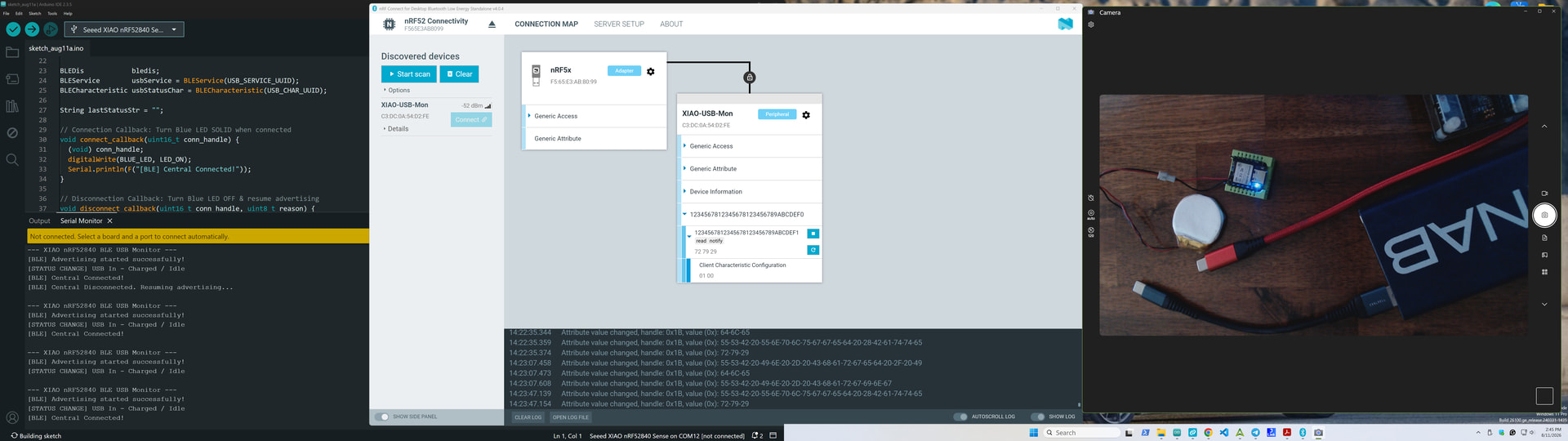
Here is the code I tested it with , keeps the BLE connection, You can plug & unplug USB or Power bank and get the status over BLE.. :+1: connected , charging, idle, disconnected from it. :wink:

/*
  =============================================================================
  Project:      XIAO nRF52840 BLE USB & Battery Power Monitor
  Target HW:    Seeed Studio XIAO nRF52840 / XIAO nRF52840 Sense
  BSP / Core:   Seeed nRF52 mbed-enabled core / Adafruit nRF52 BSP
  Framework:    Arduino / Adafruit Bluefruit nRF52 Library
  
  Description:
    Monitors 5V VBUS state via direct nRF52840 hardware power registers 
    (POWER_USBREGSTATUS) and battery charging status via the onboard BQ25101 
    charge pin. Transmits real-time status updates over BLE via Custom UUID 
    characteristic notifications.

  Onboard Hardware Mapping:
    - LED_BLUE : Pin 12 (P0.06) - Active LOW (Blink = Adv, Solid = Connected)
    - PIN_CHG  : Pin 23 (P0.17) - Active LOW (Low = Charging, High = Idle/Battery)
    - VBUS     : Direct HW Register (NRF_POWER->USBREGSTATUS)

  BLE Configuration:
    - Device Name : XIAO-USB-Mon
    - Service     : Custom 128-bit [F0DEBC9A-7856-3412-7856-341278563412]
    - Char (read/notify) : Custom 128-bit [F1DEBC9A-7856-3412-7856-341278563412]
  =============================================================================
*/
#include <bluefruit.h>

// Onboard Pin Definitions for XIAO nRF52840
#define BLUE_LED  LED_BLUE // Pin 12 (P0.06)
#ifndef PIN_CHG
  #define PIN_CHG 23        // Pin P0.17 (Charge status, Active LOW)
#endif

#define LED_ON  LOW
#define LED_OFF HIGH

// Custom 128-bit Service and Characteristic UUIDs
const uint8_t USB_SERVICE_UUID[16] = {
  0xF0, 0xDE, 0xBC, 0x9A, 0x78, 0x56, 0x34, 0x12,
  0x78, 0x56, 0x34, 0x12, 0x78, 0x56, 0x34, 0x12
};

const uint8_t USB_CHAR_UUID[16] = {
  0xF1, 0xDE, 0xBC, 0x9A, 0x78, 0x56, 0x34, 0x12,
  0x78, 0x56, 0x34, 0x12, 0x78, 0x56, 0x34, 0x12
};

BLEDis            bledis;
BLEService        usbService = BLEService(USB_SERVICE_UUID);
BLECharacteristic usbStatusChar = BLECharacteristic(USB_CHAR_UUID);

String lastStatusStr = "";

// Connection Callback: Turn Blue LED SOLID when connected
void connect_callback(uint16_t conn_handle) {
  (void) conn_handle;
  digitalWrite(BLUE_LED, LED_ON);
  Serial.println(F("[BLE] Central Connected!"));
}

// Disconnection Callback: Turn Blue LED OFF & resume advertising
void disconnect_callback(uint16_t conn_handle, uint8_t reason) {
  (void) conn_handle;
  (void) reason;
  digitalWrite(BLUE_LED, LED_OFF);
  Serial.println(F("[BLE] Central Disconnected. Resuming advertising..."));
}

void startAdv(void) {
  Bluefruit.Advertising.addFlags(BLE_GAP_ADV_FLAGS_LE_ONLY_GENERAL_DISC_MODE);
  Bluefruit.Advertising.addTxPower();
  
  // Custom Service in primary payload, Device Name in Scan Response
  Bluefruit.Advertising.addService(usbService);
  Bluefruit.ScanResponse.addName();
  
  // Auto-restart advertising quickly if link drops
  Bluefruit.Advertising.restartOnDisconnect(true);
  Bluefruit.Advertising.setInterval(32, 244); // 20ms fast / 152.5ms slow
  Bluefruit.Advertising.setFastTimeout(30); 
  Bluefruit.Advertising.start(0); 

  Serial.println(F("[BLE] Advertising started successfully!"));
}

void setup() {
  pinMode(BLUE_LED, OUTPUT);
  digitalWrite(BLUE_LED, LED_OFF);
  pinMode(PIN_CHG, INPUT_PULLUP);

  // Initialize Serial logging
  Serial.begin(115200);
  uint32_t startTime = millis();
  while (!Serial && (millis() - startTime < 3000)); // Non-blocking 3s timeout for battery operation

  Serial.println(F("\n--- XIAO nRF52840 BLE USB Monitor ---"));

  // Prevent BSP from overriding our LED control
  Bluefruit.autoConnLed(false);
  Bluefruit.begin();
  Bluefruit.setTxPower(4);
  Bluefruit.setName("XIAO-USB-Mon");

  Bluefruit.Periph.setConnectCallback(connect_callback);
  Bluefruit.Periph.setDisconnectCallback(disconnect_callback);

  // Device Information Service (Required for standard GAP discovery)
  bledis.setManufacturer("Seeed Studio");
  bledis.setModel("XIAO nRF52840");
  bledis.begin();

  // Custom USB Service setup
  usbService.begin();

  usbStatusChar.setProperties(CHR_PROPS_READ | CHR_PROPS_NOTIFY);
  usbStatusChar.setPermission(SECMODE_OPEN, SECMODE_OPEN);
  usbStatusChar.setMaxLen(32);
  usbStatusChar.begin();

  startAdv();
}

String getUsbStatus() {
  // Direct hardware check on nRF52840 VBUS power status bit
  bool usbPower = (NRF_POWER->USBREGSTATUS & POWER_USBREGSTATUS_VBUSDETECT_Msk);
  bool isCharging = (digitalRead(PIN_CHG) == LOW);

  if (!usbPower) {
    return "USB Unplugged (Battery)";
  } else if (isCharging) {
    return "USB In - Charging";
  } else {
    return "USB In - Charged / Idle";
  }
}

void loop() {
  // Non-blocking Blue LED blink while advertising (waiting for connection)
  if (!Bluefruit.connected()) {
    static uint32_t lastBlink = 0;
    if (millis() - lastBlink >= 300) {
      lastBlink = millis();
      digitalWrite(BLUE_LED, !digitalRead(BLUE_LED));
    }
  }

  // Poll hardware USB and Charging status
  String currentStatusStr = getUsbStatus();

  // Send update only when physical power status changes
  if (currentStatusStr != lastStatusStr) {
    lastStatusStr = currentStatusStr;

    Serial.print(F("[STATUS CHANGE] "));
    Serial.println(currentStatusStr);

    usbStatusChar.write(currentStatusStr.c_str(), currentStatusStr.length());

    if (Bluefruit.connected() && usbStatusChar.notifyEnabled()) {
      usbStatusChar.notify(currentStatusStr.c_str(), currentStatusStr.length());
      Serial.println(F("[BLE] Sent Notification update to client."));
    }
  }

  delay(20);
}

sketch_aug11a_BLE_report_USB.zip (1.9 KB)

HTH
GL :slight_smile: PJ :v:

And, Do us a solid and mark it as the solution so others can Find it Fast! :saluting_face:

Tried that out on the nrf52840 and it works fine, thanks.

Will try the ESP32S3 code as well, but the power consumption of the handheld receiver is very high with the ESP32 compared to the nrf52840 and the application does not need the extra speed of the ESP32.

Here is the LED blink code for the nrf52840, when the USB cable is not connected it switches the serial comms to the Bluetooth.

//program for SEEED XIAO nrf52840

#include <Adafruit_TinyUSB.h>

//******** Bluetooth Code *********
#include <bluefruit.h>
#include <Adafruit_LittleFS.h>
#include <InternalFileSystem.h>

// BLE Service
BLEDfu bledfu;    // OTA DFU service
BLEDis bledis;    // device information
BLEUart bleuart;  // uart over ble
BLEBas blebas;    // battery
//******** Bluetooth Code *********

Stream* mySerial = nullptr;

`#define REDLED 11    //P0.26
#define BLUELED 12   //P0.06
#define GREENLED 13  //P0.30

#define LEDON LOW
#define LEDOFF HIGH
#define SWITCH1 D0  //P0.02

#define RXPIN D7  //P1.12
#define TXPIN D6  //P1.11

uint16_t seconds;

void loop() {
mySerial->print(seconds);
mySerial->println(F(" - Red Flash"));
seconds++;
digitalWrite(REDLED, LEDON);
delay(100);
digitalWrite(REDLED, LEDOFF);
delay(890);
}

void led_Flash(uint16_t flashes, uint16_t delaymS) {
uint16_t index;

for (index = 1; index <= flashes; index++) {
digitalWrite(REDLED, LEDON);
delay(delaymS);
digitalWrite(REDLED, LEDOFF);
delay(delaymS);
}
}

void setup() {
pinMode(SWITCH1, INPUT_PULLUP);

pinMode(REDLED, OUTPUT);
digitalWrite(REDLED, LEDON);
led_Flash(4, 250);

Serial.begin(115200);
Serial.println(FILE);
Serial.println(DATE);

if (NRF_POWER->USBREGSTATUS & POWER_USBREGSTATUS_VBUSDETECT_Msk) {
mySerial = &Serial;
digitalWrite(GREENLED, LEDON);
Serial.print(F("USB UART selected"));
} else {
setup_Bluetooth();
mySerial = &bleuart;
digitalWrite(BLUELED, LEDON);
mySerial->println(F("Bluetooth started OK"));
mySerial->flush();
}

mySerial->println();
mySerial->println(FILE);
delay(2000);
digitalWrite(GREENLED, LEDOFF);
digitalWrite(BLUELED, LEDOFF);
}

//********************************************************************
//
// Bluetooth Code
//
//********************************************************************

void setup_Bluetooth() {
// Setup the BLE LED to be enabled on CONNECT
// Note: This is actually the default behavior, but provided
// here in case you want to control this LED manually via PIN 19
Bluefruit.autoConnLed(true);

// Config the peripheral connection with maximum bandwidth
// more SRAM required by SoftDevice
// Note: All config***() function must be called before begin()
Bluefruit.configPrphBandwidth(BANDWIDTH_MAX);

Bluefruit.begin();
Bluefruit.setTxPower(4);  // Check bluefruit.h for supported values
//Bluefruit.setName(getMcuUniqueID()); // useful testing with multiple central connections
Bluefruit.Periph.setConnectCallback(connect_callback);
Bluefruit.Periph.setDisconnectCallback(disconnect_callback);

// To be consistent OTA DFU should be added first if it exists
bledfu.begin();

// Configure and Start Device Information Service
bledis.setManufacturer("Adafruit Industries");
bledis.setModel("Bluefruit Feather52");
bledis.begin();

// Configure and Start BLE Uart Service
bleuart.begin();

// Start BLE Battery Service
blebas.begin();
blebas.write(100);

// Set up and start advertising
startAdv();
}

void startAdv(void) {
// Advertising packet
Bluefruit.Advertising.addFlags(BLE_GAP_ADV_FLAGS_LE_ONLY_GENERAL_DISC_MODE);
Bluefruit.Advertising.addTxPower();

// Include mySerial 128-bit uuid
Bluefruit.Advertising.addService(bleuart);

// Secondary Scan Response packet (optional)
// Since there is no room for 'Name' in Advertising packet
Bluefruit.ScanResponse.addName();

/* Start Advertising

Enable auto advertising if disconnected

Interval:  fast mode = 20 ms, slow mode = 152.5 ms

Timeout for fast mode is 30 seconds

Start(timeout) with timeout = 0 will advertise forever (until connected)


For recommended advertising interval

 https://developer.apple.com/library/content/qa/qa1931/\_index.html
*/
Bluefruit.Advertising.restartOnDisconnect(true);
Bluefruit.Advertising.setInterval(32, 244);  // in unit of 0.625 ms
Bluefruit.Advertising.setFastTimeout(30);    // number of seconds in fast mode
Bluefruit.Advertising.start(0);              // 0 = Don't stop advertising after n seconds
}

// callback invoked when central connects
void connect_callback(uint16_t conn_handle) {
// Get the reference to current connection
BLEConnection* connection = Bluefruit.Connection(conn_handle);

char central_name[32] = { 0 };
connection->getPeerName(central_name, sizeof(central_name));

mySerial->print("Connected to ");
mySerial->println(central_name);
}

/**

C@paramllback invoked when a connection is dropped

@para@param conn_handle connection where this event happens

@param reason is a BLE_HCI_STATUS_CODE which can be found in ble_hci.h
*/
void disconnect_callback(uint16_t conn_handle, uint8_t reason) {
(void)conn_handle;
(void)reason;

mySerial->println();
mySerial->print("Disconnected, reason = 0x");
mySerial->println(reason, HEX);
}

//********************************************************************`

In the code for the ESP32S3 with my setup the compiler does not recognize the;

usb_serial_jtag_ll_phy_is_pad_valid();

It suggests;

usb_serial_jtag_ll_phy_is_pad_enabled();

But that does not work.

I am using Arduino IDE 2.3.8, ESP32 Core 3.3.6.

Hi there,

SO I see the BSP doesn’t support eiher method anymore ? Thanks expressif :wink:

However the USB, via the serial port hook may do it.

#include "USB.h"

String getUsbStatusESP32S3() {
  // Checks if the native USB stack is actively mounted/enumerated with a host
  bool isConnected = (bool)USBSerial; 

  if (isConnected) {
    return "USB Connected & Active";
  } else {
    return "USB Disconnected / Battery Power";
  }
}

I think using the native USB CDC port, register an event handler on USBSerial or check connection/mount events.

Won’t do charging info , but will let you know if the cable or port is Awake and connected.

HTH
GL :slight_smile: PJ :v:

The ESP32’s take allot more effort to sleep deeply IMO, using the ESP-IDF. may get a little more , but they are best suited IMO for plugged in devices. :crossed_fingers:

That gives a compile error;

Compilation error: 'USBSerial' was not declared in this scope; did you mean 'mySerial'?

I too have noticed the very regular changes Espressif appear to be making to their core which seems to be constantly breaking libraries etc.

The nrf52840 plus receiver is now working well. I had built the PCB to allow the SD card to be either on the standard SPI bus or on pins D17, D18, D19. I did this since the ESP32S3 does not appear to like sharing the SPI bus with other devices and an SD card, there were quite s few issues. Getting the ESP32S3 to drive the SD card as SPI on the D17, D18 and D19 pins was easy enough and reliqable.

I could not get the nrf52840 to re-allocate the SPI1 pins to be on D17, D18, D19 in the same way. The software SPI in the SDfat library did work well enough. I have now moved the SD card to the standard SPI pins and the nrf52840 plus receiver seems to be happy with the LoRa device, display and SD card on the same standard SPI bus.