My Base for XIAO expansion board also became defective after programming with the Segger J-Link debugger. I only used USB-C on the XIAO MG24. The debugger was not supplying power. Otherwise, the error was the same as described by sidcha. The XIAO MG24 was working fine afterward, and after soldering the connections to the SWD interface, it was programmable again with Simplicity. Unfortunately, I only found the post afterward.
can you provide more information? picture how you wired made the connections? did you use the 6 pin connection on the other side of the screen?
Hi there,
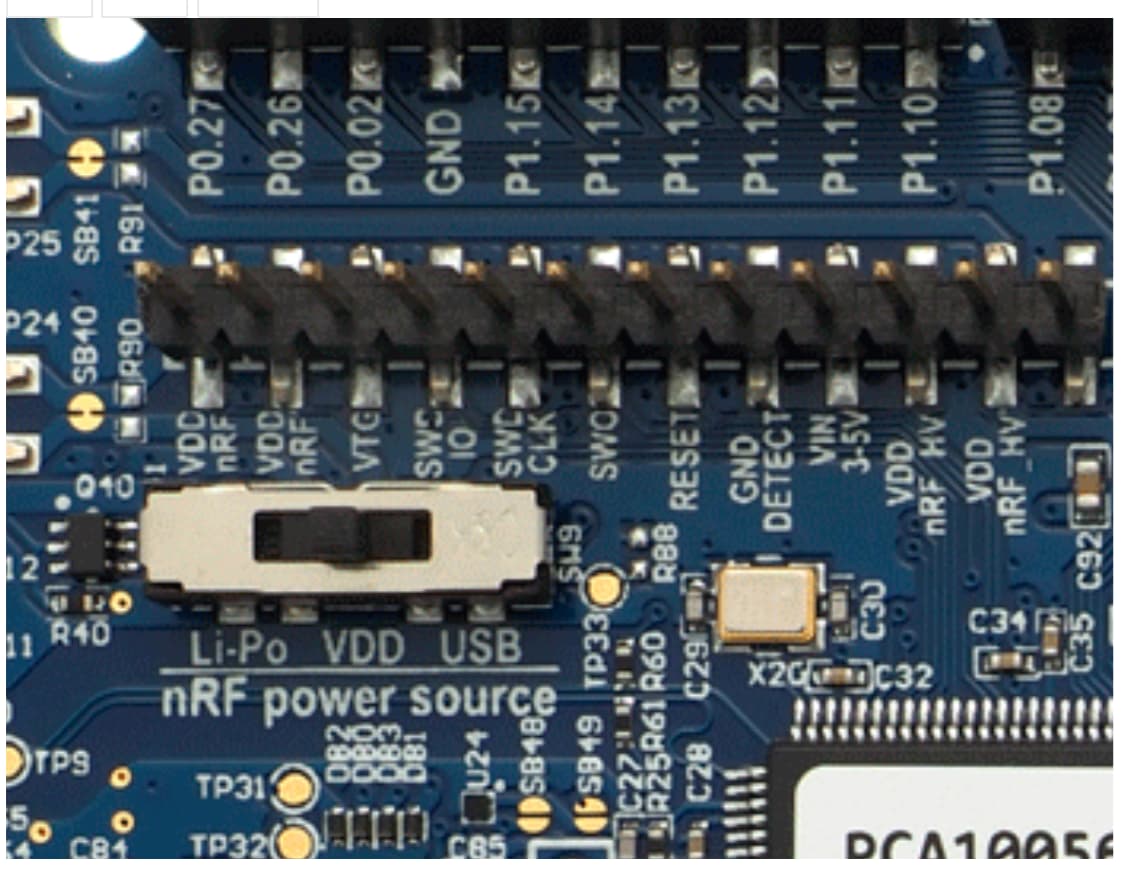
and welcome here, in the Nrf52840 be sure you are not missing a wire…![]()
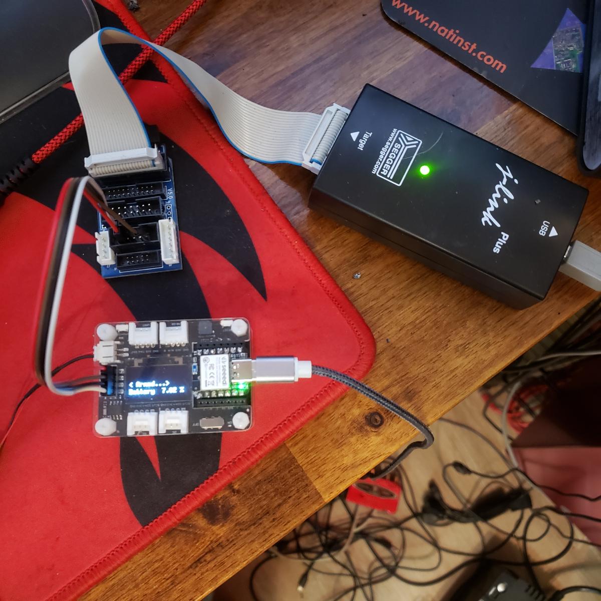
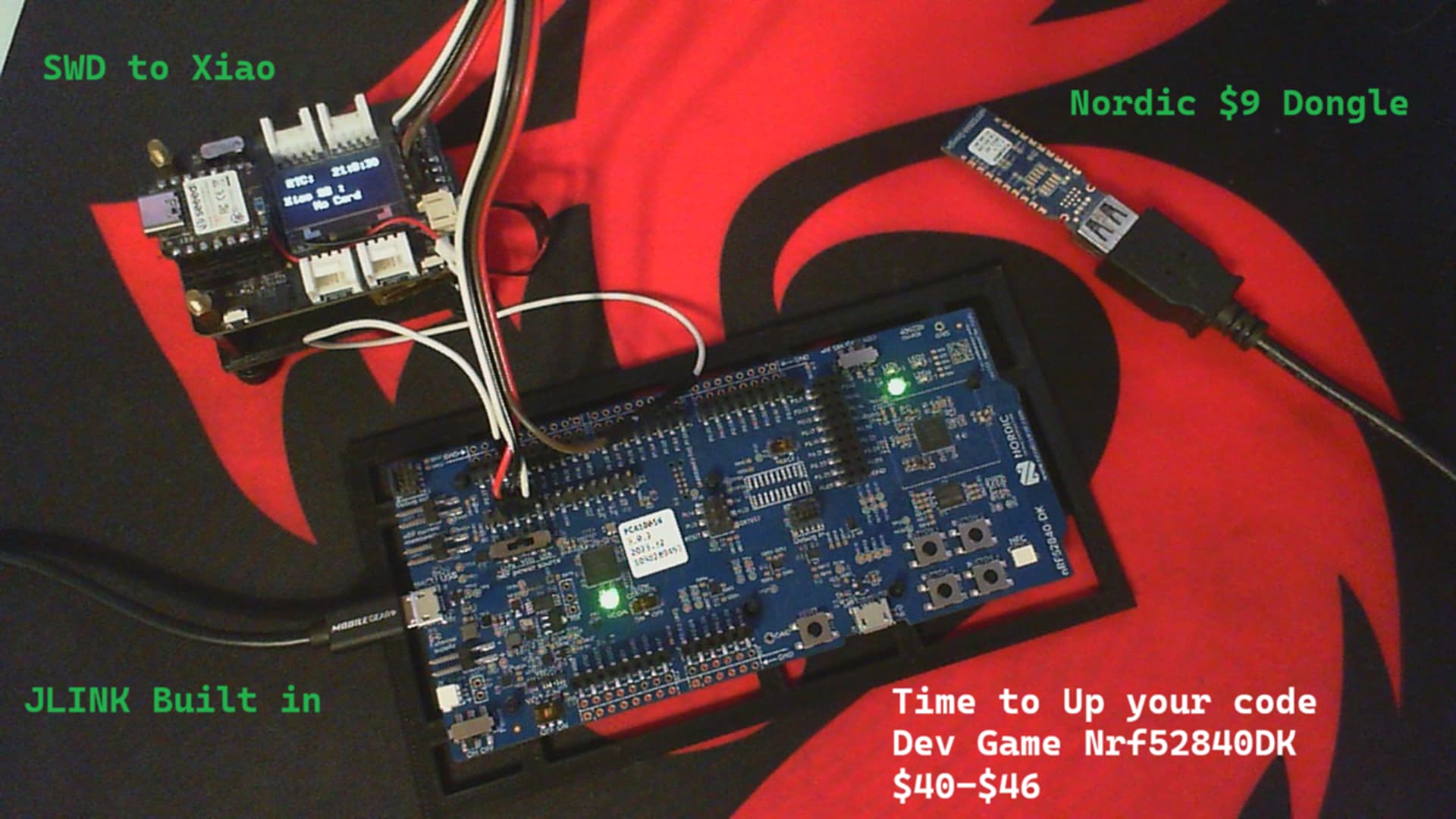
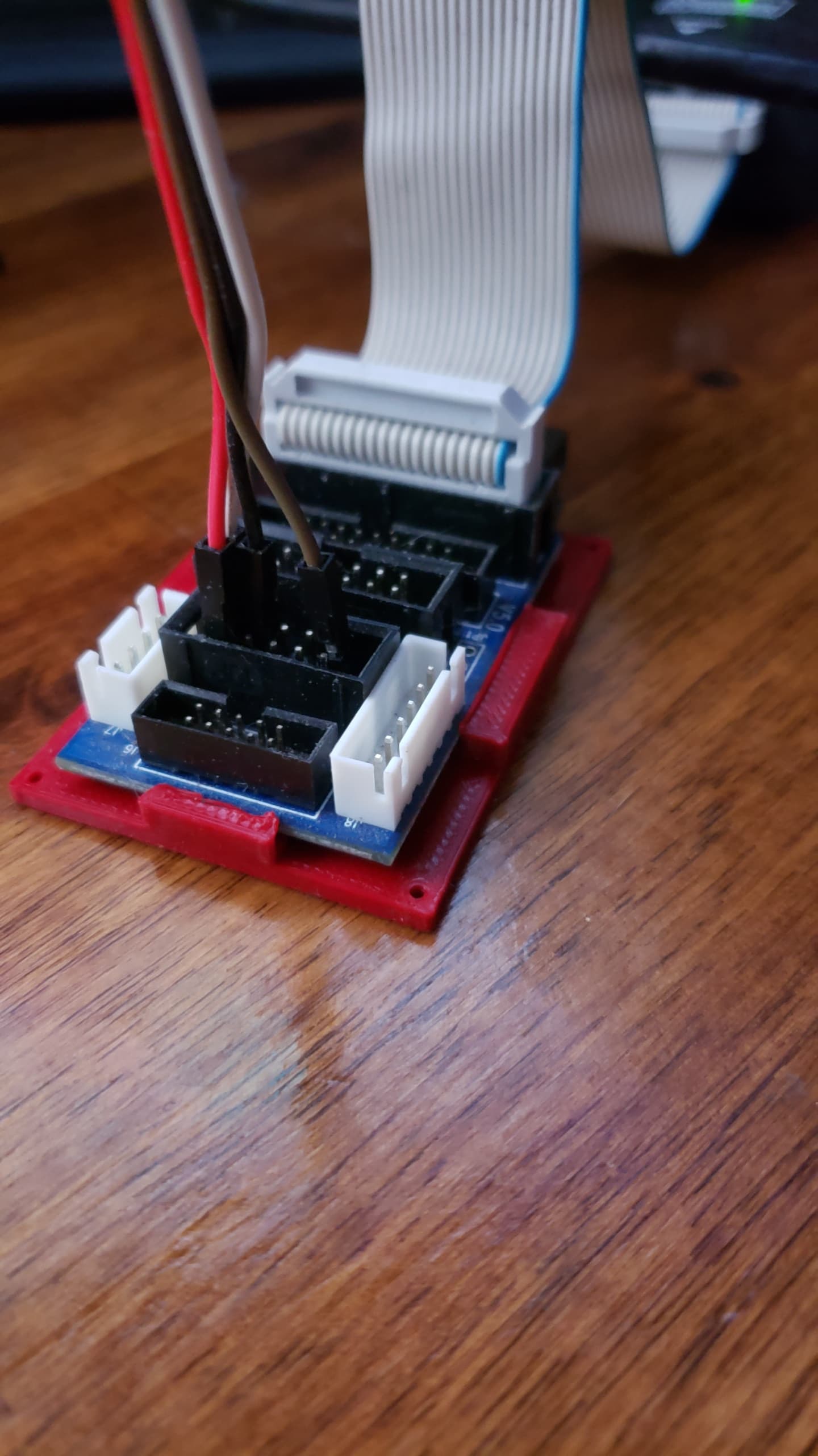
Can you describe the pin to pin connection you made, I use ALL of the Debugger models - JLink, Jlink Pro, Edu, and the built in versions for ALL DK nordic Boards, nrf52,53, and the the latest, Nrf54L15-DK board as well. Maybe some of these pics will help ![]()
There are other threads with more info as well, Search for Jlink ![]()
HTH
GL ![]() PJ
PJ ![]()
Did your battery arrive with the correct polarity wired as is?
1 Like
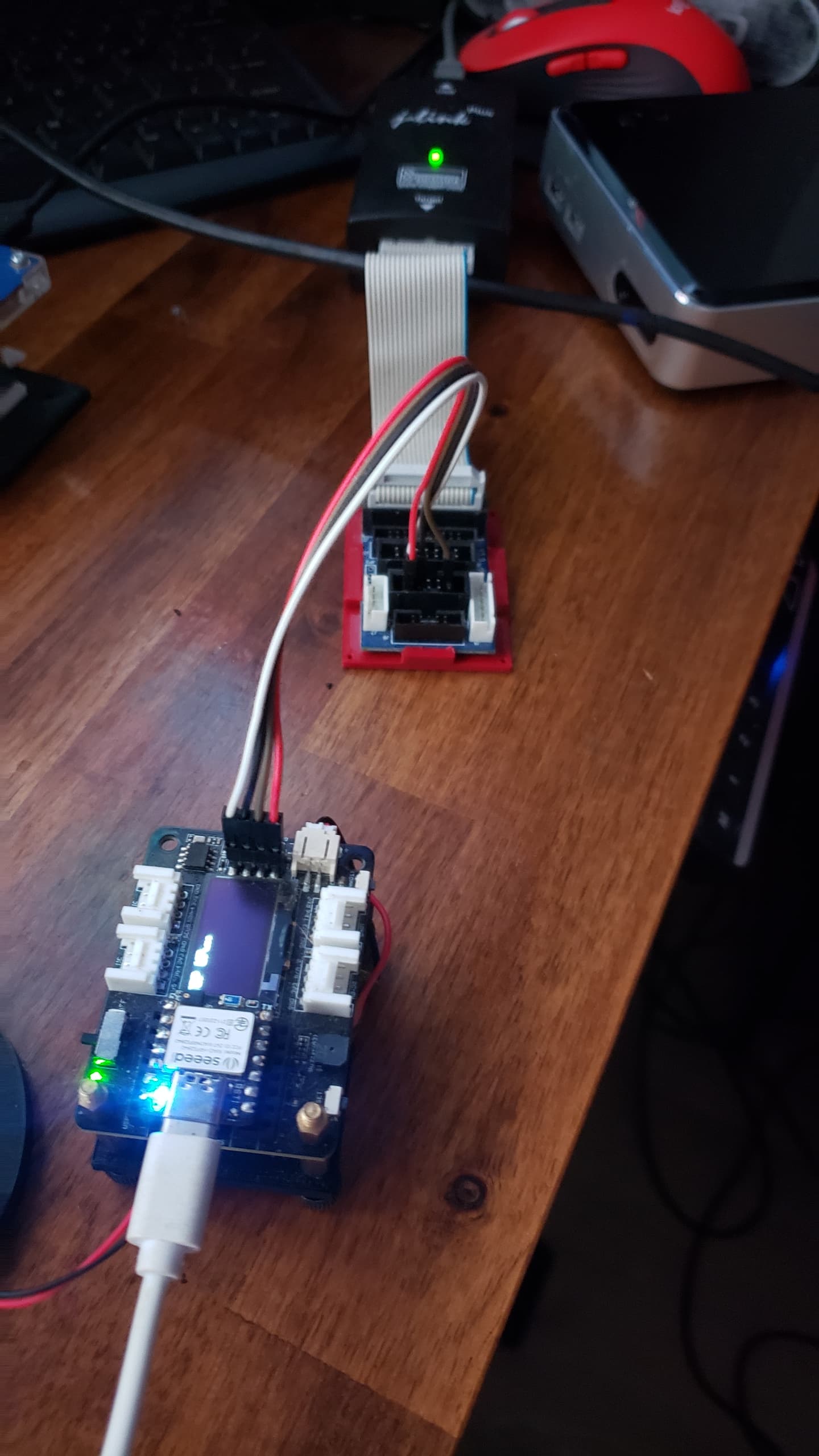
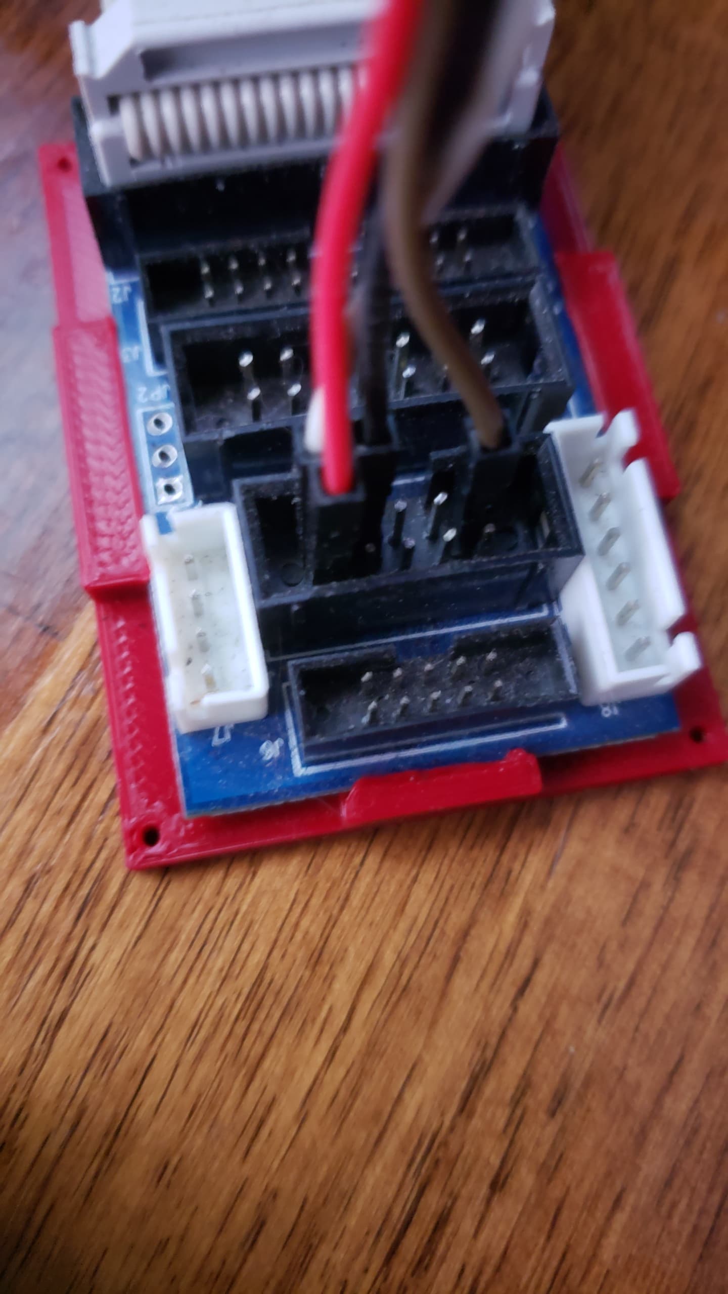
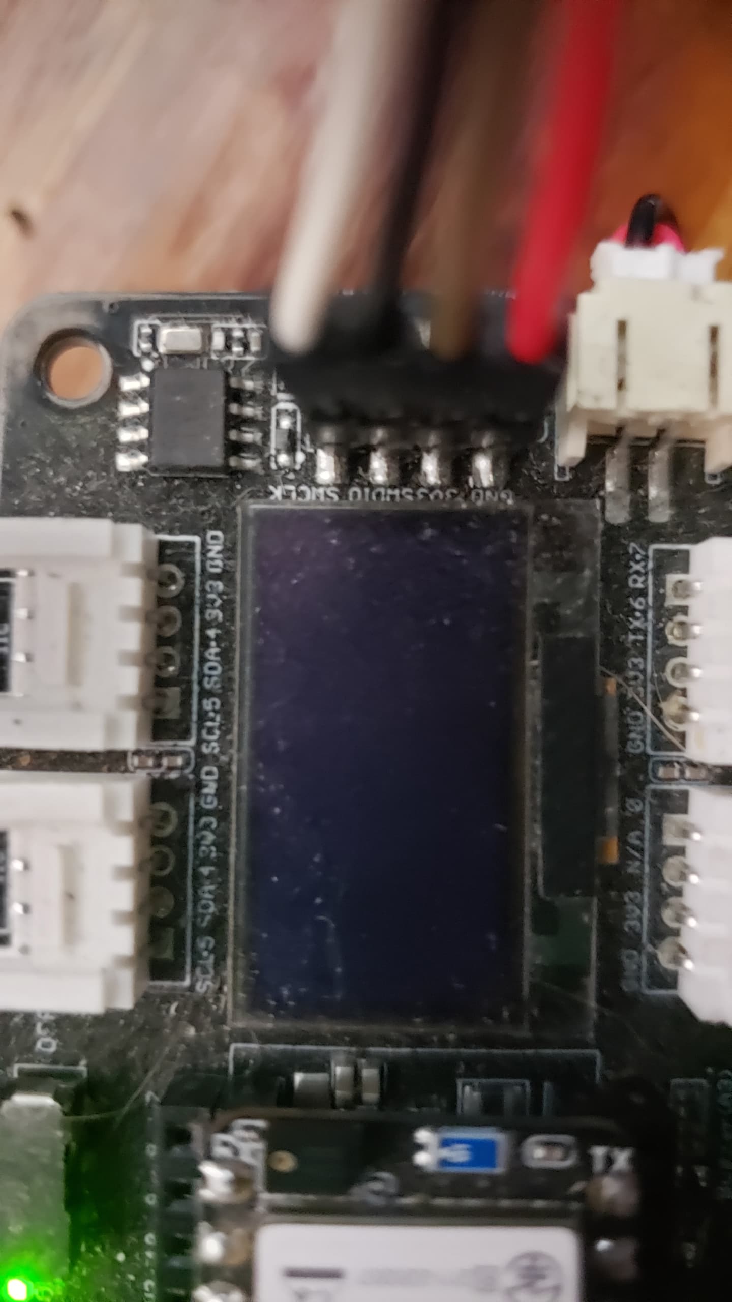
I use the Si-DBG1015A Simplicity Link debugger, and I had the following connections to the XIAO expansion board:
Board SWCLK to SWCLK/C2CK debugger
Board SWDIO to SWDIO/C2D debugger
Board 3V3 to VTARGET debugger
Board GND to GND debugger
Board RESET to RST debugger
XIAO MG24 powered via USB-C
Programming was possible once without errors, but then the XIAO expansion board failed.
Afterward, I soldered the debugger cables to the XIAO MG24 in the same order. Programming is now possible without problems. The XIAO expansion board has a short circuit on the 3V3 line coming from the XIAO. This is the reason why the XIAO is getting hot. I can’t think of any reason why the board failed.
1 Like
Hi there,
OK, looks to be correct. ![]()
Definitely a stranger things occurence not the norm AFAIK, SMH ![]()
You would have had to hooked the debuggers 5V ref or USBVCC to the Xiao’s SWD 3V3 (only electrical way I see that happening) If you were in Source mode the the 500ma. should be enough and then some, asking too much of the Xiao to power the Debugger and the Expansion board maybe ?? (elephant and a Rino= Elifino ![]() )
)
I have a Toasted XIAO ![]() , but it works except the Battery Charger doesn’t work anymore.
, but it works except the Battery Charger doesn’t work anymore.
Does the MG24 device still charge a battery ?
HTH
GL:-) PJ ![]()
FYI:
Specifications
Product specifications , If in the wrong mode ? (reaching ![]() )
)
4. Power Supply Modes The Simplicity Link Debugger is powered when connected to an host by the USB cable. When powered, the Simplicity Link Debugger can operate in two modes: 1.Sensing mode (default): the Simplicity Link Debugger senses the supply voltage of the connected device. In this mode, the current absorbed by the sensing circuitry of the debugger from the connected device is typically less than 1 µA 2.Sourcing mode: the Simplicity Link Debugger sources a fixed voltage of 3.3V to the device being debugged At start up, the Simplicity Link Debugger operates in sensing mode (default). This mode is intended for self-powered devices , i.e. the connected board has its own power supply or battery.
Another Dev has two units, the first one is very flaky with the Power switch(modes) if you press it too long it switches from Source to Sink ?
he likes it too btw ![]() but moans about the Software … LOL
but moans about the Software … LOL ![]()
1 Like
I use the same debugger and it generally works fine. I only use SWCLK,SWDIO, GND, PWR. No RESET or UART.
I sometimes have difficulties flashing my XIAO MG24’s however. In my case the reason is generally caused by the low height of the female headers on the expansion board.
This allows for misalignment of the pogo-pins under the XIOA MG24.
Apart from that the 'MG24 and Expansion “team-up” seems quite solid. All connections and GPIO modules seem to work OK.
(I haven’t tried/used the SD Card interface)
Unfortunately the XIOA<->Expansion pin header doesn’t have an “alignment” option so it is possible to misalign placement of the XIOA when inserting it onto the Expansion Board.
Placing it one pin down (missing pins 1 and 14, and yes, I have done that!) could cause some (permanent) damage due to the placement of the XIAO’s GND and 3V3 underside - especially with the XIAO powered by USB.
3V3 from the expansion will be grounded if the Debug Adapter and XIAO’s USB are on the same circuit.
5V from the XIAO would be shorted to GND but USB current protect should come into play (if connected).
I’d think that if my XIAO Expansion Board (and its multiple buck and boost switching regulators) dies, it’s probably due to that.
In hindsight, the placement of the power pins on the XIAO’s in the current position on both the standard (castellated) and SMD programming pins is a recipe for disaster.
Just to note - in my “experience”.
- The acrylic case doesn’t help.
- The battery connector is Positive Connection.
- USB can be connected during flashing.
- Turning the “power to target” option on the Si-DBG1015A works fine as does all the associated software. Press and hold the “Power Switch” button for 3 seconds to engage the 3V3 supply.
Pressing it again reverts back to “target supplied” immediately.
If you send me the hex/bin file that you used when the failure occurred, I can try here - I have all the same equipment…
2 Likes

The 3V3 and the 5V is lead out to the Connector as well
Seeed responded to my email and agreed to send me a replacement expansion board. Even in the replacement expansion board, I will be performing the same/similar hack as I list below to avoid this issue again.
Here is my analysis of this issue:
The Xiao uses TLV733P (a LDO) to produce the 3.3v supply. This is produced from the USB 5v (Vbus). By the USB spec, this 5v cannot disappear when the device is plugged into a host. So the on-xiao 3.3v is pretty ubiquitous.
The expansion board does 2 things: (1) takes Vbus and puts it through ETA6003 to charge the battery and produce Vsys. (2) this Vsys is then put through a step down converter (ETA3410) which produces another 3.3v source.
The 3.3v source from the Xiao and the 3.3v source from the expansion board are tied together directly without any form of back-feed protection.
Now, what could possibly go wrong?
Apart from the “it just feels worong to hook things this way”, I have 2 theories on what went wrong:
- The startup time according to the TLV733P data sheet is 800us typical. So let’s say ~1ms for the on-xiao 3.3v line to be up after the Vbus. The ETA* data sheets don’t explicitly state a startup time so if the combined time (ETA6003 + ETA3410 + any other delay due to external LC/RC networks) is greater than 1ms, we have the scenario where the xiao LDO is supplying 3.3v to the SW pin of ETA3410. Taking a quick look at ETA3410 there doesn’t seem to be any reverse current protection which means the 300ma from TLV733P should be enough to fry something which can cause the ETA3410 to fail causing the short.
- ETA3410 is a step down converter. It operates by switching the output voltage to match the desired voltage. So there is distinct on and off times. The TLV733P on the other hand is a passive component which stays always on. This means the output of ETA3410 can be held high during an off cycle. This probably puts some stress on the converter which over time fails.
I think (2) is what happened to me. I wasn’t plugging in/out the USB port so (1) is very unlikely. The fact that the failure happened when I was enabling USB drivers is probably just a coincidence.
What can you do?
Well, I just desoldered both the ETA6003 and ETA3410 from the expansion board with a hotair gun and stopped using the battery connector on the expansion board and and soldered battery connectors to the xiao board. With that, things seem to work for me.
You could also just not connect the 3.3v from the xiao to the expansion board. This is the cleanest solution if you have a working xiao board and the expansion board. Before soldering the male headers to the xiao, just pull out the pin corresponding to the 3.3v pin (or just cut it with a clipper) so when you insert the xiao board on the expansion board, the 3.3v from the xiao is isolated from the 3.3v on the expansion board. I plan to do this to the replacement expansion board.
PS. The desoldering bit was tricky as the headers and the display are very close to those components. I used lots of kapton tape to protect the other components and still managed to damage the OLED :). Luckily, I had some spares so I replaced the OLED and everything was solved.
4 Likes
The following post is a useful reference for this issue.The following post is a useful reference for this issue.
3 Likes
It is so good to have long time members who know where to look for things! Thanks MS!
Seeed Studio should rethink its hardware design.
The soldering version works for testing. If the XIOA MG24 works the way I need it to, I’ll make a pogopin socket version for a breadboard. The XIAO expansion board would have been a time-saving solution for programming, but unfortunately didn’t work as expected. Thanks everyone for your help!
Unfortunately I don’t have a battery to test this.
I just use the usb to flash the MG24 via the built in SWD programmer. Just as fast as the JLink option. No expansion board or soldering required.
Expansion board is for development of additional IO based software.
My more “permanent “ development board has soldered SWD, and Reser.
but it doesn’t work with simplicity studio or have I missed something?
It can be used with Simplicity Studio - I’ll have a look through my projects to see how I did it. Been a while.
I generally don’t use the USB/SWD approach for flashing/debugging in 'Studio as I have my “development platform” which has a JLink/SWD connection, additional reset button and battery connections soldered in.
Probably the easiest would be to use VSCode and the Silicon Labs extension, Cortex Debugger and OpenOCD with a custom launch.json.
1 Like
I will take a look at it in the future. Maybe you could write how you did it?
Truth be told, I’ve burned through this expansion board myself. I dragged our engineer along to see what was going on in the first place. We had a couple of new boards reclaimed later to test, but none of them could reproduce the burn. If you have a way to reproduce it stably, by all means let us know and we can cover the cost of all your boards. But please do keep yourself safe, thanks in advance (hugs)
1 Like
i can do it all day long by plugging in the XIAO wrong!
Haha, of course we’ll review it.
if it is one pin back i think you get USB5v shorted directly to ground