So pretty sure OP Was using just base Nrf54840 Xiao and NOT the “Sense” version. so no IMU or PDM.. Plenty O’ Room..
WARNING …
I can’t emphasize this enough, look VERY, VERY closely at that end of the board. There LIVES a LONE resistor, probably the smallest Known to man I’m betting it’s almost not visible to the Naked eyeball,
so close to the edge , it should be Illegal
Beware of it and the traces around it.
Yes, @ PJ_Glasso is correct…
@ cgwaltney it was the basic XIAO without the PCM chip. And the wire was added into the antenna “circuit” GND without removing the antenna chip itself and replacing it. On the basic XIAO the PCM footprint GND was the easiest/safest place to add the wire to affect the antenna circuit. But not a substitute for replacing the original antenna and the need to re-tune the antenna circuit via the FEED.
I guess whar i am asking is i thought the blue resistor looking thing is the antenna… are you saying some of the 6 pins adjacent to it are also antenna pins?
No, that’s part of the PDM circuit, but the GND pin of that circuit is common to the antenna chip’s GND side. And since the PDM is empty, it’s safer/easier to solder a wire there instead of the the chip’s side contact. This is by no means a replacement for the antenna chip, just augmenting the RF strength of the existing chip antenna.
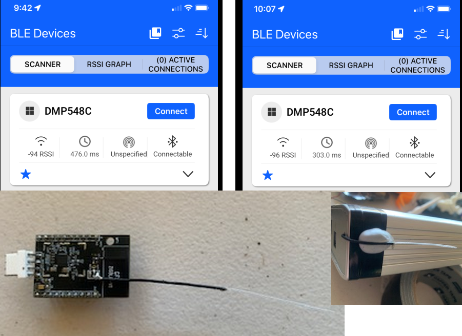
If you want to have a larger impact, replace the antenna chip with a better circuit/setup. The wire I added gave a 10db increase in signal inside my home which allowed me to get a reliable connection in a farther room which I was not able to get before.
Hey what do you mean about re-tunning the antenna? If i were to completely replace the antenna, wouldn’t removing the blue antenna completely, and then solder the signal of the new antenna to the “feed” and the shielding to the ground be enough? Isn’t the 2.4ghz router style antenna already tuned?
i think the point being that you cannot use 2 antenna… so i would not expect that leaving the “resistor” antenna in circuit with an external antenna would work very well IMO… also all antennas can be tuned with an in circuit analizer to focus in on one frequency for efficiency…
I got 10db in my setup by adding “two” antennas. It was not a scientific outcome or design, just an ad hoc solution that worked for me in that situation. It is not the way to do it “properly”, if you want to replace the existing chip antenna with your own “proper” design.
So i soldered a 2.4ghz antenna on “feed” and to the ground. Results look promising. Just with a 3 cm wire soldered to the ground i got +10db , and with the antenna +5-7 db more than that. Range with the antenna is 100m+ in LOS
I tried to solder a 30mm wire to the PCM pads, that’s not easy! I think I used a too rigid wire and when I tried to bend it a little bit afterwards, it removed the whole pad it was soldered on.
I really think Seeedstudio should replace the pcb antenna with an ipex connector and an external antenna. Even if they only provide a tiny one at least we would have an easy way to install a better antenna.
I soldered a (very) flexible shielded cable to the original chip antenna solder pad and then removed 31.2 (ish)mm of the shielding for a low cost hack.
I also found this single wire antenna worked best with a significant ground plane which suited my application, viz routing RF signals to outside of steel housing.
NB! There was no budget (space or cost) for a “normal” antenna with SMA connectors.
That was a while ago and the products have been installed on site.
I knocked up another one for you a few minutes ago… tested with Zigbee/BLE to Zigbee2MTT and one of my EFR32MG21 test modules.
I don’t have time to do a full test with a Radio Test Module and Spectrum Analyser but the results are the same as originally tested.
So I would try the nRF54L15 with External Ant. Setup. Not only will it be less power draw an Battery but the Non Sense Version is Very , very good for Long Range BLE apps coupled with the 2M Phy Hard to beat for battery vs link budget and bandwidth. I’m testing some now and Early results are pretty steller. Longer distance and higher throughput less power, Considerably higher receive sensitivity.
No soldering, just some code learn’in , The nrf52840 juice in this case Ain’t worth the squeeze with the more superior part available IMO.
But it’s NOT ALL good News… I do have some strange NON booting on Battery only issues?? if I connect a USB power Only for less than 15 seconds , it boots and runs forever on battery. Initially I have to have a 5vUSB present to run. WIP
On the original that is what we did - removed chip antenna and soldered onto feed (core) and ground (shield).
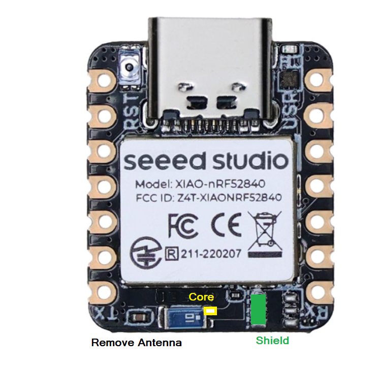
On the sample I created this morning I disconnected the PCB antenna and soldered the core and shield to the pads where the UFL connector would normally be placed.
ok, thanks. The pads are so tiny that you really need a fine soldering iron tip… and being able to make the solder without causing a short circuit between the two is beyong my abilities
Yes, pretty tight tolerances. After removing the antenna, you may be able to solder to the antenna pads in the positions shown below in yellow and green?
The shield holds the wire in place.