I understand that the XIAO nRF52840 has a bluetooth antenna, but I am still looking for ways to improve its range. either ArduinoBLE (library tweaks) or hardware based.
can someone stir me to the right direction, please and thank you…
Hi, I don’t think there are additional places for additional bluetooth antenna for wider range, nor the software way. Sorry.
Also, the 5V and 3.3V will be the best input voltage. Otherwise the board might be damaged.
Hope this can help you!
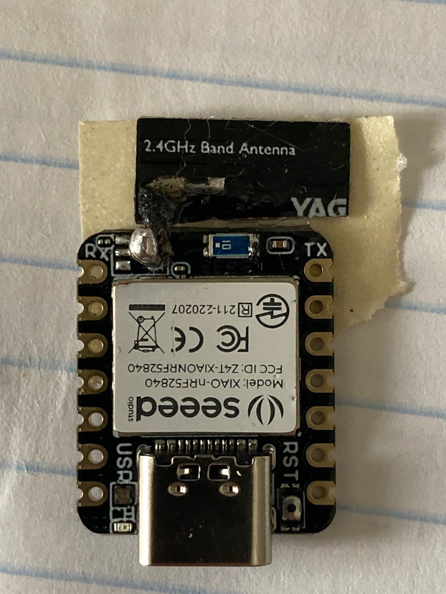
Make sure you only solder to one side of the unpopulated PDM pins. Or you can solder (carefully) directly to one of the two pins next two each other on the antenna chip.
.
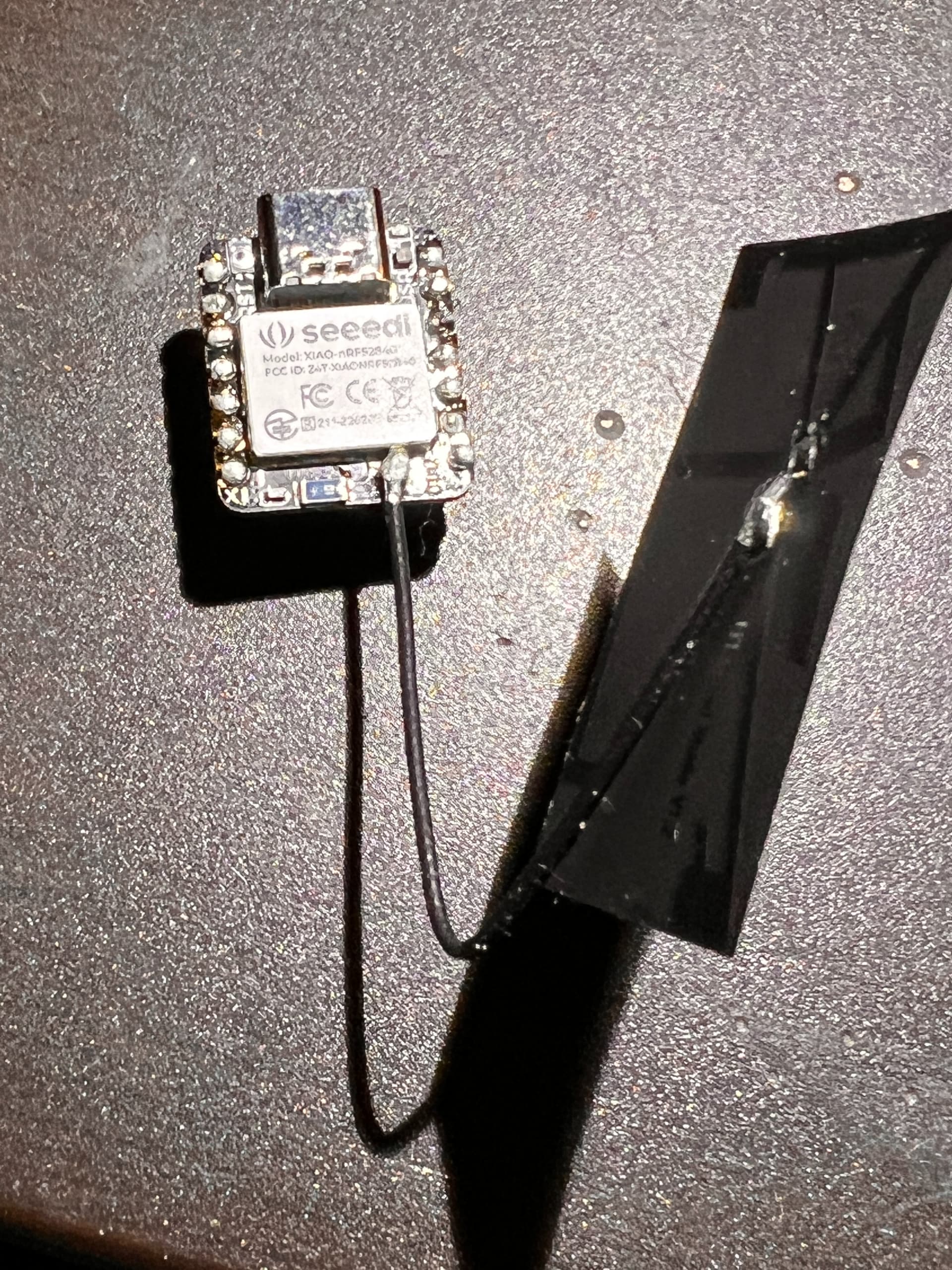
Had to do it like this because the PDM has a mic on the Sense-version. Works great so far, despite that I have bridged two pins on the antenna-chip by accident, doesn’t seem to make a difference. I used 0.5mm enameled copper wire ca. 30mm long.
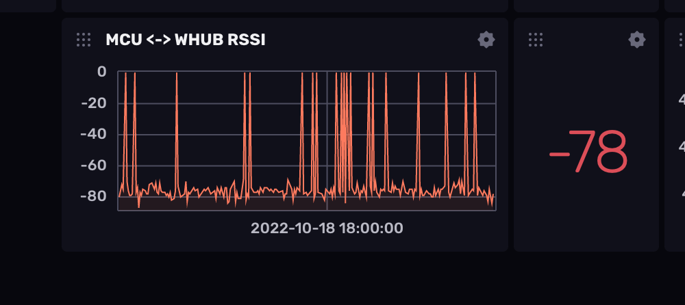
I soldered a 5" piece of solid core wire to the left side of the existing antenna chip. The two pads on that side seemed larger to me. I did this on both of the Sense’s I’m working with and the range improved dramatically. They can even talk through the floor of a house.
I don’t have the units anymore, but essentially, just solder a piece of wire to the right side of the blue BT chip. Right side assumes the USB connector is at the 12 o’clock position. When I soldered it to the left side as I mentioned above, the solder contacted the diode next to it. But the right side of the BT antenna chip has nothing close to it.
Hey! so from the images bellow, it looks like you guys are soldering the antenna to the ground. How does this help? Shouldn’t the antenna be soldered on the feed, and also disconnect the old antenna?
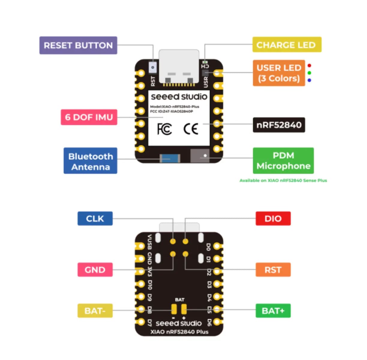
It looks like I cant include images or links in my post, but from the schematics, the lower pin next two each other on the antenna chip is ground and the upper is the signal.
So , First I doubt the Juice is worth the squeeze… Results are hit and miss, not really meant for it, I think soon there will be another option that can choice between Internal or EXT, like on the C6. I wouldn’t waste my time the circuit has to be carefully tuned as not to damage the Xiao.
Not all those antennas’ are created equal, DON’T use one for Lora, meant for WiFI or visa-versa.
HTH
GL PJ
BTW, Nordic makes a range booster chip for BLE, seeed may offer a sandwich board for it would be great.
not to disagree but i have had success with using the white antenna above (2.4ghz) for LoRa… also the black (910 mhz)… they both seem to work equally well on my moonshots… I understand this should not be so
I’m making a project just for fun! So tinkering around is welcome!
That would be a solar lora node mount in my rooftop, which would need the extra bluetooth range if I can squeeze some! Soldering in these tiny contacts sounds fun!
Are my assumptions correct though?
Ie - remove the old antenna, and just solder the signal to “FEED” and the shielding to GND?
Am i coming in too late… but you wouldnt want to remove the PDM microphone Chip… you would want to remove the Antenna Chip right? this image is something else right? which side of the antenna chip is ground? left or right?