Hi,
Hope someone can help. I’ve been using the XIAO Expansion Board (XEB) now for a while and it’s been great. I have a BME/BMP280 connected to the breakout sockets on the XEB and am using the OLED display to show a temperature graph. I recently added the buzzer to give a short chirp when the graph reaches 100 points and restarts from 0. It was working perfectly yesterday when I unplugged the USB cable from my laptop. This morning when I plugged it in I got no response from anything. No connection ding from Windows, no OLED display, no flashing green LED on the XEB, and no LED on the XIAO. Unplugged the XIAO from the XEB and it works fine. Power LED comes on, it’s recognized by my laptop and I can upload to it with success. I plug it back in to the XEB and again, nothing. I did notice that there is some heat coming from the chips on the XEB that are located between the headers. I even tried uploading the “BareMinimum” sketch to the XIAO and plugging it in. Still nothing.
Thoughts???
Dan
Hi Dan
My XEB broke down just like yours.
Below is a link to my post.
Hi msfujino,
Did you get a reply from tech support regarding your SYS_3V3 observation? I just received my replacement board from RobotShop but I’m afraid to try in in case it fries again. Oh well, no guts, no glory. If it dies I’ll just have to wait for another one. Did you get a replacement?
Seems like a component failure to me as well. Something must be dragging down the voltage when the XIAO is plugged in.
Dan
Hi Dan,
See my post at the end of the link. Seeed says it’s okay, but I cut the circuit pattern and use the two SYS_3V3s separately. It’s working fine for now.
Hi msfujino,
So which trace did you cut? Your board worked normally after that?
Dan
Only one place needs to be cut.
If you don’t want to cut it, you can also remove the XIAO pin header.
Hi msfujino,
Update on my XEB.
So I cut the trace in the pic that you sent and the XIAO had power and worked. The only elements that worked on the XEB were the ones that required no power (RESET button and A1_D1). I measured voltage at 3.3V pins on Grove connectors and got nothing so looks like the ETA3410 circuit is done. I then thought I would try using an external 3.3V supply (I used a breadboard supply) and feed it in through one of the Grove connectors. I had the “Hello World” sketch loaded onto the XIAO. It worked but the LED on the breadboard supply went out. I then measured the output of the supply while the OLED was displaying. I got around 1.9V. So looks like before I cut the trace the XIAO was trying to power the XEB but couldn’t supply the required current and was dragged down. The breadboard supply has a higher current rating and was able to barely keep up (didn’t keep it powered up very long in fear of burning it up). Incidentally, the buzzer also worked but I did not try the RTC or SD. I suspect that they will work.
So I’m thinking my next step is to isolate the ETA3410 circuit and try the external supply again to see if my supply stays at 3.3V. Unfortunately it looks like taking the ETA3410 out would also disable the battery circuit. What are your thoughts? Also, do you know what FB1 and FB3 are? Auto resettable fuses maybe?
Update to my update:
I pulled the XIAO out of the XEB socket and injected 5V directly into 13 and 14 on the XIAO header. I then measured voltage on the ETA6003, pin 2, got 5V. I then measured at pin 15 (VSYS) of ETA6003, got nothing. I guess its the ETA6003 that’s fried and not the ETA3410.
Thanks,
Dan
Hi Dan
I returned a broken XEB and got a new one, so I couldn’t analyze it in detail. I think it’s a malfunction of the ETA6003 as in your case. FB1 and FB3 are ferrite beads.
Both of our XEBs seem to have had initial defects in the parts.
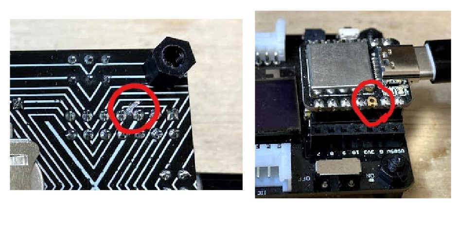
I only use XEB for debugging, so I was only expecting to power XEB from XIAO’s USB_5V. In this case, 3.3V generated by XIAO is output to the 3V3 terminal of XIAO, and it collides with SYS_3V3 generated by ETA4310 of XEB. For peace of mind, I cut the circuit as shown in the picture.
However, when powering only with a battery without using USB, it is necessary to power from ETA3410 to XIAO. Do not cut the circuit. I’m worried that you haven’t cut the new XEB circuit yet .
Hi msfujino,
Yeah, that makes sense regarding powering of the XIAO from the ETA4310 when supplied with battery only.
So you’re saying DO NOT cut the trace on the new board and hope that the new ETA6003 does not die like the last one?
Dan
Hi Dan
Seeed says it’s okay, so we may just have been out of luck. You can avoid SYS_3V3 collisions by cutting the pattern and feeding XIAO from another power source.
Looks like this still an issue with exp boards shipped in May/June 22 at least. Thanks @msfujino for the trace cutting hint. That at least made my two usable with SWD/JLink debugger.