XIAO ESP32S3 & Wio-SX1262 arduino ide LoRa error

The Meshtastic features work well; however, I can’t use it for a simple P2P LoRa connection. I am using the simple LoRa code example to transmit and receive. Ended up with LoRa not initialized error. Do I need to define pins first?

#include <SPI.h>

#include <LoRa.h>

int counter = 0;

void setup() {

Serial.begin(9600);

while (!Serial);

Serial.println(“LoRa Sender”);

if (!LoRa.begin(915E6)) {

Serial.println("Starting LoRa failed!");

while (1);

}

}

void loop() {

Serial.print("Sending packet: ");

Serial.println(counter);

// send packet

LoRa.beginPacket();

LoRa.print("hello ");

LoRa.print(counter);

LoRa.endPacket();

counter++;

delay(5000);

}

HI there,

YEP… in a word :smile: :+1: seems as it works best that way, add some code to verify the pins You asign are the ones it knows , ie. CS in cases of SPI, or SS in Flash or SD card code. better to know for sure than jump without the Net , " Capisce :pinched_fingers:"

Best question of the week. IMO… also check @msfujino posts on the P2P scene.

HTH
GL :slight_smile: PJ :v:

ps. can you use the code tags and fix that, " </> " above just paste it in there so it’s readable, TNX. you’ll get better help too that way. :v:

If your LoRa module does not use the default pins (or if you’re unsure), you can define the pins for the LoRa module manually before initializing it. You can do this by using LoRa.setPins() in your setup function.

im supposed to get one for christmas

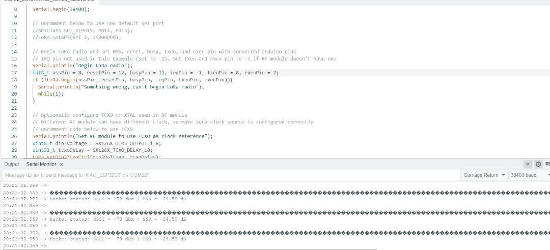
Thanks for the comments. Tried out several pins, had a seeed ranger helped out. Managed to create transmit and receiving code, both Lora initialised. One was transmitting, but the receiver did not receive the message. No idea what went wrong, but here are the codes for the transmit.

#include <Arduino.h>
#include <SX126x-Arduino.h>
#include <SPI.h>

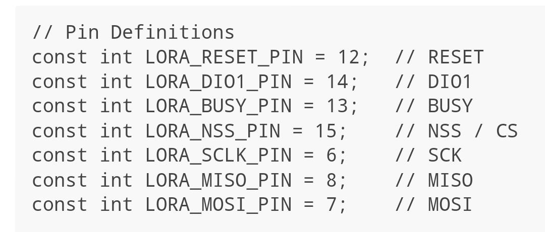
// Pin Definitions (based on Seeed Studio Wiki)
const int LORA_RESET_PIN = 12;  // RESET
const int LORA_DIO1_PIN = 14;   // DIO1
const int LORA_BUSY_PIN = 13;   // BUSY
const int LORA_NSS_PIN = 15;    // NSS / CS
const int LORA_SCLK_PIN = 6;    // SCK
const int LORA_MISO_PIN = 8;    // MISO
const int LORA_MOSI_PIN = 7;    // MOSI

// LoRa Settings
#define RF_FREQUENCY 868E6   // Asia Frequency
#define TX_OUTPUT_POWER 22   // dBm

// Buffers
#define BUFFER_SIZE 64
static uint8_t TxdBuffer[BUFFER_SIZE];

// LoRa Radio Events
static RadioEvents_t RadioEvents;
hw_config hwConfig;

// Function Declarations
void OnTxDone(void);
void OnTxTimeout(void);

// LoRa Initialization
void setup() {
  Serial.begin(115200);
  delay(1000);

  Serial.println("Initializing LoRa Transmitter...");

  // Configure LoRa Hardware
  hwConfig.CHIP_TYPE = SX1262_CHIP;
  hwConfig.PIN_LORA_RESET = LORA_RESET_PIN;
  hwConfig.PIN_LORA_NSS = LORA_NSS_PIN;
  hwConfig.PIN_LORA_SCLK = LORA_SCLK_PIN;
  hwConfig.PIN_LORA_MISO = LORA_MISO_PIN;
  hwConfig.PIN_LORA_MOSI = LORA_MOSI_PIN;
  hwConfig.PIN_LORA_DIO_1 = LORA_DIO1_PIN;
  hwConfig.PIN_LORA_BUSY = LORA_BUSY_PIN;

  // Initialize LoRa Hardware
  lora_hardware_init(hwConfig);

  // Setup Radio Event Callbacks
  RadioEvents.TxDone = OnTxDone;
  RadioEvents.TxTimeout = OnTxTimeout;

  // Initialize the Radio
  Radio.Init(&RadioEvents);
  Radio.SetChannel(RF_FREQUENCY);

  // Configure TX Settings
  Radio.SetTxConfig(MODEM_LORA, TX_OUTPUT_POWER, 0, 0, 7, 1, 8, false, true, 0, 0, false, 3000);

  Serial.println("LoRa Transmitter Initialized.");
}

void loop() {
  // Prepare and Send Data
  const char* message = "Hello LoRa!";
  memset(TxdBuffer, 0, BUFFER_SIZE);
  strncpy((char*)TxdBuffer, message, BUFFER_SIZE);

  Serial.printf("Sending Message: %s\n", message);
  Radio.Send(TxdBuffer, strlen(message));

  // Wait before sending the next message
  delay(3000);  // Adjust this value as needed
}

// Event Callbacks
void OnTxDone(void) {
  Serial.println("Transmission Complete.");
}

void OnTxTimeout(void) {
  Serial.println("Transmission Timeout.");
}

and here is the receiving code

#include <Arduino.h>
#include <SX126x-Arduino.h>
#include <SPI.h>

// Pin Definitions
const int LORA_RESET_PIN = 12;  // RESET
const int LORA_DIO1_PIN = 14;   // DIO1
const int LORA_BUSY_PIN = 13;   // BUSY
const int LORA_NSS_PIN = 15;    // NSS / CS
const int LORA_SCLK_PIN = 6;    // SCK
const int LORA_MISO_PIN = 8;    // MISO
const int LORA_MOSI_PIN = 7;    // MOSI

// LoRa Settings
#define RF_FREQUENCY 868E6   // Asia Frequency
#define RX_TIMEOUT_VALUE 3000

// Buffers
#define BUFFER_SIZE 64
static uint8_t RcvBuffer[BUFFER_SIZE];
static uint16_t BufferSize = BUFFER_SIZE;

// LoRa Radio Events
static RadioEvents_t RadioEvents;
hw_config hwConfig;

// Function Declarations
void OnRxDone(uint8_t *payload, uint16_t size, int16_t rssi, int8_t snr);
void OnRxTimeout(void);
void OnRxError(void);

void setup() {
  Serial.begin(115200);
  delay(1000);

  Serial.println("Initializing LoRa Receiver...");

  // Configure LoRa Hardware
  hwConfig.CHIP_TYPE = SX1262_CHIP;
  hwConfig.PIN_LORA_RESET = LORA_RESET_PIN;
  hwConfig.PIN_LORA_NSS = LORA_NSS_PIN;
  hwConfig.PIN_LORA_SCLK = LORA_SCLK_PIN;
  hwConfig.PIN_LORA_MISO = LORA_MISO_PIN;
  hwConfig.PIN_LORA_MOSI = LORA_MOSI_PIN;
  hwConfig.PIN_LORA_DIO_1 = LORA_DIO1_PIN;
  hwConfig.PIN_LORA_BUSY = LORA_BUSY_PIN;

  // Initialize LoRa Hardware
  lora_hardware_init(hwConfig);

  // Setup Radio Event Callbacks
  RadioEvents.RxDone = OnRxDone;
  RadioEvents.RxTimeout = OnRxTimeout;
  RadioEvents.RxError = OnRxError;

  // Initialize the Radio
  Radio.Init(&RadioEvents);
  Radio.SetChannel(RF_FREQUENCY);

  // Configure RX Settings
  Radio.SetRxConfig(MODEM_LORA, 0, 7, 1, 0, 8, 0, false, 0, true, 0, 0, false, true);

  Serial.println("LoRa Receiver Initialized. Listening...");
  Radio.Rx(0);
}

void loop() {
  Radio.IrqProcess();
}

// Event Callbacks
void OnRxDone(uint8_t *payload, uint16_t size, int16_t rssi, int8_t snr) {
  BufferSize = size;
  memcpy(RcvBuffer, payload, BufferSize);

  Serial.printf("Received Message: %.*s\n", size, payload);
  Serial.printf("RSSI: %d dBm | SNR: %d\n", rssi, snr);

  // Resume Listening
  Radio.Rx(0);
}

void OnRxTimeout(void) {
  Serial.println("Receive Timeout.");
  Radio.Rx(0);
}

void OnRxError(void) {
  Serial.println("Receive Error.");
  Radio.Rx(0);
}

Update 1. @Hendra Kusumah suggested using (GitHub - chandrawi/LoRaRF-Arduino: Arduino library for basic transmitting and receiving data using LoRa and FSK modulation . He tested on Heltec V3 (which uses ESP32S3 and the same SX1262.
While it worked for the Heltec module, it did not work for this one. It seems the transmitter seems to be transmitting fine. The receiver did not.

Where are you getting your connection data for the sx1262 module.

@nroselnik

Getting LoRa P2P working with this is really important

@PJ_Glasso

@cgwaltney

@captainchaosrules

@f5ozf
@Marvin-YYC

@bambuino

Need checked connections for LoRa:

Reset, DI01, busy NSS
sck, miso, mosi

When these are correct we have a better chance of getting these boards working

Hi there,

Yes, I would agree… SO the set I ordered for testing I’m am praying slipped by b4 NON-sense over takes our side. I beleive they shipped so I’ll test the P2P for a project a good distance away.

I know they work 20km in one example clear line of sight more or less. I’m not going anywhere near that far so, these in a stack with the GPS should be a great test. :call_me_hand:

GL :slight_smile: PJ :v:

Never thought I would see a dozen Eggs more expensive than a Xiao :face_with_peeking_eye: :clown_face:

i noticed the windshield blocks signal… I was not getting on dashboard but got on hood… my area is flat so trying to do tests across likes and rivers… I need to get a wip antenna

the daughter board comes off too easy… I wonder if the 14 pin unit will work better

These settings do not work for me. Does anyone have working settings for the xiaoEsp32s3-sense with the wio-sx1262

Meshtastic has settings that kind of work for me

https://flasher.meshtastic.org/

always use this website to update meshtastic firmware

The meshtastic flasher works great, that is not what I am trying to do, I want LoRa P2P working directly between the xiao’s no meshtastic needed. I just can’t get the radioLib pingpong.ino working.

examples/SX126x/SX126x_PingPong/SX126x_PingPong.ino

Hi there,

So is there a BSP involved? Which is compiled with it now?
maybe roll back 2 and try again?
HTH
GL :slight_smile: PJ :v:

I figured it out, minor issues.

1 Like

Hi there,

That is Great and all , but a little more info on it would maybe help others too. Unless it’s embarrassing… :blush: LOL we won’t care SOLUTIONS is what makes this place a source for us All

HTH
GL :slight_smile: PJ :v:

plus you get to mark your own post as the Solution. :+1: Win/Win

The code above only originally ran if I incorrectly had the DI01 and BUSY switched I eventually figuered it out with both an arduino portentaH7 and a rakwireless 2270 sticker tracker running lora P2P. When the other boards sent a message the above code worked but it would not start by itself.

Adding #define INITIATING_NODE

Allowed the code to send its first transmission and then continue the pingPong.

This is just the starting point. Next combining meshtastic, then LoRaWan for thr helium network

Then how to talk to the sx1262. Does anyone know if it uses AT commands?

1 Like

Hi there :blush:

Now we are talking… :v: that is awesome, Helium too :+1:
I should have my set very soon , so Ican check

GL :smiley: PJ

1 Like

Does anyone have a basic LoRaWan OTAA that works with this board. On the meshtastic side I cant even see any of the encrypted gibberish. I must have a setting that is different for my lora p2p than meshtastic. I feel like I should at least see the header? Anyone got ideas?

Deleted as I’m not sure it’s right and don’t want to cause confusion for others that come across it.

1 Like

I’m having similar issues with XIAO RP2040 and Wio-SX1262. I’m trying to use the Radiohead library which works well for me with XIAO RP2040 and generic RFM95 boards. But the Arduino test code hangs on driver.init() after setting up with

RH_SX126x driver(D4, D1, D3, D2); // NSS, DIO1, BUSY, NRESET

I’ve gone over the Pin definitions many many times but I suspect there is something wrong there.

I noted the Wio-SX1262 that I purchased from Seeed has a different pinout to other photos I’ve seen. Despite being called V1.0.