Hi there,
Ok well, some progress.
Try slowing down the SPI speed for the SD card.
#define SPI_FREQUENCY 10000000
Sometimes SD.begin() is where this falls over if another SPI device was already initialized at a much higher clock.
Sometimes , Even though the TFT has no MISO, if its CS is left low or floating when SD.begin() starts, it can still interfere with bus setup.
Add this or something like it before initSD():
#define TFT_CS   2
#define TFT_DC   4
#define TFT_RST  1

void setup() {
  Serial.begin(115200);
  SPI.begin(7, 8, 9, -1);

  pinMode(TFT_CS, OUTPUT);
  digitalWrite(TFT_CS, HIGH);   // deselect TFT

  pinMode(SD_CS_PIN, OUTPUT);
  digitalWrite(SD_CS_PIN, HIGH); // deselect SD too

  initCamera();
  initDisplay();

  digitalWrite(TFT_CS, HIGH);    // make sure TFT stays deselected
  delay(10);

  initSD();

  pinMode(SHUTTER_PIN, INPUT_PULLUP);
}
Before SD.begin(), explicitly set both CS pins as outputs and drive the TFT CS high. Then call SD.begin(21, SPI, 4000000) and lower the TFT SPI frequency to 10 MHz for testing.
here is draft to try see what changes, you have to fully release spi display bus raising the CS and DC
#include <SPI.h>
#include <SD.h>
#include <TFT_eSPI.h>
#define TFT_CS 2
#define TFT_DC 4
#define TFT_RST 1
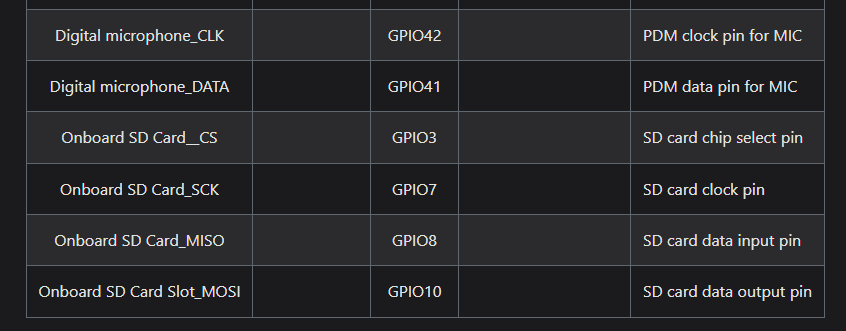
#define SD_CS_PIN 21
TFT_eSPI tft = TFT_eSPI();
void initDisplay() {
Serial.println("initDisplay(): start");
pinMode(TFT_CS, OUTPUT);
digitalWrite(TFT_CS, HIGH); // deselect TFT
pinMode(TFT_DC, OUTPUT);
pinMode(TFT_RST, OUTPUT);
delay(10);
tft.init();
tft.setRotation(1);
tft.fillScreen(TFT_BLACK);
tft.setTextColor(TFT_WHITE, TFT_BLACK);
tft.setTextSize(2);
tft.setCursor(40, 50);
tft.println("Display OK");
digitalWrite(TFT_CS, HIGH); // keep TFT deselected
Serial.println("initDisplay(): done");
}
bool initSD() {
Serial.println("initSD(): start");
pinMode(SD_CS_PIN, OUTPUT);
digitalWrite(SD_CS_PIN, HIGH); // deselect SD first
digitalWrite(TFT_CS, HIGH); // make sure TFT stays off the bus
delay(10);
// Conservative SD startup speed
bool ok = SD.begin(SD_CS_PIN, SPI, 4000000);
if (!ok) {
Serial.println("initSD(): SD.begin failed");
return false;
}
uint64_t cardSize = SD.cardSize() / (1024 * 1024);
Serial.printf("SD mounted. Size: %llu MB\n", cardSize);
if (!SD.exists("/photos")) {
if (SD.mkdir("/photos")) {
Serial.println("/photos created");
} else {
Serial.println("Failed to create /photos");
}
}
Serial.println("initSD(): done");
return true;
}
void setup() {
Serial.begin(115200);
delay(1000);
Serial.println("\n=== XIAO ESP32S3 Sense TFT + SD SPI test ===");
// Shared SPI bus for TFT + Sense SD
SPI.begin(7, 8, 9, -1);
Serial.println("SPI.begin done");
// Put both CS lines in safe state before any library init
pinMode(TFT_CS, OUTPUT);
digitalWrite(TFT_CS, HIGH);
pinMode(SD_CS_PIN, OUTPUT);
digitalWrite(SD_CS_PIN, HIGH);
delay(20);
initDisplay();
// Re-deselect TFT before touching SD
digitalWrite(TFT_CS, HIGH);
delay(20);
bool sdOK = initSD();
tft.fillRect(0, 90, 240, 40, TFT_BLACK);
tft.setCursor(20, 100);
if (sdOK) {
tft.setTextColor(TFT_GREEN, TFT_BLACK);
tft.println("SD OK");
} else {
tft.setTextColor(TFT_RED, TFT_BLACK);
tft.println("SD FAIL");
}
}
void loop() {
}
If this still hangs exactly at SD.begin(), then I would stop trying to “fix code” the likely root cause is Seeed’s own hardware routing rule: the Sense microSD slot is tied to the SPI pins through J3, and Seeed says you cannot use the microSD function and the XIAO SPI function at the same time unless you reconfigure J3.

HTH
GL  PJ
PJ